
 Submit a Paper
 Propose a Special lssue
 Open Access
ARTICLE
Adaptive Nonlinear Sliding Mode Control for DC Power Distribution in Commercial Buildings
1 Thiagarajar Polytechnic College, Salem, Tamilnadu, India
2 Sona College of Technology, Salem, Tamilnadu, India
* Corresponding Author: R. Muthamil Arasi. Email:
Intelligent Automation & Soft Computing 2023, 36(1), 997-1012. https://doi.org/10.32604/iasc.2023.032645
Received 24 May 2022; Accepted 29 June 2022; Issue published 29 September 2022
 View Full Text
 Download PDF
Abstract
The developing populace and industrialization power demand prompted the requirement for power generation from elective sources. The desire for this pursuit is solid due to the ever-present common assets of petroleum derivatives and their predominant ecological issues. It is generally acknowledged that sustainable power sources are one of the best answers for the energy emergency. Among these, Photovoltaic (PV) sources have many benefits to bestow a very promising future. If integrated into the existing power distribution infrastructure, the solar source will be more successful, requiring efficient Direct Current (DC)-Alternating Current (AC) conversion. This paper mainly aims to improve controllers’ performance between AC/DC Energy sources and the DC loads using the Adaptive Nonlinear Sliding Mode (ANSM) control method. The proposed ANSM method efficiently controls power quality issues, such as transient response, power flow reliability and Total Harmonics Distortion (THD). The proposed controller is applied for both AC/DC and DC/DC converters and the performance of the proposed controller is validated through simulation checking the above parameters. The simulation results confirm ANSM configuration is more reliable and efficient than the existing fuzzy and sliding mode control methods.Keywords
Integrating Renewable Energy Source (RES) with existing power systems are proposed to have better performance and efficiency in handling multiple energy sources with ease of feasible implementation and conservation. Solar panels and wind turbines are examples of renewable energy systems. The concept of using Direct Current (DC) in a building power distribution system arose from the need to take advantage of benefits such as rapid development of Photovoltaic (PV) system installation. R. Mohd et al. 2019 [1], the growing use of batteries in commercial buildings. Rosales-Asensio et al. 2019 [2] and the growing nature of DC loads in the market, such as consumer electronics, gadgets, motor drives, and solid-state lighting systems using Light Emitting Diodes (LEDs). Sundareswaran et al. 2019 [3]. Because the DC power distribution system in Buildings. Lai et al. 2019 [4] avoids converting solar DC electricity to AC and then back to DC to provide DC loads, energy transfer losses are greatly reduced.
In today’s environment, commercial buildings utilize 61 percent of the country’s electrical energy Vishwanath et al. 2019 [5], with lighting systems the most common demand. The current power system in business buildings, on the other hand, relies on AC and DC energy from sustainable power sources, which must be converted from DC to AC, then AC to DC to power the DC loads [6,7]. The power transfer efficiency is substantially enhanced when DC power is delivered directly to DC loads through DC Bus. Therefore developing DC distribution systems to adapt to sustainable renewable power sources and DC loads is necessary Kitson et al. 2019 [8]. Tab. 1 depicts the many types of DC loads found in commercial buildings.
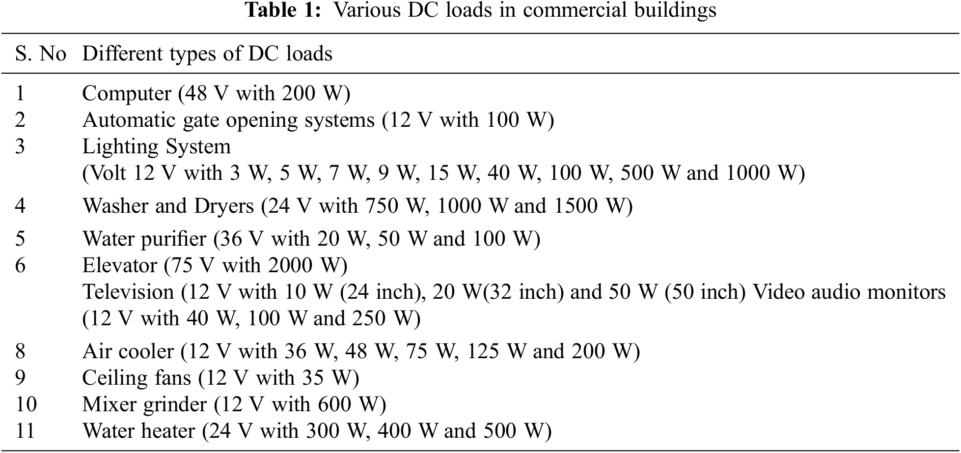
Fig. 1 shows a model of a 48 V DC solar hybrid distribution system for Indian rural banks. This paper offers a DC distribution system for commercial buildings that includes both AC and DC sources. Pulse Width Modulation (PWM) current and voltage mode control, Proportional Integrated (PI), and Proportional Integrated Derivative (PID) control [9–15] are the most used control techniques for AC to DC and DC to DC converters. Under fluctuating loads and power system conditions, these traditional control techniques do not function well. Under heavy load and power system fluctuation circumstances, the current Nonlinear Sliding Mode Method Rehman, Abdul Ashraf et al. 2018 [16–19] performs adequately, but it does not account for transitory conditions. Therefore, in this work, an Adaptive Nonlinear Sliding Mode method is introduced to accommodate transient and steady-state conditions and performance parameters like peak time, peak overshoot time, recovery time, steady-state error, and THD verified.
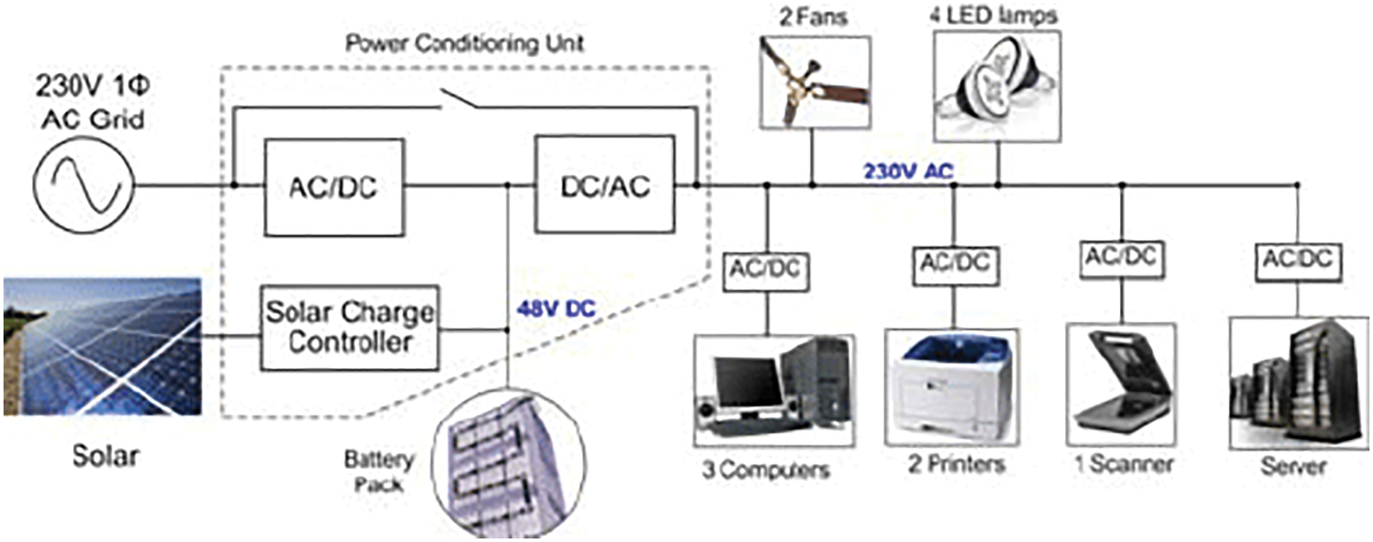
Figure 1: 48 V DC solar hybrid distribution system for Indian rural banks
2 Proposed Converter Design and Analysis
The functional working diagram of the proposed system is shown in Fig. 2. In this work, Adaptive Nonlinear Sliding Mode (ANSM) Controller is used to control the switching operation of the converters. The power converters connected to the sources and the common DC bus will be controlled under an ANSM. The proposed ANSM control technique generates continuous 380 V DC. Hernández et al. 2018 [20] based on the PV panel and AC supply reference signals. The numerical simulation of this model ensures the accurate operation of the supervisory controller and its algorithm functions in different operating conditions [21–23].
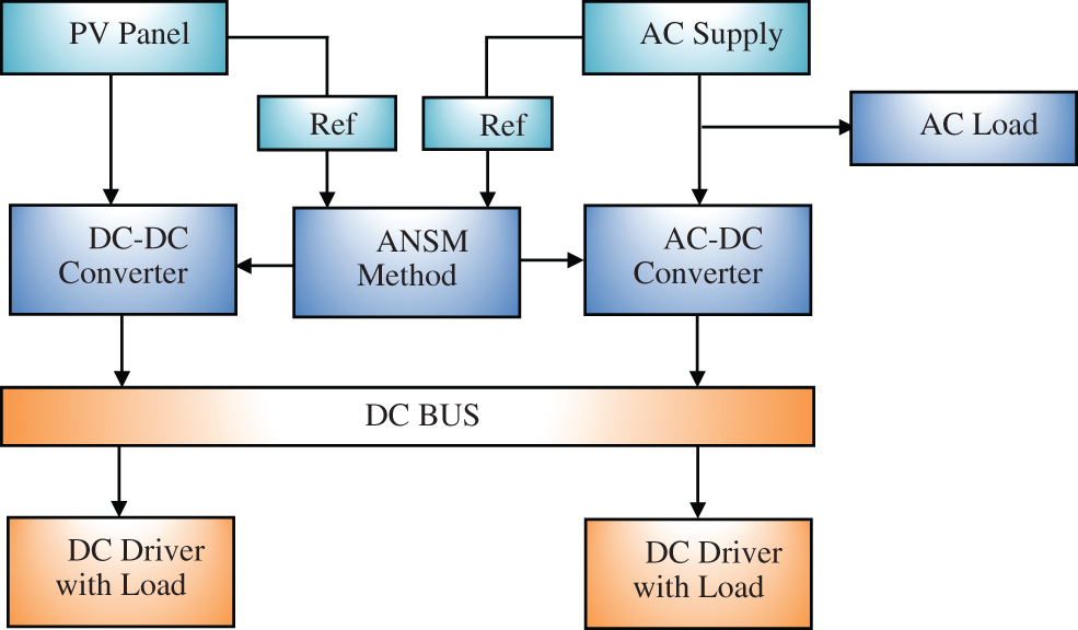
Figure 2: Block diagram of proposed system
2.1 Operation of DC-DC Boost Converter Circuit
Fig. 3 depicts the DC-DC boost converter’s circuit diagram. This paper proposes a simpler analysis of a new modulation method for converting boost converters called the ANSM Modulation Scheme. It features two different width trains to mitigate high pulse distortions and reduce power loss in power electronic systems. Single switched PWM DC-DC Boost Converters were employed in the suggested modulation method.
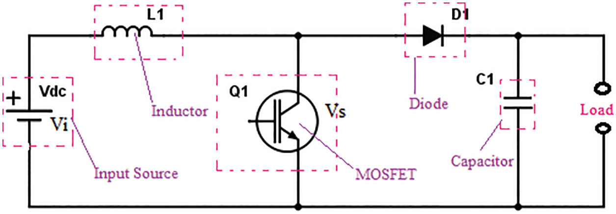
Figure 3: Circuit diagram of boost converter
The modulation technique created by this type minimizes high-order synchronization while the narrow region of the wide lentil segment reduces low-order synchronization. Zero number counts the signal and is in ascending and descending stairs. The ascending region is the inverse of the descending region. The amplitude of the voltage signal is equal to the height of the modulating signal.
2.1.1 Modes of Operation for Proposed DC-DC Converter
The function of the DC-DC converter is to be controlled and kept constant under steady-state against variations in input voltage and load. The proposed SMC function is designed to adjust the time-varying proportional area of the step/pulse according to the control of the Adaptive Nonlinear sliding mode.
where,
Rs = Sliding space; D∞ = Reference Output Voltage; Ao = Obtained output voltage; X1 = Positive Switching interval
If
where: Qs = trending path
Then the corresponding trending law is defined by
Based on the output track system, the transformation function of the nonlinear sliding mode is computed. When the difference between the reference and actual output voltages is zero, Eq. (6) becomes:
The values of the load barrier can be seen well in itself when determining the independent and sliding coefficients of the controller inductor. Accordingly, the converter operates in two different modes-Continuous Current Mode (CCM’s) and Discontinuous Current Mode (DCM).
As shown in Fig. 4, when the duty cycle is such that the inductor current flow is continuous during the entire switching period in both charging as well as discharging timings and the current does not reach zero, it is CCM operation In Fig. 4, D1TS and D2TS are the transition cycles, D1 is the ratio of duty cycle and D2 y = 1-D.
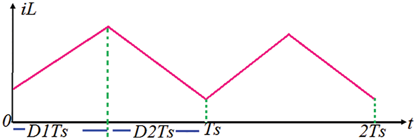
Figure 4: Inductor current response-CCM operation
As shown in Fig. 5, when the duty cycle is such that the inductor current flow is continuous during the entire switching period in both charging as well as discharging timings and the current does cross zero to swing between positive and negative, it is Forced CCM (FCCM) operation
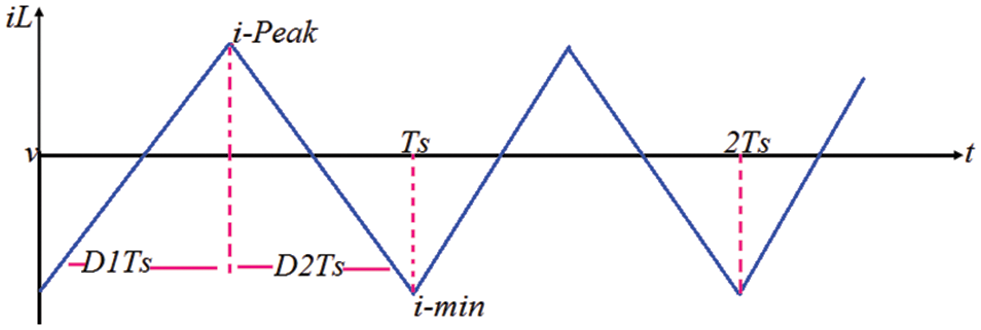
Figure 5: Inductor current-FCCM
The operation of the boost converter CCM, the signal, output voltage fluctuation, diode current, and power inductor current are illustrated in Fig. 6.
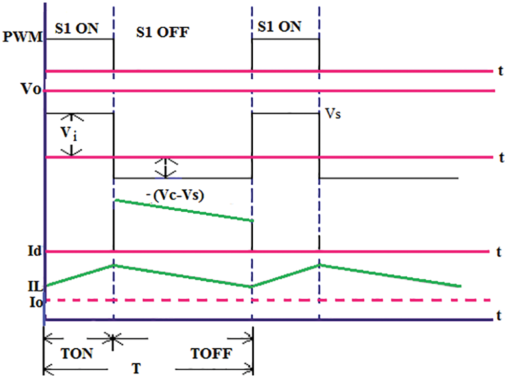
Figure 6: VI Characteristics with time in CCM
2.1.3 Discontinuous Current Mode
If the duty cycle value is selected, the discharging is completed before the end of one time period Ts. The inductor current will reach zero for a small period D3Ts, as shown in Fig. 7.
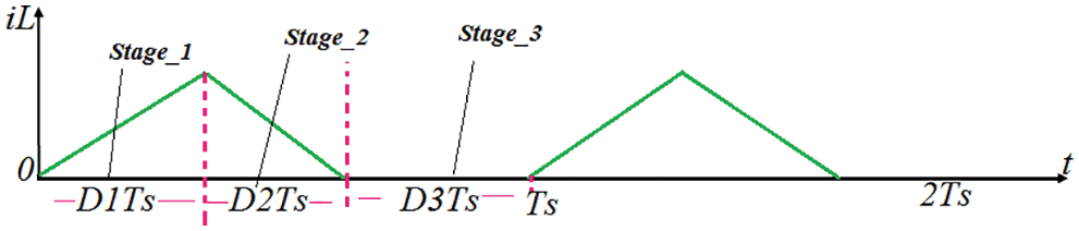
Figure 7: Inductor current response-DCM operation
The operation of DCM is consists of three stages. Here D1 is the duty cycle, D2 = (1-(D1-D3) and D3 = (1-(D1-D2). During the third interval-D3TS, the current is Zero. The DCM standardized output voltage has no linear relationship with the input voltage as of the CCM. The signal, output voltage variation, diode current and current inductor current in the DCM function of the boost converter is depicted in Fig. 8.
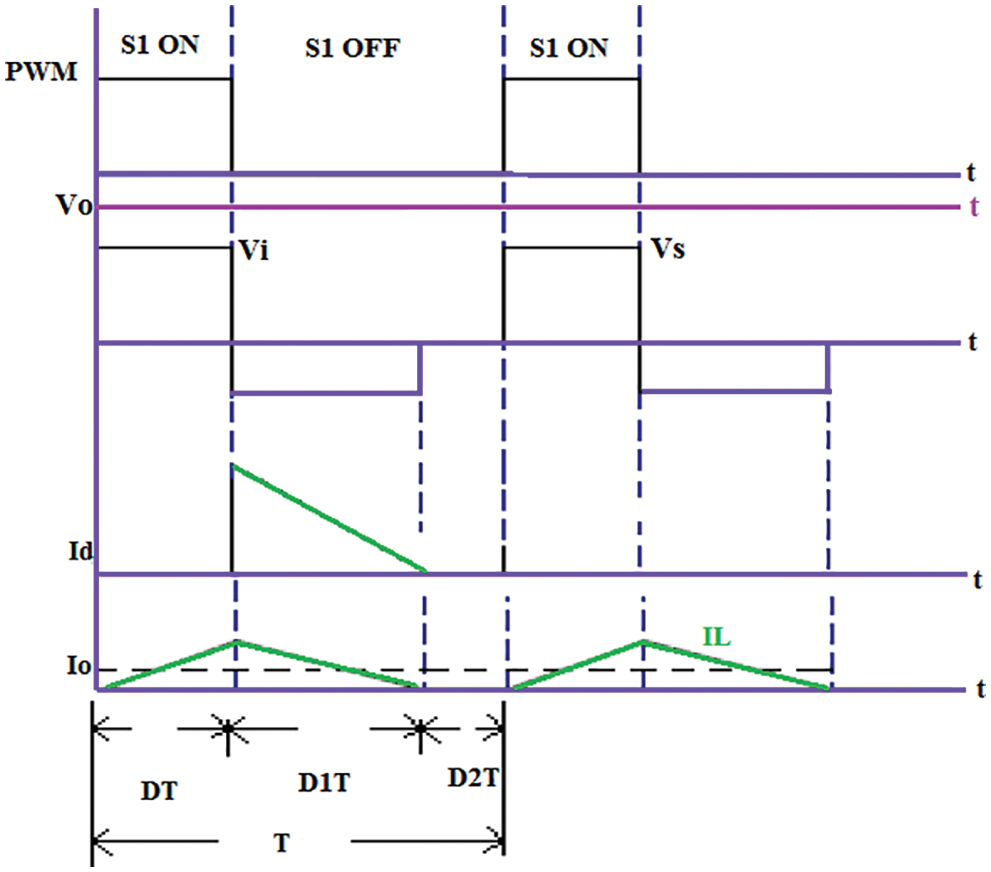
Figure 8: IV characteristics with time in DCM
2.2 Operation of AC-DC Converter
This area depicts the activity of the proposed single-stage AC to DC converter. Fig. 9 shows the proposed block chart for AC-DC converter with an Adaptive Nonlinear sliding Mode Control strategy. The ANSM control strategy gives the ideal outcomes against different boundaries, such as voltage adjustment, unity power factor, and decreasing switching losses.
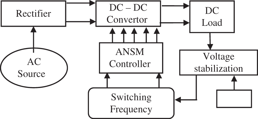
Figure 9: AC-DC Converter-block diagram
2.2.1 Buck-Boost Converter Circuit
The proposed ANSM-based buck-boost converter is shown in Fig. 10, suitable for both step-up and step-down applications. This work obtains step up and step-down output voltage characteristics through a suitable transition scheme by switching power semiconductor switch.
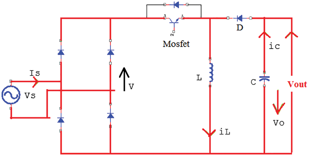
Figure 10: Circuit diagram of buck-boost converter
The Buck-Boost Converter operates in three operating modes and each having sub-modes. Charging mode (mode 1)
The switching device MOSFET is in charging mode, diode D is in reverse bias, and supply voltage appears across the inductor. As illustrated in Fig. 11, the inductor current should climb towards IL and follow a return path to the AC input side. The charge stored in the capacitor C in the previous Period also drives the inductor through the diode. Green lines in Fig. 11 indicate current paths in the circuits in this mode.
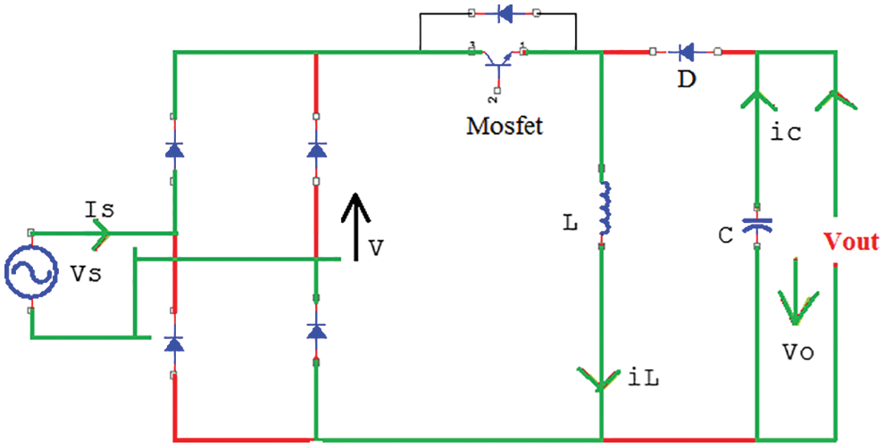
Figure 11: Mode-1 MOSFET-ON and diode DOFF
Discharging mode (mode 2)
The circuit diagram of Mode 2 is shown in Fig. 12. In this mode, the swathing device MOSFET is there in OFF state, Diode D is forward bias, and the output voltage IL drops across inductor IL. Attempting to leave its post passing through a head diode D in anticipation of the voltage load of the inductor changes its peak and burns and charges the capacitor as the requirements remain.
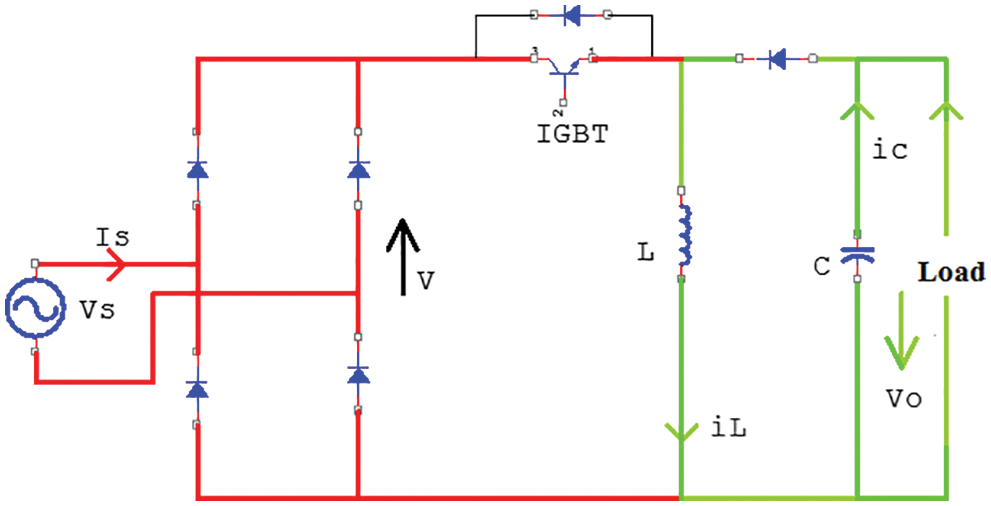
Figure 12: Mode-2 MOSFET-OFF and diode D-ON
Mode 3 (Off Mode)
The circuit diagram of mode3 is shown in Fig. 13. The switching device MOSFET is in the OFF state in this mode. The inductor current IL falls to zero, and the reversing bias diode (D) is activated. The operation of this model continued until the MOSFET turned ON.
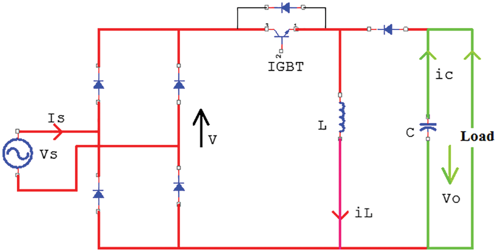
Figure 13: Mode-3 MOSFET is OFF, and diode DOFF
2.2.3 Inductor Current and Voltage Response During One Switching Cycle
Fig. 14 depicts the voltage and current responses in both CCM and DCM during a single switching cycle.
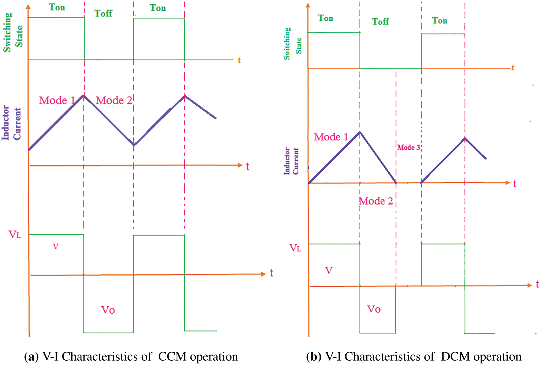
Figure 14: VI characteristics of voltage and current response
2.3 Optimization and Power Management Analysis of Converters Using Adaptive Nonlinear Sliding Mode Control Strategy
Power management is the main requirement of a power converter system. The strategy of the circuit to handle both source-side imbalances and load-side variations is adaptively optimized in the controller and executed to stabilize the overall system performance. This work proposes optimal control in an adaptive nonlinear sliding control approach involving individual parameter control arising due to nonlinearities. The new results depend on the traditional hypothesis of ideal control that permits the ongoing outcomes to unravel the framework issues. All the more explicitly, ANSM is utilized to discover arrangements that are good for compelling force the board with the unimportant loss of intensity.
ANSM-Algorithm Steps
Step1: Size of the populace (s) and repetitions (j) are initialized.
Step2: Select samples from general population, where j = 1, 2, 3….for different loads. Set the boundaries for the maximum number of repetitions.
Step3: Specify the ideal limit with the ultimate objective that assesses different loads with voltage modifications.
Step4: Compute the boundaries by considering the three facts (i) different load conditions ii) Input power factor. iii) Switching frequency and duty cycle of converters.
Step 5: Calculate the testing periods Ti + 1 based on the quality requirement
Step6: Based on the response of testing results, the error value is computed
Step 7: From the error value, the load’s error rate is adjusted
Step8: If the state of the movement of the issue isn’t fulfilled, go to step3.
Step9: Upgrade the new adjustments of the individual loads in the general population freely.
Step10: If the error value is high, go to step3 and repeat the process
Step11: If the end outcome is met, fix the possible ideal plan in the request space.
The algorithm is developed for the ANSM control of the proposed DC-DC and AC-DC converters to manage the PWM signals of the switching devices of the converters. The following parameters are utilized to assess the performance of (i) Transient response in terms of Peak time, Peak overshoot and steady-state error, (ii) Total Harmonic Distortion (THD) and (iii) Overall System Efficiency.
3 Simulation Results and Discussion
The Proposed solar-based DC distribution system is implemented in the Simulink model and simulated in the MATLAB software. Two primary blocks make up the proposed simulation system: AC-DC converter and DC-DC converter. The DC load has a capacity of 2000 W and operates at 12, 24, and 48 V. Here we’ll talk about the simulation circuit and the findings we got.
3.1 Performance Analysis of Solar DC-DC Converter
Below are the simulation results and performance analysis of a DC-DC converter with a solar source. The suggested solar-based DC-DC converter’s Simulink model is illustrated in Fig. 15, and the simulation parameters are provided in Tab. 1. In this work, the ANSM strategy generates the PWM and maintains the constant DC voltage.
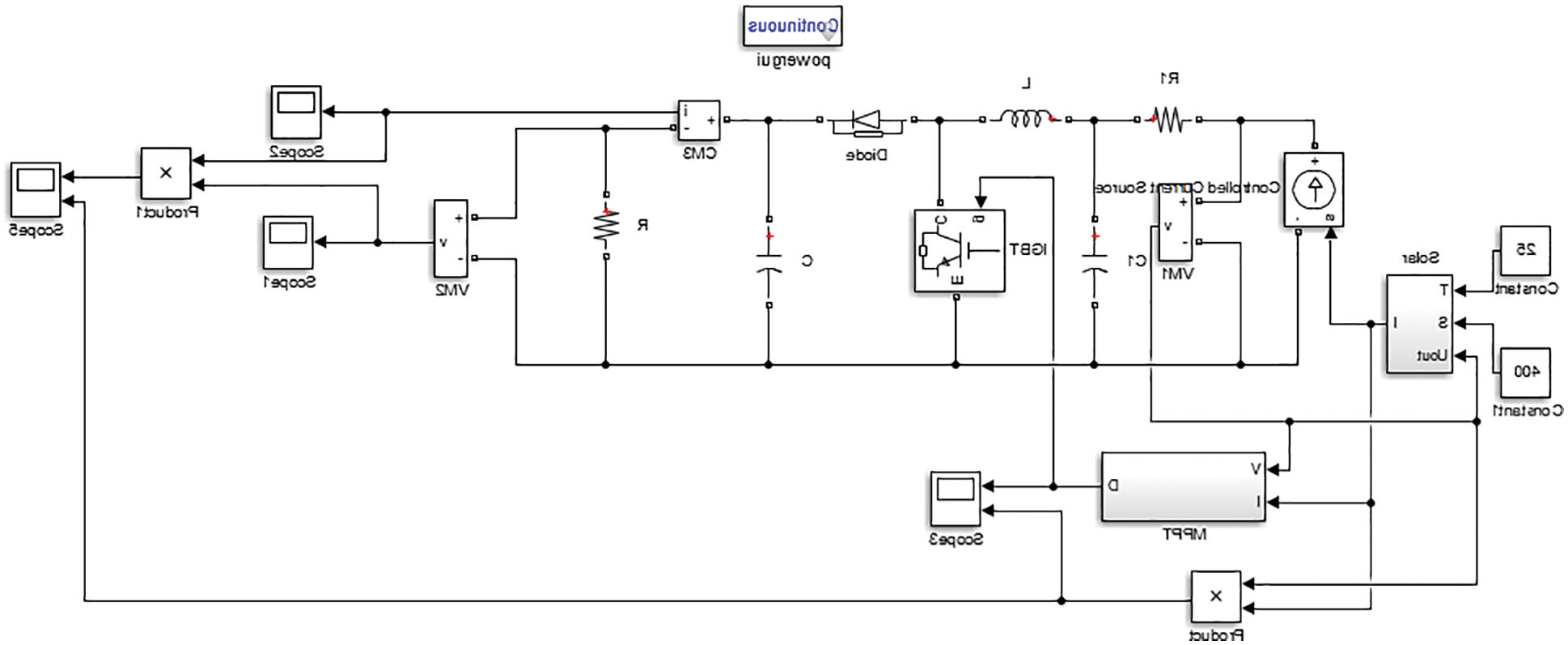
Figure 15: Simulink model solar with DC-DC converter
Fig. 16 shows the DC-DC Converter’s input voltage from a solar source, with a DC input voltage of 200 V. The Voltage and current response of the switching device MOSFET is shown in Figs. 16b and 16c. respectively. The DC-DC Converter voltage response across the DC bus from the DC-DC converter is shown in Fig. 16d. The load voltage response and current response of the proposed system for a 48 V Permanent Magnet DC (PMDC) motor is shown in Figs. 16e and 16f.
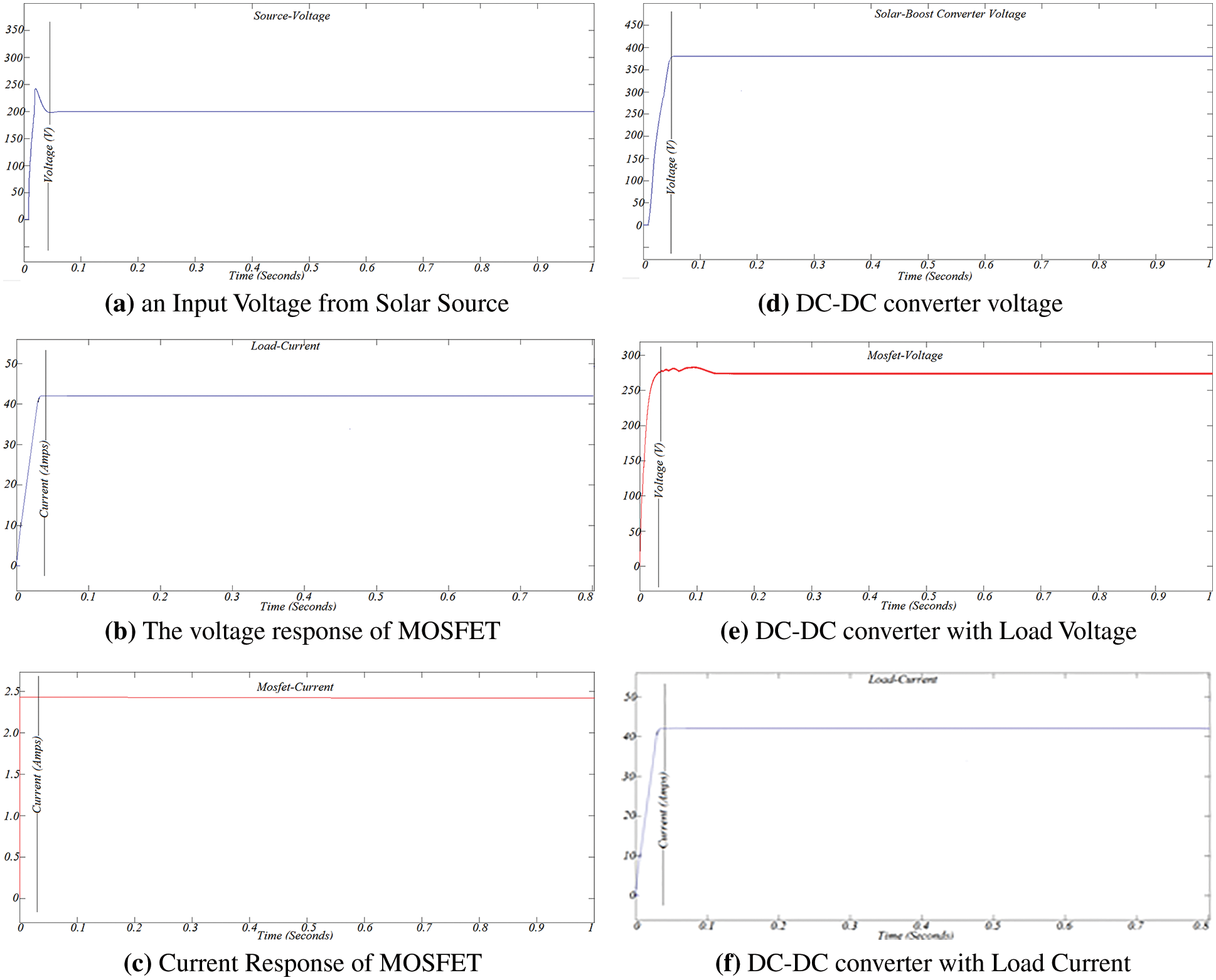
Figure 16: (a) An Input voltage from solar source (b). The voltage response of MOSFET (c) Current response of MOSFET (d). DC-DC converter voltage (e) DC-DC Converter with load voltage (f). DC-DC converter with load current
3.2 Performance Analysis of AC-DC Converter
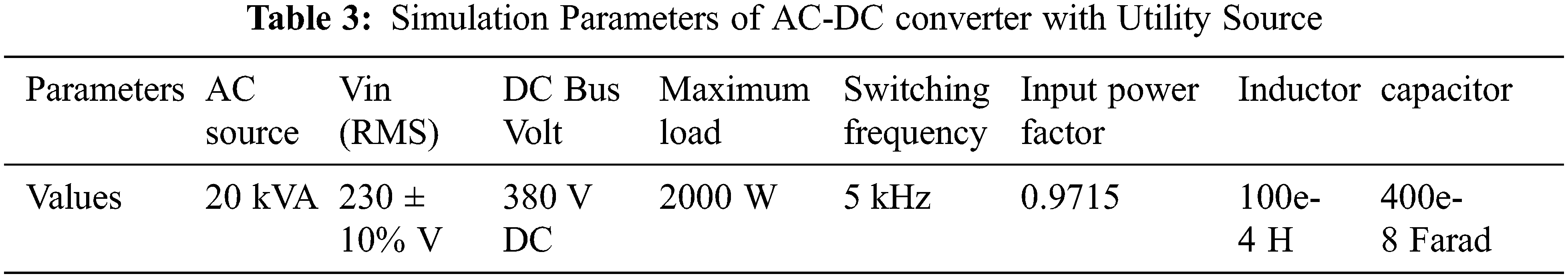
This section discusses the simulation results and performance analyses of the AC-DC converter. The suggested solar-based AC-DC converter’s Simulink model is illustrated in Fig. 17, and the simulation parameters are provided in the Tabs. 2 and 3. The ANSM method is utilized to produce the PWM and keep the DC voltage constant in this study.
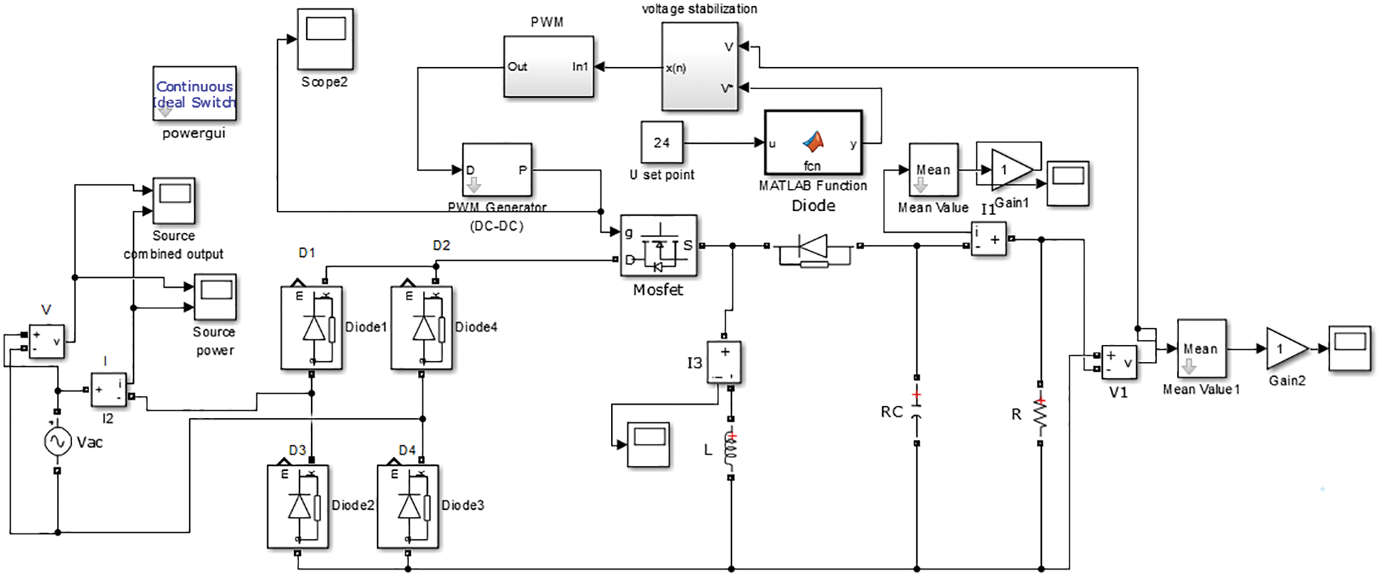
Figure 17: Simulink model of proposed AC-DC converter

The input voltage and current of the AC-DC Converter are shown in Fig. 18a with an AC input voltage of 230 V. The Voltage and current response of the switching device MOSFET is shown in Figs. 18b and 18c. respectively. The inductor current response is shown in Fig. 18d. The AC-DC Converter voltage across the DC bus from the is shown in Fig. 18e. The proposed system’s load voltage response and current response for a 48 V PMDC motor are shown in Figs. 18f and 18g.
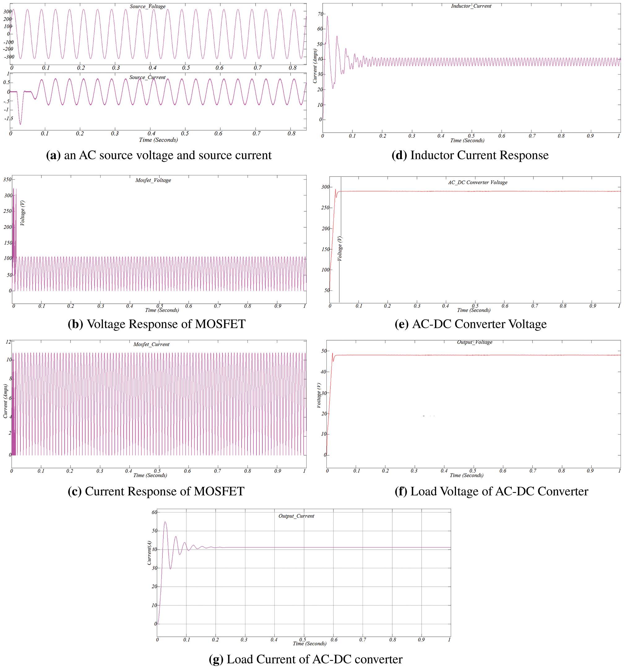
Figure 18: (a) An AC source voltage and source current (b) Voltage response of MOSFET (c) Current response of MOSFET (d) Inductor current response (e) AC-DC Converter voltage (f) Load voltage of AC-DC converter (g) Load current of AC-DC converter
3.3 Analysis of Total Harmonic Distortion
The THD analysis of the proposed converter is shown in Fig. 19. The proposed ANSM obtain the THD value of 3.31% only.
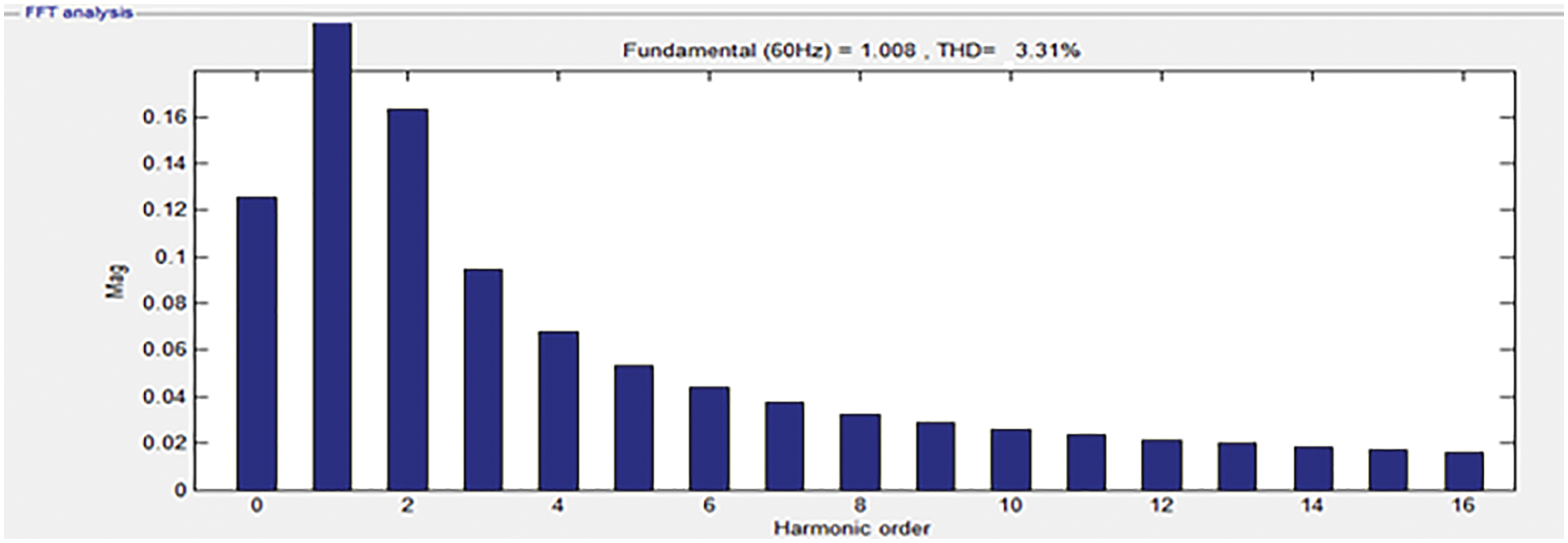
Figure 19: THD analysis for proposed system
The performance analysis of control system parameters is discussed in Tab. 4 and Fig. 20. This comparison confirms that the proposed ANSM method achieves the best results, as compared with conventional methods.
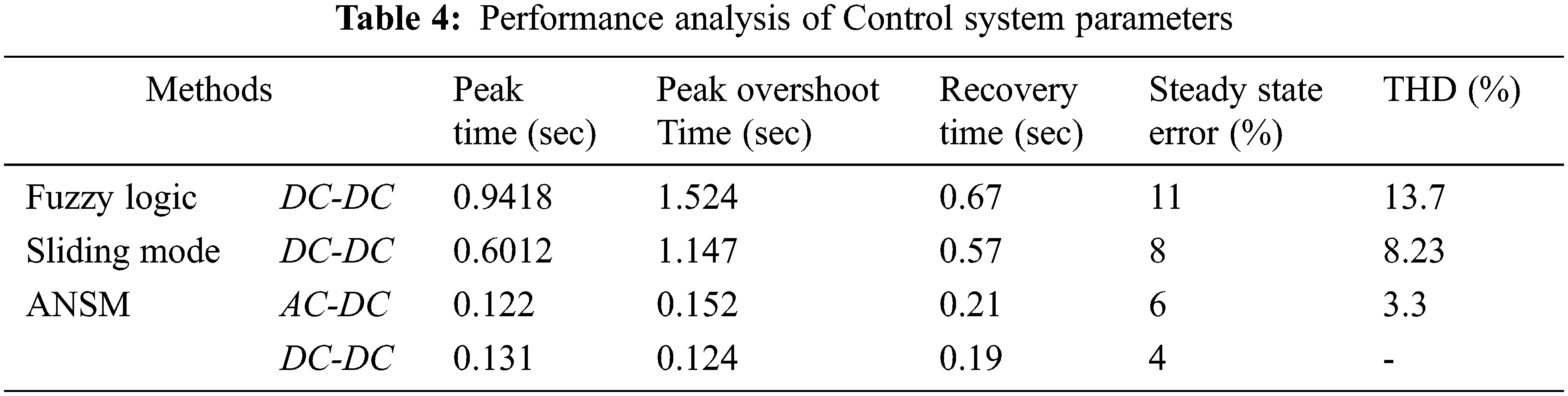
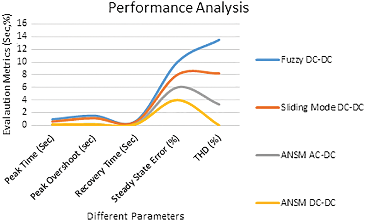
Figure 20: Performance analysis
This work proposes an Adaptive Nonlinear Sliding Mode method of control that can drive the DC loads in commercial buildings from both AC and DC sources. The objective is to maintain constant DC bus voltage considering different operating conditions. The proposed system avails maximum utilization of PV sources. The DC bus voltage levels are monitored to coordinate the system’s sources and storage and regulate the switching device under various operating situations. The suggested control techniques for integrating PV sources, utility sources, and energy storage in commercial buildings will be validated using system simulations. Compared with the existing system, the proposed method achieves the best results. For example, peak time is 012, peak overshoot time is 015 sec, recover time is 0.20 sec, the steady-state error is 6% and THD is 3.31%.In the Future, introduce deep learning methods to improve the power quality issues for solar-based commercial building application systems. The simulation results show that the suggested source design is more dependable and efficient than the current source configuration. Compared with the existing system, the proposed system achieves better results. For example, peak time is 0.12 sec, peak overshoot time is 0.15 sec, recovery time is 0.20 sec, the steady-state error is 6% and THD is 3.31%. Future neural networks with optimization methods will be involved to improve the power quality issues of the DC Distribution in commercial buildings.
Funding Statement: The authors received no specific funding for this study.
Conflicts of Interest: The authors declare that they have no conflicts of interest to report regarding the present study.
References
1. R. Mohd, M. Sharip, M. Ahmed. A. Haidar and C. Aaron Jimel, “Optimum configuration of solar PV topologies for DC micro grid,” International Journal of Photo Energy, vol. 4, no. 23, pp. 13–26, 2019. [Google Scholar]
2. R. Asensio, E. Simón-Martín, M. Borge-Diez, D. Blanes Peiró, J. Juan et al., “Micro grids with energy storage systems as a means to increase power resilience: An application to office buildings,” Energy & Elsevier, vol. 172, no. 4, pp. 1005–1015, 2019. [Google Scholar]
3. K. Sundareswaran, K. Ark Kumar, K. Raman Venkateswaran and P. P. Sathya, “Solar photovoltaic fed dual input LED lighting system with constant illumination control,” Frontiers in Energy, vol. 14, no. 26, pp. 213–231, 2016. [Google Scholar]
4. K. Lai, E. Muir, S. Erboy Ruff and Z. Yasemin, “Off-grid appliance performance testing: Results and trends for early-stage market development,” Energy Efficiency, vol. 13, no. 2, pp. 232–244, 2019. [Google Scholar]
5. S. Vishwanath, A. Chandan, V. Saurav and L. Kumar, “An IoT based data driven pre-cooling solution for electricity cost savings in commercial buildings,” IEEE Internet of Things Journal, vol. 12, no. 23, pp. 1–1, 2019. [Google Scholar]
6. G. Arunkumar Devaraj, P. Elangovan, P. Sanjeevi kumar, H. Nielsen and L. Peter, “DC grid for domestic electrification,” Energies, vol. 24, no. 9, pp. 236249, 2019. [Google Scholar]
7. E. Gelani, H. Dastgeer, F. Siraj, K. Nasir, M. Niazi et al., “Efficiency comparison of AC and DC distribution networks for modern residential localities,” Applied Sciences, vol. 9, no. 4, pp. 213–226, 2019. [Google Scholar]
8. J. Kitson, S. J. Williamson, P. W. Harper Mcmahon, C. G. Rosenberg, M. Tierney et al., “Modelling of an expandable, reconfigurable, renewable DC micro grid for off-grid communities,” Energy, vol. 06, no. 219, pp. 415–429, 2018. [Google Scholar]
9. S. Comello, L. Reichelstein and S. Sahoo, “The road ahead for solar PV power-renewable and sustainable,” Energy Reviews, vol. 92, no. 8, pp. 744–756, 2018. [Google Scholar]
10. S. Chuang, K. Hsing-Lung Den, W. Iskandar, L. Liao and P. Hsuan. “The relationship between electricity emission factor and renewable energy certificate: The free rider and outsider effect,” Sustainable Environment Research, vol. 28, no. 18, pp. 513–531, 2018. [Google Scholar]
11. Y. Zhou and X. Chen, “Mechanism of CO2 emission reduction by global energy,” Interconnection Global Energy Interconnection, vol. 1, no. 4, pp. 409–419. 2018. [Google Scholar]
12. X. Zandi and Z. Mazinan, “Maximum power point tracking of the solar power plants in shadow mode through artificial neural network,” Complex & Intelligent Systems, vol. 19, no. 13, pp. 13–29, 2019. [Google Scholar]
13. K. Mossad, I. Mohamed, O. abed el-Raouf, M. Alahmar and Z. Fahd, “Maximum power point tracking of PV system based cuckoo search algorithm; review and comparison,” Energy Procedia, vol. 4, no. 13, pp. 117–126. 2019. [Google Scholar]
14. K. Schuss, V. Christian and L. Fabritius, “Moving photovoltaic installations: Impacts of the sampling rate on maximum power point tracking algorithms,” IEEE Transactions on Instrumentation and Measurement, vol. 12, no, 5, pp. 1–9, 2019. [Google Scholar]
15. N. Krishnaraj, M. Elhoseny, E. Laxmi Lydia, K. Shankar and O. ALDabbas, “An efficient radix trie-based semantic visual indexing model for large-scale image retrieval in cloud environment,” Software: Practice and Experience, vol. 51, no. 3, pp. 489–502, 2021. [Google Scholar]
16. L. Anzalchi and A. Sarwat, “Overview of technical specifications for grid-connected photovoltaic systems,” Energy Convers, vol. 12, no. 15, pp. 2312–327, 2017. [Google Scholar]
17. J. H. Jo, M. Aldeman and R. D. G. Loomis, “Optimum penetration of regional utility-scale renewable energy systems,” Renewable Energy, vol. 2, no. 118, pp. 328–334, 2018. [Google Scholar]
18. C. Vezzoli, “Distributed/decentralized renewable energy systems. in: Designing sustainable energy for all green energy and technology,” Springer, vol. 15, no. 4, pp. 12–31, 2018. [Google Scholar]
19. S. Cheng, K. Lefeng Zhang, L. Zhiyi Jiang, H. Tao, Y. Wang et al., “Local energy management and optimization: A novel energy universal service bus system based on energy internet technologies,” Energies, vol. 4, no. 15, pp. 322–341, 2018. [Google Scholar]
20. J. L. Hernandez, R. Sanz, A. Corredera, R. Palomar and I. Lacave, “A Fuzzy-based building energy management system for energy efficiency,” Buildings, vol. 8, no. 2, pp. 326–339, 2018. [Google Scholar]
21. K. Rehman, A. Ashraf, M. Bhatti and Z. Aamer, “Fixed frequency sliding mode control of power converters for improved dynamic response in DC micro-grids,” Energies, vol. 11, no. 16, pp. 31–45, 2018. [Google Scholar]
22. N. Krishnaraj, B. Sivakumar, R. Kuppusamy, Y. Teekaraman and A. R. Thelkar, “Design of automated deep learning based fusion model for copy-move image forgery detection,” Computational Intelligence and Neuroscience, vol. 2022, no. 8501738, pp. 1–13, 2022. [Google Scholar]
23. R. Saravanakumar, N. Krishnaraj, S. Venkatraman, B. Sivakumar, S. Prasanna et al., “Hierarchical symbolic analysis and particle swarm optimization based fault diagnosis model for rotating machineries with deep neural networks,” Measurement, vol. 171, no. 108771, pp. 1–12, 2021. [Google Scholar]
Cite This Article
 Copyright © 2023 The Author(s). Published by Tech Science Press.
This work is licensed under a Creative Commons Attribution 4.0 International License , which permits unrestricted use, distribution, and reproduction in any medium, provided the original work is properly cited.
 Downloads
 Citation Tools