
 Submit a Paper
 Propose a Special lssue
 Open Access
ARTICLE
Effect of Inclined Tension Crack on Rock Slope Stability by SSR Technique
Visvesvaraya National Institute of Technology, Nagpur, 440010, India
* Corresponding Author: Ch. Venkat Ramana. Email:
Intelligent Automation & Soft Computing 2023, 36(1), 1205-1214. https://doi.org/10.32604/iasc.2023.031838
Received 28 April 2022; Accepted 08 July 2022; Issue published 29 September 2022
 View Full Text
 Download PDF
Abstract
The tension cracks and joints in rock or soil slopes affect their failure stability. Prediction of rock or soil slope failure is one of the most challenging tasks in the earth sciences. The actual slopes consist of inhomogeneous materials, complex morphology, and erratic joints. Most studies concerning the failure of rock slopes primarily focused on determining Factor of Safety (FoS) and Critical Slip Surface (CSS). In this article, the effect of inclined tension crack on a rock slope failure is studied numerically with Shear Strength Reduction Factor (SRF) method. An inclined Tension Crack (TC) influences the magnitude and location of the rock slope’s Critical Shear Strength Reduction Factor (CSRF). Certainly, inclined cracks are more prone to cause the failure of the slope than the vertical TC. Yet, all tension cracks do not lead to failure of the slope mass. The effect of the crest distance of the tension crack is also investigated. The numerical results do not show any significant change in the magnitude of CSRF unless the tip of the TC is very near to the crest of the slope. A TC is also replaced with a joint, and the results differ from the corresponding TC. These results are discussed regarding shear stress and Critical Slip Surface (CSS).Keywords
Prediction of rock or soil slope failure is one of the most challenging tasks in the earth sciences. The actual slopes consist of inhomogeneous materials, complex morphology, and erratic joints [1–5]. [1] The majority of studies concerning the failure of rock slopes are primarily focused on determining Factor of Safety (FoS) and Critical Slip Surface (CSS) [6–9]. The safety factor is often defined as the ratio of failure strength of the slope material to driving stress acting along a predefined CSS of the slope [1,9]. An important issue is determining the location of failure joints or both [10]. It has been established that nucleation and propagation of a crack results in fracture of the slope mass. Tension cracks are quite common in rock and soil slopes, and they often weaken their failure stability [11–15]. In the slope stability analyses with cohesive soils, tension cracks may be observed in the upper part of the slope due to the development of tensile forces. A tension crack essentially terminates the slip surface [16,17]. [9] Tension cracks and joints also affect the stability of pit slopes which are prominent in opencast mines [18–21]. Fig. 1 shows a typical view of tension cracks near the crest of the pit slope at an opencast coal mine in Godavari Valley Coalfield, India. It is also believed these cracks are inclined in the bulk of the pit slope.
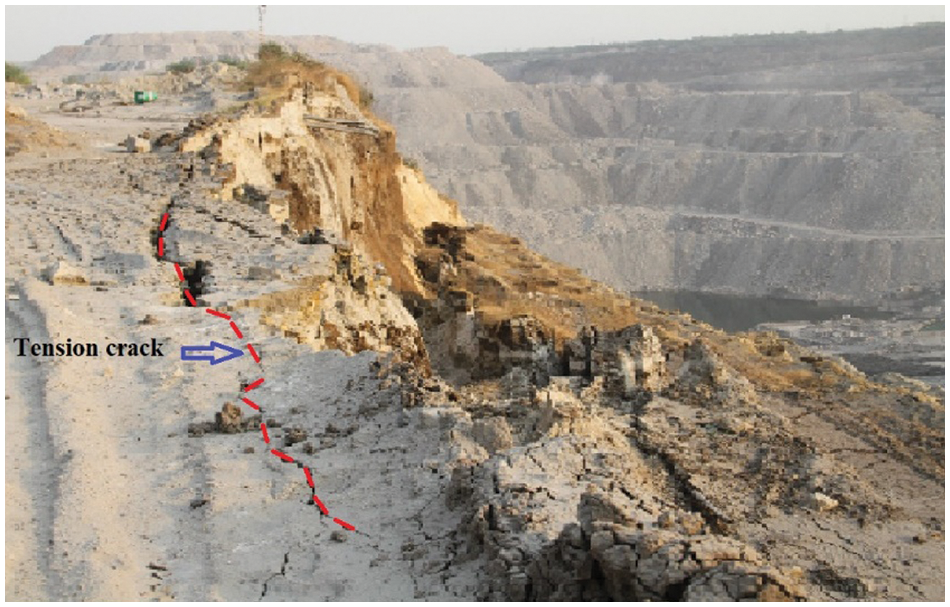
Figure 1: A typical view of tension crack near the pit slope edge of an open cast mine of Godavari valley coalfield, India
Despite extensive theoretical and experimental studies, many issues are not yet clear. For instance, it is not known how the inclination, length of TC, and distance from the crest influence the stability of the slope. The effect of TC on slope stability has been studied using both analytical and numerical approaches [12,15]. Nevertheless, these studies have considered only a vertical TC [1]. While a slanted TC may also appear in the slope mass [15], the effect of such a crack on the stability of the rock slope is known in the literature.
In recent times, a Finite Element Method (FEM) based on Shear Strength Reduction Factor (SRF) is often used in the determination of the magnitude and location of FoS [22–26]. SRF method is quite helpful since it is based on shear strain localization at which displacement becomes non-convergent during the numerical simulations of the slope mass [22,23,25]. More significantly, it automatically chooses CSS along which failure of slope mass occurs [25]. Noting the critical value of SRF, CSRF signifies the local value of FoS [9,24]. Further, the magnitude of CSRF is less than unity, indicating the failure of the slope and location of the same is the point of crack nucleation [27]. It has been observed that further increase of SRF results in global failure of the slope mass along with CSS [27]. Studies have shown that although the magnitude of CSRF changes linearly with cohesion and angle of internal friction of slope rock mass, the location of CSRF does not depend on it [28,29]. In the present study, the effect of an inclined tension crack on CSRF is investigated numerically as a function of inclination angle and crest distance of TC [30,31]. Further, TC is replaced with a joint to examine the effect of a sloping mass on CSRF/FoS.
The computational slope model is prepared precisely referring to the field situation in one of the opencast coal mines of Godavari Valley Coalfields. Fig. 2. shows a typical two-dimensional rock slope model of fixed width and height with slope angle β = 55°. A Tension Crack (TC) of finite length d, and inclination angle α, is created at a distance b from the crest of the rock slope. The material of the rock slope is assumed to be homogenous and isotropic with elastic modulus, and density is 0.15 GPa, and 22.0 kN-m−3, respectively. It is also believed that surfaces of the TC are not interacting at all, and gravitational force is acting uniformly in a downward direction on the rock slope [1]. The hydrostatic stress field (ratio of in-plane & out of plane horizontal to vertical stress = 1) is also considered. The model’s left, right, and bottom boundaries are restrained in both X and Y directions, whereas the slope’s top, bottom, and face are kept unrestrained. The domain of the slope model is discretized with 6-noded Triangular elements (T6) of uniform meshing. The total number of factors and nodes in the slope model are 2591 and 5372, respectively.
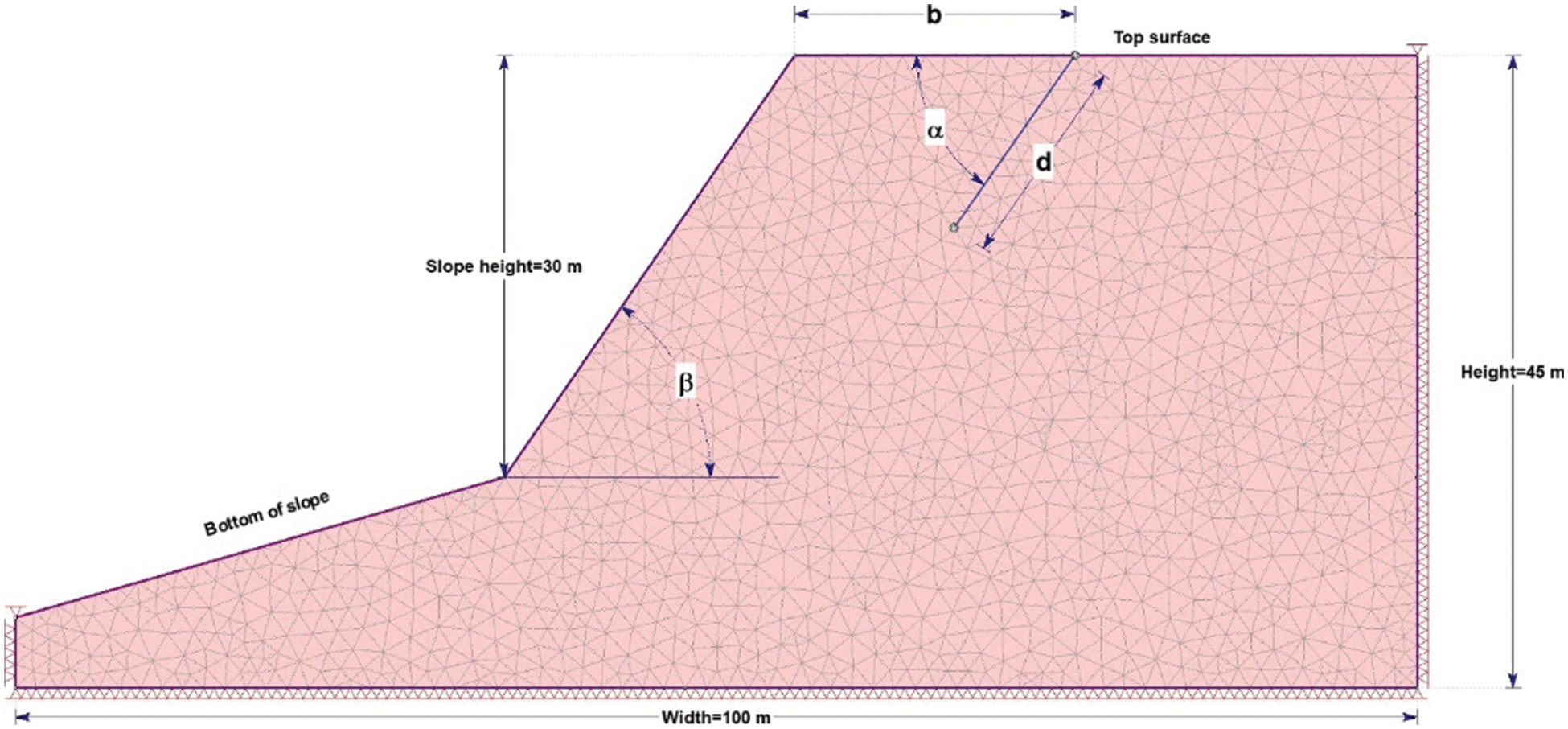
Figure 2: A typical rock slope model developed with assumed fixed width = 100 m, height = 45 m. The height of the slope is 30 m, and the slope angle = 55°. A TC of length and inclination angle which is located at a distance b from the crest of the slope
The Mohr-Coulomb (MC) failure criterion is used in the numerical simulations of the slope mass [1]. According to this criterion, shear strength T depends on cohesion c, normal stress σn, and the angle of internal friction φ as T = c + σn· tanΦ [1]. In the present analysis, cohesion, c = 85.0 kPa, and angle of internal friction, φ = 20° are considered in the numerical simulations of the weathered rock. FEM-based SRF method numerical modelling software, i.e., RS2, is used to determine CSRF and CSS of the bench slopes for varying inclination angle α, crack length d, and crest distance b of TC.
3 Effect of Tension Crack Dip Angle on Critical SRF
The results in Fig. 3a show that the crack’s inclination angle α is insignificant for small crack lengths. For instance, a TC of length d = 6.0 m, located at a crest distance b = 10.0 m, the magnitude of CSRF is 1.25. This is slightly lower than CSRF = 1.26, when there is no TC in the rock slope, as shown in Fig. 4a. It is also seen in Fig. 3a. that at the fixed crack of lengths d = 7.5 & 9.0 m, CSRF increases first with α, after that remains constant with α = (60°, 90° & 120°) and then CSRF decreases as α increases further. An important conclusion from Fig. 3a. is that certainly inclined cracks, for example, α = (30°, 45°, 135°, and 150°), are more to cause instability in the slope than the vertical TC (α = 90°) or the TC with α = 60° and 120°.
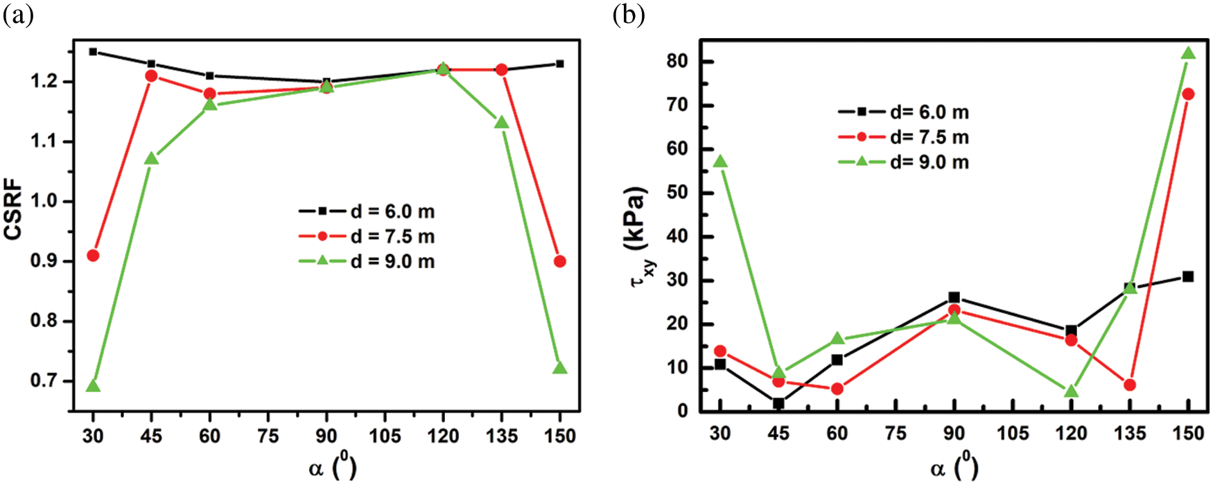
Figure 3: (a) Effect of the inclination angle
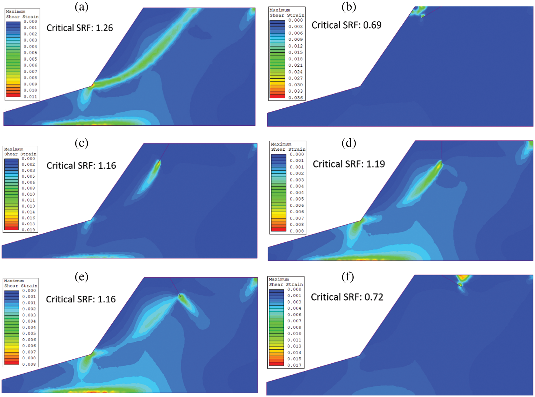
Figure 4: Location of CSRF and CSS (a) no TC (b)
Variation of shear stress τxy at the crack tip is also studied in Fig. 3b. It is observed that it shows the opposite trend compared with CSRF vs. α in Fig. 3a. For instance, it decreases initially but remains almost constant before increasing again with α (Fig. 3b). A possible reason is that since the rock mass’s shear strength is constant, the CSRF value decreases upon the increase of shear stress at the location of CSRF.
The location of CSRF in the slope mass is also investigated with different α as shown in Fig. 4. The result in Fig. 4a. shows that in the absence of TC in the slope, the location of CSRF is at the toe of the slope. However, in the presence of TC with α = 30°, the location of CSRF shifts near to the TC as shown in Fig. 4b. Further, increase in α = 60° & 90° of the TC as shown in Figs. 4c and 4d, the location of CSRF remains near the TC. At the same time, the shear failure zone is also observed at the toe of the slope. Figs. 4e and 4f confirm that in the case of α = 120° & 150° of the TC, the location of CSRF is seen again near the TC. Another important conclusion from Fig. 4 is that size of the failure zone due to shear strain localization is directly related to the magnitude of CSRF. For instance, the size of the failure zone is smaller for CSRF = 0.69, as shown in Fig. 4b than CSRF = 1.26, as shown in Fig. 4a. After that, the failure zone increases to an approximately constant size as CSRF increases up to constant CSRF = 1.16, as shown in Figs. 4c–4e. However, it reduces again to 0.72, as shown in Fig. 4f.
4 Effect of Distance of A TC From Crest On CSRF
The effect of crest distance
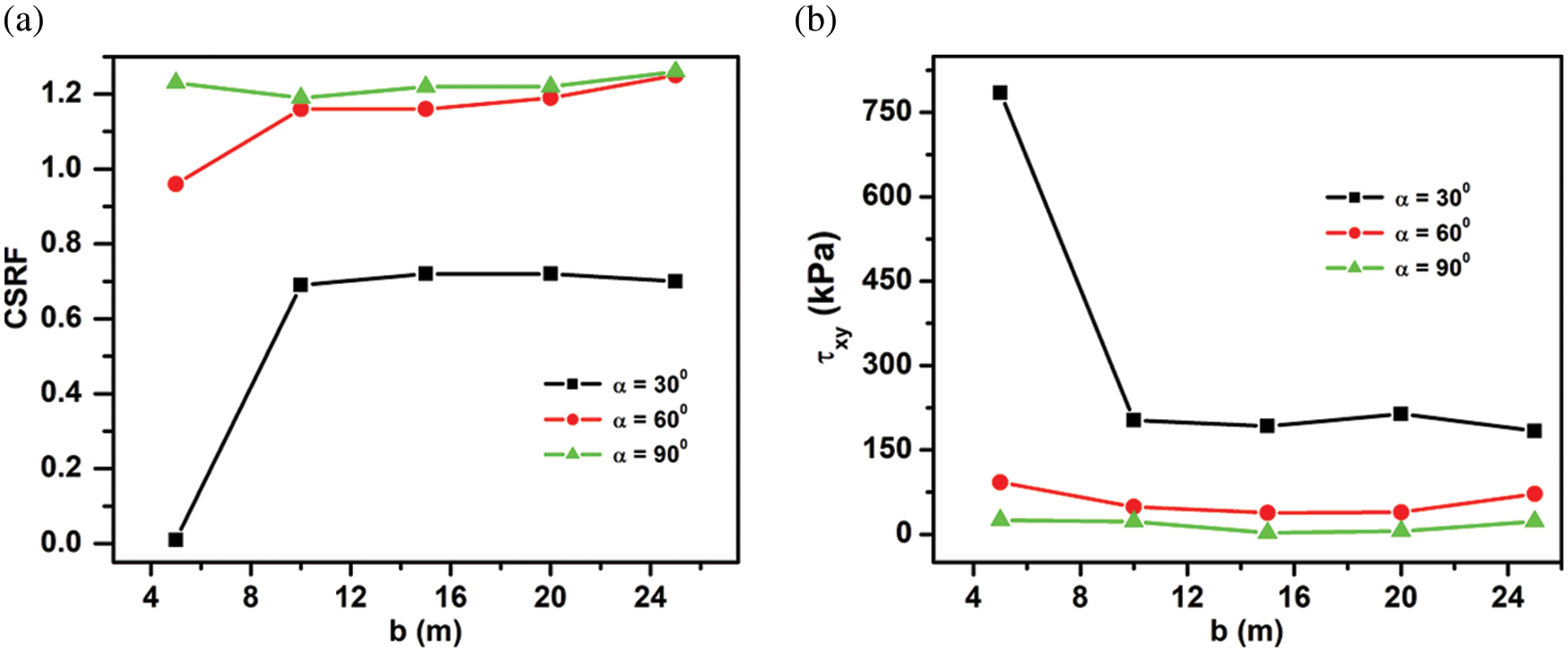
Figure 5: (a) Variation of CSRF vs. crest distance
Fig. 6 shows the Critical Slip Surface’s behaviour (CSS) function
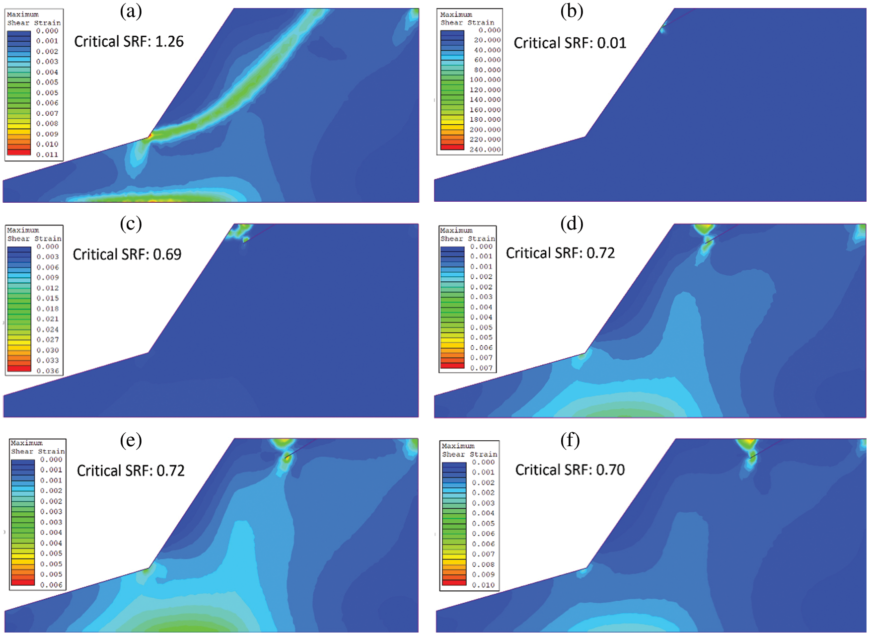
Figure 6: Location of CSRF with crest distance
The effect of critical crack length dc vs b of a vertical crack (
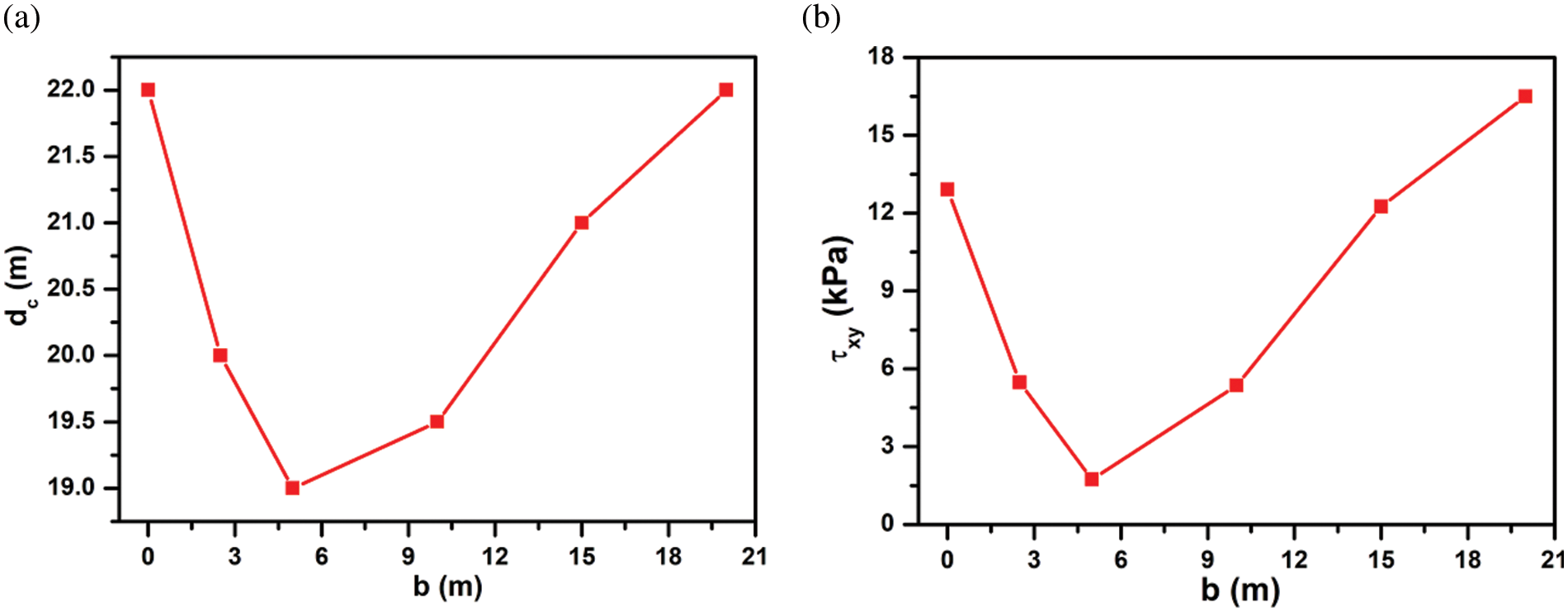
Figure 7: (a) Variation of critical crack length
5 Effect of Inclination Angle of a Joint on CSRF
We have also studied the joint’s effect on the rock slope’s stability. In the numerical simulations, a TC is replaced with a joint in which free surfaces now interact with each other via shear and normal forces [6]. The slope model is shown in Fig. 2 and is also used to investigate the effect of the inclination angle
The results of numerical simulations are shown in Fig. 8a shows CSRF vs.
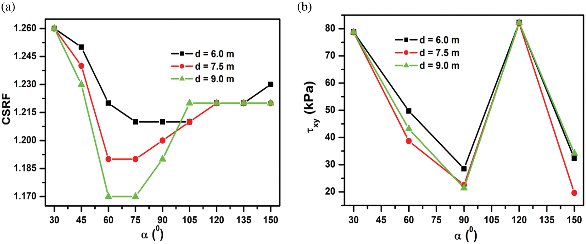
Figure 8: (a) Effect of the inclination angle of the joint on CSRF; (b) The corresponding variation of shear stress near the joint’s tip, at varying initial joint lengths = 6.0, 7.5 and 9.0 m and at a fixed crest distance = 10.0 m
We have also studied the corresponding shear stress
The effect of CSS has also been noticed in Fig. 9. For example, a joint α = 30°, as shown in Fig. 9b. indicates that the shear failure zone is still localized at the toe of the slope, and CSS does not interact with the joint. Hence, there is no reduction in CSRF as compared to Fig. 9a without a joint. However, for the joint with
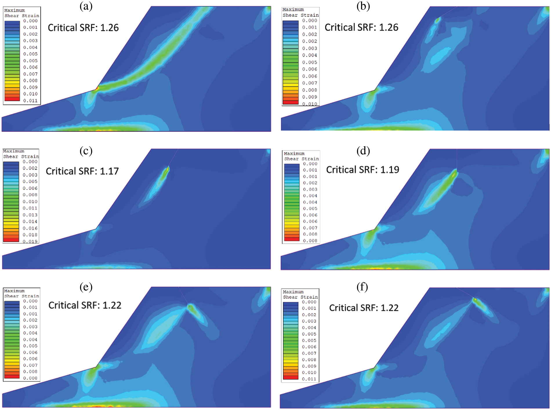
Figure 9: Location of CSRF with (a) no joint (b)
Although present numerical results are discussed in view of the magnitude and location of CSRF and the size of the failure zone, further study will be interesting to correlate them. Finally, it would also be interesting to carry out a three-dimensional analysis of a rock slope in the presence of both tension cracks and joints [23,29–31].
The present numerical study establishes that failure of the rock slope in the presence of an inclined TC results in a change of both magnitude and location of the Critical Strength Reduction Factor. In some instances, inclined tension cracks are more prone to failure than vertical TC. Nevertheless, all TCs are not sensitive to CSRF unless they exceed their critical length. A few cases have observed that a TC’s distance from the slope’s crest does not significantly affect CSRF and its location. It is also observed that the length of a TC is more sensitive to CSRF than its crest distance. The results indicate that regardless of the critical slip surface shape and magnitude, a smaller CSRF/FoS will be expected when TC dominates the failure surface.
Further, when a TC is replaced with a joint in the slope, the magnitude of CSRF and shear stress are quite different from the corresponding TC. Finally, it is believed that the present study will be very useful in analyzing the slope stability of jointed rock mass of the benches in opencast mines in the presence of tension crack. The above study will be useful in deciding the ultimate limit of pit slopes for safer working in opencast mines.
Acknowledgement: We would like to acknowledge the Director, Visvesvaraya National Institute of Technology, Nagpur, India, for his permission to publish this paper.
Funding Statement: The authors received no specific funding for this study.
Conflicts of Interest: The authors declare that they have no conflicts of interest to report regarding the present study.
References
1. N. Bar and N. Barton, “The Q-slope method for rock slope engineering,” Rock Mechanics and Rock Engineering, vol. 50, no. 12, pp. 3307–3322, 2017. [Google Scholar]
2. H. H. Einstein, “Risk and risk analysis in rock engineering,” Tunnelling and Underground Space Technology, vol. 11, no. 2, pp. 141–155, 1996. [Google Scholar]
3. P. Paronuzzi and A. Bolla, “Gravity-induced fracturing in large rockslides: possible evidence from vajont,” Engineering Geology for Society and Territory, vol. 2, pp. 213–216, 2015. [Google Scholar]
4. D. Stead and A. Wolter, “A critical review of rock slope failure mechanisms: The importance of structural geology,” Journal of Structural Geology, vol. 74, pp. 1–23, 2015. [Google Scholar]
5. D. Stead, E. Eberhardt and J. S. Coggan, “Developments in the characterization of complex rock slope deformation and failure using numerical modelling techniques,” Engineering Geology, vol. 83, no. 1–3, pp. 217–235, 2006. [Google Scholar]
6. K. Zhang, P. Cao, J. Meng, K. Li and W. Fan, “Modeling the progressive failure of jointed rock slope using fracture mechanics and the strength reduction method,” Rock Mechanics and Rock Engineering, vol. 48, no. 2, pp. 771–785, 2015. [Google Scholar]
7. B. Azarfar, S. Ahmadvan, J. Sattarvand and B. Abbasi, “Stability analysis of rock structure in large slopes and open-pit mine: Numerical and experimental fault modeling,” Rock Mechanics and Rock Engineering, vol. 52, no. 12, pp. 4889–4905, 2019. [Google Scholar]
8. I. Satyanarayana, G. Budi and S. Murmu, “Stability analysis of a deep highwall slope using numerical modelling and statistical approach—a case study,” Arabian Journal of Geosciences, vol. 14, no. 3, pp. 1–12, 2021. [Google Scholar]
9. I. Satyanarayana and G. Budi, “Analytical and numerical approach for analysis of factors affecting pit slope stability at dorli ocp-ii, India,” Journal of Mining Science, vol. 55, no. 3, pp. 376–382, 2019. [Google Scholar]
10. S. J. Martel, “Mechanics of landslide initiation as a shear fracture phenomenon,” Marine Geology, vol. 203, no. 3–4, pp. 319–339, 2004. [Google Scholar]
11. E. Eberhardt, D. Stead and J. S. Coggan, “Numerical analysis of initiation and progressive failure in natural rock slopes—the 1991 Randa rockslide,” International Journal of Rock Mechanics and Mining Sciences, vol. 41, no. 1, pp. 69–87, 2004. [Google Scholar]
12. R. Baker, “Tensile strength, tension cracks, and stability of slopes,” Soils and Foundations, vol. 21, no. 2, pp. 1–17, 1981. [Google Scholar]
13. W. M. Cai, V. Murti and S. Valliappan, “Slope stability analysis using fracture mechanics approach,” Theoretical and Applied Fracture Mechanics, vol. 12, no. 3, pp. 261–281, 1990. [Google Scholar]
14. F. H. Lee, K. W. Lo and S. L. Lee, “Tension crack development in soils,” Journal of Geotechnical Engineering, vol. 114, no. 8, pp. 915–929, 1988. [Google Scholar]
15. S. Sharma, T. K. Raghuvanshi and R. Anbalagan, “Plane failure analysis of rock slopes,” Geotechnical & Geological Engineering, vol. 13, no. 2, pp. 105–111, 1995. [Google Scholar]
16. L. Tang, Z. Zhao, Z. Luo and Y. Sun, “What is the role of tensile cracks in cohesive slopes?,” Journal of Rock Mechanics and Geotechnical Engineering, vol. 11, no. 2, pp. 314–324, 2019. [Google Scholar]
17. T. K. Raghuvanshi, “Plane failure in rock slopes–a review on stability analysis techniques,” Journal of King Saud University–Science, vol. 31, no. 1, pp. 101–109, 2019. [Google Scholar]
18. I. Satyanarayana, G. Budi, P. Sen and A. K. Sinha, “Stability evaluation of highwall slope in an opencast coal mine-a case study,” AMSE Journals-AMSE Iieta Publication, vol. 78, pp. 253–273, 2018. [Google Scholar]
19. D. Verma, R. Thareja, A. Kainthola and T. N. Singh, “Evaluation of open pit mine slope stability analysis,” International Journal of Earth Sciences and Engineering, vol. 4, no. 4, pp. 590–600, 2011. [Google Scholar]
20. S. V. Tsirel, A. A. Pavlovich, N. Y. Mel’nikov and B. Y. Zuev, “Physical modeling of deformation processes in pit slope with steep bedding,” Journal of Mining Science, vol. 55, no. 3, pp. 364–370, 2019. [Google Scholar]
21. S. Nunoo, “Lessons learnt from open pit wall instabilities: case studies of bc open pit hard rock mines,” Journal of Mining Science, vol. 54, no. 5, pp. 804–812, 2018. [Google Scholar]
22. E. M. Dawson, W. H. Roth and A. Drescher, “Slope stability analysis by strength reduction,” Geotechnique, vol. 49, no. 6, pp. 835–840, 1999. [Google Scholar]
23. W. B. Wei, Y. M. Cheng and L. Li, “Three-dimensional slope failure analysis by the strength reduction and limit equilibrium methods,” Computers and Geotechnics, vol. 36, no. 1–2, pp. 70–80, 2009. [Google Scholar]
24. V. B. Maji, “An insight into slope stability using strength reduction technique,” Journal of the Geological Society of India, vol. 89, no. 1, pp. 77–81, 2017. [Google Scholar]
25. G. You, M. Al Mandalawi, A. Soliman, K. Dowling and P. Dahlhaus, “Finite element analysis of rock slope stability using shear strength reduction method,” in Proc. of Int. Congress and Exhibition Sustainable Civil Infrastructures: Innovative Infrastructure Geotechnology, Cham, Springer, pp. 227–235, 2017. [Google Scholar]
26. Y. M. Cheng, T. Lansivaara and W. B. Wei, “Two-dimensional slope stability analysis by limit equilibrium and strength reduction methods,” Computers and Geotechnics, vol. 34, no. 3, pp. 137–150, 2007. [Google Scholar]
27. Rocscience, Phase2 V9.0/Rocscience, A two-dimensional finite element analysis of soil and rock for underground and excavated slopes, user’s manual. Toronto: RocScience Inc, 2014. [Google Scholar]
28. Z. Ahmed, S. Wang, O. H. Jasim, Y. Xu and P. Wang, “Variability effect of strength and geometric parameters on the stability factor of failure surfaces of rock slope by numerical analysis,” Arabian Journal of Geosciences, vol. 13, no. 21, pp. 1–12, 2020. [Google Scholar]
29. Q. Wu, Z. Kou and S. Wan, “Numerical simulation for the effect of joint inclination to the stability of stratified rock slope,” in 2012 Int. Conf. on Computer Application and System Modeling (ICCASM 2012), Atlantis Press, vol. 21, pp. 29–32, 2012. https://dx.doi.org/10.2991/iccasm.2012.8. [Google Scholar]
30. K. Ma, C. A. Tang, L. C. Li, P. G. Ranjith, M. Cai et al., “3D modeling of stratified and irregularly jointed rock slope and its progressive failure,” Arabian Journal of Geosciences, vol. 6, no. 6, pp. 2147–2163, 2013. [Google Scholar]
31. A. Z. Zhou, G. Liu, X. W. Huang, P. M. Jiang and Y. Chen, “Stability analysis of a two-layered slope with cracks by finite element limit analysis,” Advances in Civil Engineering, vol. 881227, no. 5, pp. 1–15, 2020. [Google Scholar]
Cite This Article
 Copyright © 2023 The Author(s). Published by Tech Science Press.
This work is licensed under a Creative Commons Attribution 4.0 International License , which permits unrestricted use, distribution, and reproduction in any medium, provided the original work is properly cited.
 Downloads
 Citation Tools