
 Submit a Paper
 Propose a Special lssue
 Open Access
ARTICLE
Hybrid Multi-Object Optimization Method for Tapping Center Machines
1 Department of Electrical Engineering, National Kaohsiung University of Science and Technology, Kaohsiung, 807, Taiwan
2 Department of Intelligent Robotics, National Pingtung University, Pingtung, 900, Taiwan
3 Graduate Institute of Precision Manufacturing, National Chin-Yi University of Technology, Taichung, 411, Taiwan
* Corresponding Author: Po-Yuan Yang. Email:
Intelligent Automation & Soft Computing 2023, 36(1), 23-38. https://doi.org/10.32604/iasc.2023.031609
Received 22 April 2022; Accepted 12 July 2022; Issue published 29 September 2022
 View Full Text
 Download PDF
Abstract
This paper proposes a hybrid multi-object optimization method integrating a uniform design, an adaptive network-based fuzzy inference system (ANFIS), and a multi-objective particle swarm optimizer (MOPSO) to optimize the rigid tapping parameters and minimize the synchronization errors and cycle times of computer numerical control (CNC) machines. First, rigid tapping parameters and uniform (including 41-level and 19-level) layouts were adopted to collect representative data for modeling. Next, ANFIS was used to build the model for the collected 41-level and 19-level uniform layout experiment data. In tapping center machines, the synchronization errors and cycle times are important considerations, so these two objects were used to build the ANFIS models. Then, a MOPSO algorithm was used to search for the optimal parameter combinations for the two ANFIS models simultaneously. The experimental results showed that the proposed method obtains suitable parameter values and optimal parameter combinations compared with the non-systematic method. Additionally, the optimal parameter combination was used to optimize existing CNC tools during the commissioning process. Adjusting the proportional and integral gains of the spindle could improve resistance to deformation during rigid tapping. The position gain and pre-feedback coefficient can reduce the synchronization errors significantly, and the acceleration and deceleration times of the spindle affect both the machining time and synchronization errors. The proposed method can quickly and accurately minimize synchronization errors from 107 to 19.5 pulses as well as the processing time from 3,600 to 3,248 ms; it can also shorten the machining time significantly and reduce simultaneous errors to improve tapping yield, thereby helping factories achieve carbon reduction.Keywords
In the machining of parts, internal threading is usually the final process; therefore, high machining accuracy and stability are required to avoid scrapping of materials caused by errors during the tapping process. Hence, machining manufacturers need reliable and stable methods to maintain the quality of the threads, especially in mass production lines with internal threads in the case of parts. Welding, heat treatment, casting, and additive and subtractive processes are manufacturing procedures that play essential roles in all stages of machined part production. Traditional manufacturing processes typically include welding, heat treatment, and casting [1,2]. Additive processes can be employed to manufacture high-strength and lightweight products that are often used in producing automotive, aerospace, or biomedical parts [3–5]. Subtractive processes are employed to process hard and solid objects, so it is still the primary method used in the tapping process [6,7].
Accurate setting of suitable parameters during machining is crucial for product quality, productivity, and cost because the economics and process performance depend on these parameters. Cost reduction and quality improvement are necessary for improving the competitiveness of enterprise operations. In each tapping process, the accuracy depends largely on whether the tapping axis feed movement is synchronized well with the spindle rotation during the tapping cycle. The observed index of the tapping axis feed to spindle rotation is the synchronization error. The collocation of relevant spindle parameters and tapping axis directly affects the synchronization error results. It is our goal to minimize these synchronization errors through parameter adjustments. Studies on rigid tapping often include master-slave and imperative control methods. The master-slave control method uses the feed axis to follow the spindle position to achieve position correction. The command type compensates for the commands of the spindle and feed axis simultaneously. Another approach to reducing the rigid tapping synchronization errors involves improving the system responses of the spindle and feed axis through servo tuning. The present study aims to find the relationship between the synchronization errors and controller parameters in rigid tapping through different controller parameter settings. Moreover, the processing time specifically impacts workpiece quality and production profitability. Generally speaking, synchronization errors are related to the machining process, but the cycle time conflicts with the errors. This means that during tapping, the cycle time increases while the synchronization errors decrease. Therefore, this study solves for multiple-conflicting problems through the multi-objective optimization method, optimizes the tapping parameters, reduces errors, improves yield, and shortens the processing time.
For servo parameter commissioning, Lee et al. [8] proposed iterative measurement and simulation of the machine contour performance as well as adjusting the servo parameters to reduce vibration and improve contour accuracy. The Kreuz–Gitter–Meβsystem (KGM) method was used to measure the 2D contour performance of the machine with non-contact optics. Unlike the traditional double ball bar (DBB) method, which allows only circular testing, the KGM method enables measurement of any geometric shape. Yeh et al. [9] proposed a “learning automation” method that effectively adjusts the optimal control gain through a two-stage process. Yeh et al. [10] also proposed improvement of the profile and synchronization errors through cross-coupling control, a feedforward nonlinear friction compensator to compensate for nonlinear friction, and a disturbance observer to reduce the impact of external disturbances on the control system. Based on these techniques, the spindle speed is maintained at 6000 rpm, and the synchronization errors are less than 10 ums. Lu et al. [11] used a fuzzy adaptive proportional–integral–derivative (PID) method to control rigid tapping, where the fuzzy control is matched with PID control in the dynamic and static characteristics of the system. This method can be applied without establishing the controlled object, and the fuzzy inference model is used for PID parameter adjustment. To achieve higher manufacturing efficiency, Sencer et al. [12] proposed a cross-coupled controller to improve the differential positioning errors between dual servo drives by modifying the reference position and velocity commands; this approach improves motion synchronization without affecting the overall tracking bandwidth. Biris et al. [13] proposed a mathematical model based on the transfer function to adjust the machine feed-drive system and conducted experiments to compare the effectiveness of various methods for eliminating positioning and contour errors. Chen et al. [14] proposed an iterative learning control (ILC) algorithm to optimize the synchronization errors of rigid tapping; this algorithm provides better commands for z-axis and spindle motions, synchronizing their output responses as much as possible. Their experimental results show that the synchronization error decreases from 0.26 mm to 2.6 × 10⁻¹³ mm when the ILC is executed to the 10th learning cycle and that the error synchronization converges with increase in the number of learning cycles.
Chen et al. [15] proposed an intelligent computer-aided process planning (i-CAPP) method based on manufacturability and efficiency. When complex workpieces are processed and the complexity of processing increases, i-CAPP can be used to integrate intelligent functions and domain expertise for decision-making and program collaboration. Ma et al. [16] dynamically modeled the tapping process along the tapping path according to coupling between the radial and axial vibrations as well as dynamic cutting forces. The radial and axial chatter stability of the tapping process are predicted separately in the frequency domain to ensure thread wall quality and tapping life. In the authors’ previous study [17], a systematic approach was used to collect and model data, and an evolutionary algorithm was used to explore the optimal parameters. Although these studies are effective for reducing synchronization errors, they ignore another important output factor, namely the processing time, which may increase production costs owing to the cycle time involved in power consumption. In the current scenario of energy shortage and carbon dioxide emission reductions, the cycle time can be considered as one of the important outputs. In addition, reducing the cycle time can speed up overall processing. However, reductions of the processing time and synchronization errors are conflicting goals; to meet both goals simultaneously, a novel hybrid multi-object method is developed in this study while meeting their individual requirements.
The hybrid multi-object method proposed herein can be used to adjust the rigid tapping electronic control parameters such that the machining time and synchronization errors can be reduced effectively. The advanced hybrid approach is divided into three parts. First, a uniform design (UD) [18–21] was used to collect data. Then, a model using an adaptive network-based fuzzy inference system (ANFIS) [22–24] was built with the collected data. Finally, multi-objective evolutionary algorithms (MOEAs) [25–28] were used to explore a suitable combination of parameters considering quality and machining time. From the actual factory process results, the synchronization errors are reduced by 81.78% and machining time is reduced by 9.78%. Therefore, the method proposed in this study can be considered compelling.
The remainder of this manuscript is organized as follows. Section 2 briefly describes the problem considered in this study. Section 3 discusses the preliminaries, including the UD, ANFIS, and MOEAs. Section 4 presents and discusses the experimental and simulation results. Finally, Section 5 summarizes the conclusions of the study.
The operational objective of a processor is to maximize the profit of the finished product. The workpiece accuracy and processing time cost are key factors that affect profits. In this study, rigid tapping experimental data were collected through uniform layout experiments to examine the relationships between synchronization errors and cycle time via experimental design. Models were built to analyze the synchronization errors and cycle time data of the experiments. Finally, MOEAs were employed to find the best combination of cutting parameters with minor synchronization errors and shortest cycle time to increase production profits.
In recent years, given the advances in technology, the production and manufacturing of aerospace, electric vehicle molds, and bicycle components are moving towards higher precision and higher yields. Mold components require many internally threaded holes that are usually arranged in postproduction. The quality of tapping seriously affects product quality and cost; therefore, manufacturers need fast and reliable methods to process internally threaded holes.
Tapping can be classified into floating and rigid types. Rigid taps can be machined without special collets; however, floating taps require a different tool clamping device. The advantage of floating tapping is that it is easy to use and does not require complicated control theory. However, the main disadvantages of floating tapping are loose connections, which cause specific errors, and high tapping speed that causes severe vibration, resulting in inaccurate tapping or messy/broken teeth. Different floating tapping sleeve specifications also need to be replaced in accordance with the tapping ranges. In rigid tapping, high-speed and accurate tapping can be performed without floating tapping sleeves, and the tapping depth and speed are faster and more precise. However, synchronization between the spindle and tapping axis must be accurate as even minor differences can cause tool damage. Therefore, precise synchronization of the spindle and tapping axis is critical.
Based on the required pitch specifications, the matching ratio of the spindle speed and feed speed of the tapping axis is adjusted. This relationship can be expressed as in Eq. (1).
where P is the thread pitch (mm), F is the feed rate of the tapping axis (mm/min), and S is the spindle speed (rpm).
This experimental stage uses the FIRST VT-18 series tapping center machine with a FANUC 0iMD controller, whose control method identifies the synchronization error between the main shaft and tapping based on how the tapping axis follows the main shaft. Additionally, the FANUC 0iMD controller used in this experiment implements a control method in which the tapping axis follows the spindle and identifies synchronization errors between the spindle and tapping axis. If the synchronization error is too large, it will directly affect the thread pitch and diameter, resulting in disordered or broken teeth. Fig. 1 shows the measurements used for the analysis of the screw teeth. When rigid tapping is performed, the spindle and feed axis must maintain a specific proportional relationship. The performance index here is the synchronization error, which is the deviation between the actual positions of the spindle and feed axis, as shown in Eq. (2).
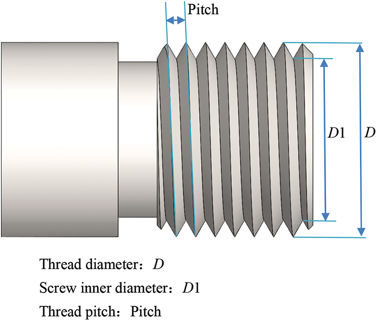
Figure 1: Measurements used for analysis of screw teeth
where errorsyn is the synchronization error, errors indicates the spindle position loop error, errorf denotes the feed axis position loop error, and a and b are the screw pitch and ball screw pitch, respectively.
This section briefly describes the methods applied in the modeling process, including the UD methods [18–21], ANFIS [22–24], and MOEAs [25–28].
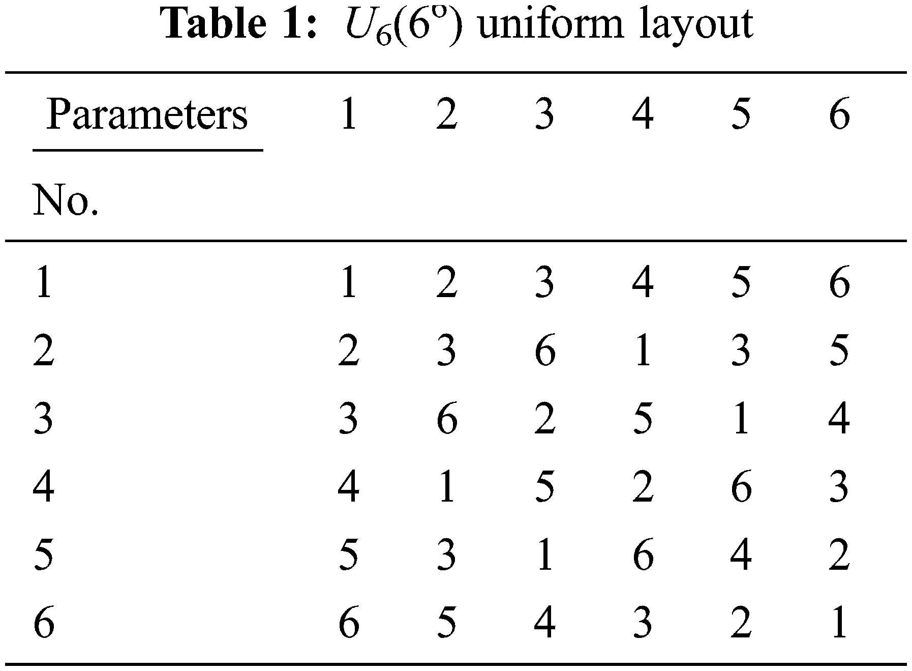
The UD method proposed by Fang and Wang [19–20] is used to design and arrange experiments where the test points are distributed evenly over the test range, making each data more representative. A uniform layout can be expressed as Un(ns), where U is the uniform layout, n is the level number, and s is the factor number. Tab. 1 shows the distribution of a U6(66) uniform layout, where the values in the content are the levels. The experimenter divides the given parameter range into levels based on the requirements of a uniform layout. The horizontal and vertical headers in Tab. 1 are the parameters and experimental combinations, respectively; accordingly, each parameter has six levels in the arrangement, and there are six combinations in this experimental layout. In this work, data collected by the UD method are used for model building, and data analysis is performed using ANFIS.
3.2 Adaptive Network-based Fuzzy Inference System (ANFIS)
ANFIS uses the self-learning ability of a neural network to adjust the attribution function and improve adaptability. The fuzzy inference rules enhance the inference ability of the neural network. ANFIS, which was proposed by Jang in 1993 [29], is a hybrid intelligence system that utilizes artificial neural networks (ANNs) and fuzzy logic theory. ANFIS can learn from training data using ANN techniques to update the parameters of the inference model. Therefore, the solution mapped to the fuzzy inference system (FIS) can be described descriptively. The ANFIS model is divided into five structural layers. The first layer is the input layer, where the input variables are mapped to the fuzzy sets; the second layer executes the rule layer, which combines and pairs fuzzy sets among the input variables and then performs fuzzy logic operations; the third layer allows normalization of the attribution function. The fourth layer is the defuzzification layer, which enables inferring the results. The fifth layer sums up the individual outputs. In the ANFIS model, the numbers and types of input and output membership functions (MF) are first defined and then trained with the training dataset. The output and input MF parameters can be changed during the learning process.
3.3 Multi-Objective Evolutionary Algorithms (MOEAs)
Most evolutionary algorithms (EAs) search for solutions to a single objective. Under the single objective condition, EAs explore suitable answers to the issues. If there are two or more objectives (multi-objective) to an issue, a conflict may exist between them. Therefore, solutions must be found for two objectives. Pareto [30] first proposed the Pareto Optimum, which has since then allowed multi-objective optimization. On practical issues, it is not uncommon for two objectives to be considered, including design [31], water treatment [32], energy arrangements [33], and scheduling [34]. The commonly used MOEAs include multi-objective particle swarm optimizer (MOPSO) [25,26], non-dominated sorting genetic algorithm-II (NSGA-II) [27], and multi-objective differential evolution (MODE) [28]. The MOPSO algorithm was proposed by Coello et al. in 2002 [25,26] by combining the Pareto envelope and grid-making technology to handle multi-objective optimization problems. NSGA-II was proposed by Deb [27], where a fast non-dominated sorting method and crowding mechanism are used to improve the complexity and sorting method as well as introduce an elitist strategy. The update method of differential evolution (DE) is similar to that of the genetic algorithm (GA), but the DE pays more attention to mutation, whose operation is performed first. For multi-objective issues, Huang et al. proposed MODE [28], which improves the crowding mechanism, introduces a time-varying scaling vector, and adopts a variation factor.
4 The Hybrid Multi-Object Optimization Method for Tapping Center Machines
The UD method was used to collect experimental data in this study. ANFIS was used to establish the objective function model, in which the max-min algorithm was used for the fuzzy inference operation. A Gaussian MF was used to model the synchronization errors and machining times when training the ANFIS models. The MOPSO algorithm was used on the multi-objective function to obtain the optimal multi-objective solution.
From bicycle components to consumer goods, such as mobile phones and laptops, many drilling and tapping processes are required in the manufacturing of molds. There are also different hole sizes according to the design requirements of different parts. It is therefore necessary to determine the parameter combination that provides the best tapping accuracy and shortest machining time while achieving high product quality in postprocessing. Hence, the objective of this study was to find the parameter combination that minimized rigid tapping synchronization errors and manufacturing times. Fig. 2 shows the VT-18 series tapping center machine (Long Chang machinery industries Co., Ltd.) with a FANUC 0iMD controller on which the experiments were performed. The test cutting conditions were as follows. Spindle speed, tapping axis feed rate, and tapping depth were set to 3000 rpm, 3000 mm/min, and 50 mm, respectively. The experiments were performed three times using these settings, and Fig. 3 shows the processing path.
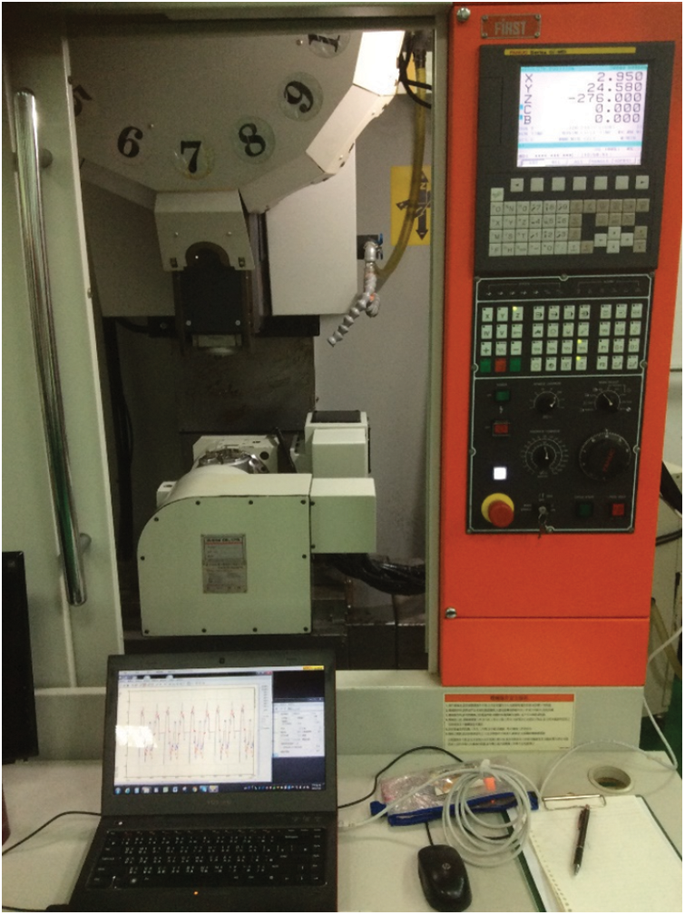
Figure 2: Tapping center machine (FIRST VT-18 series) used in the experiments
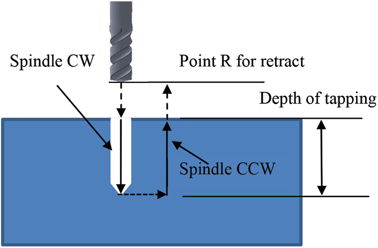
Figure 3: Diagram of rigid tapping path relationship
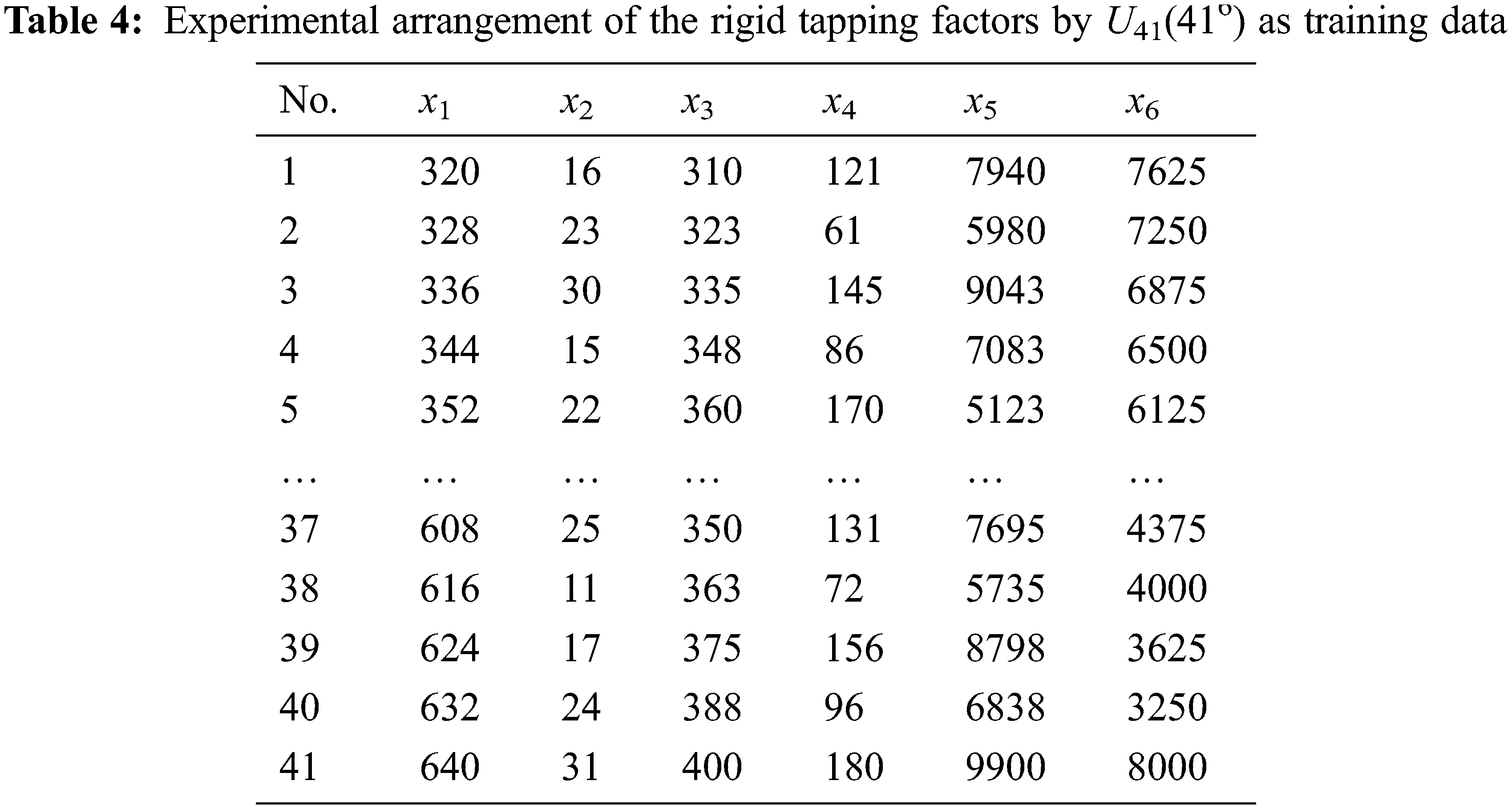
The experimental inputs are the factors that affect synchronization error and machining time. The outputs are the synchronization error and machining time. The input factors that affect synchronization error and machining time include the time constant for acc./dec. in rigid tap (x1), rigid tapping speed loop proportional gain (x2), motor excitation delay time (x3), rigid tapping speed loop integral gain (x4), advanced preview feed-forward coefficient (x5), and tapping axis position gain (x6) [35–38].
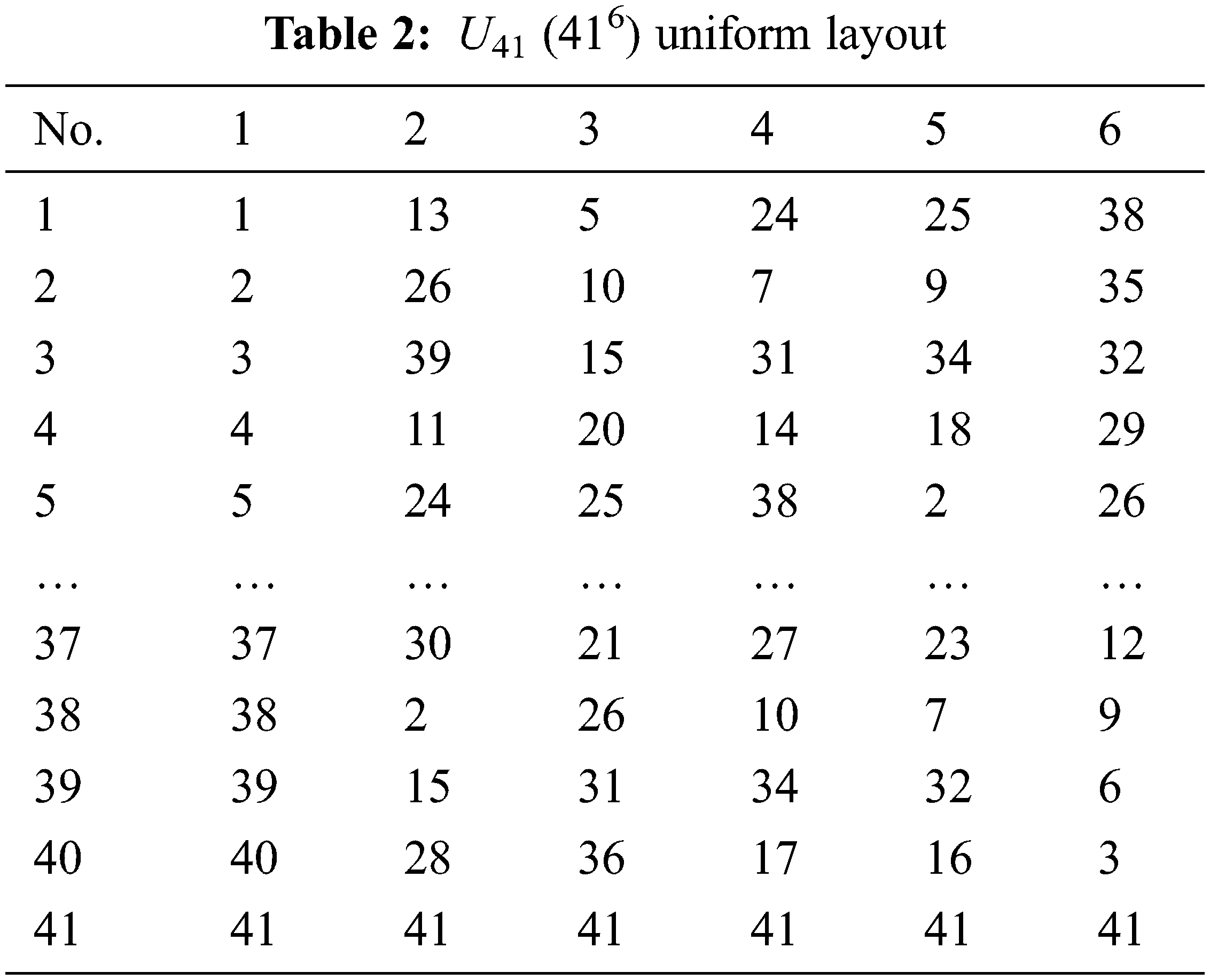
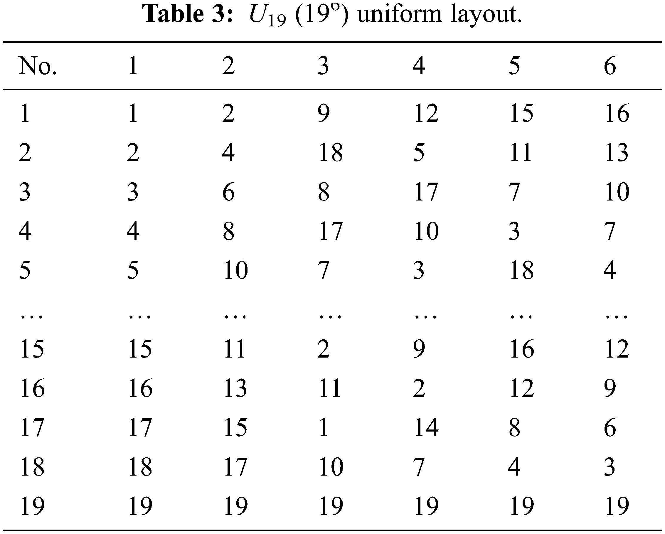
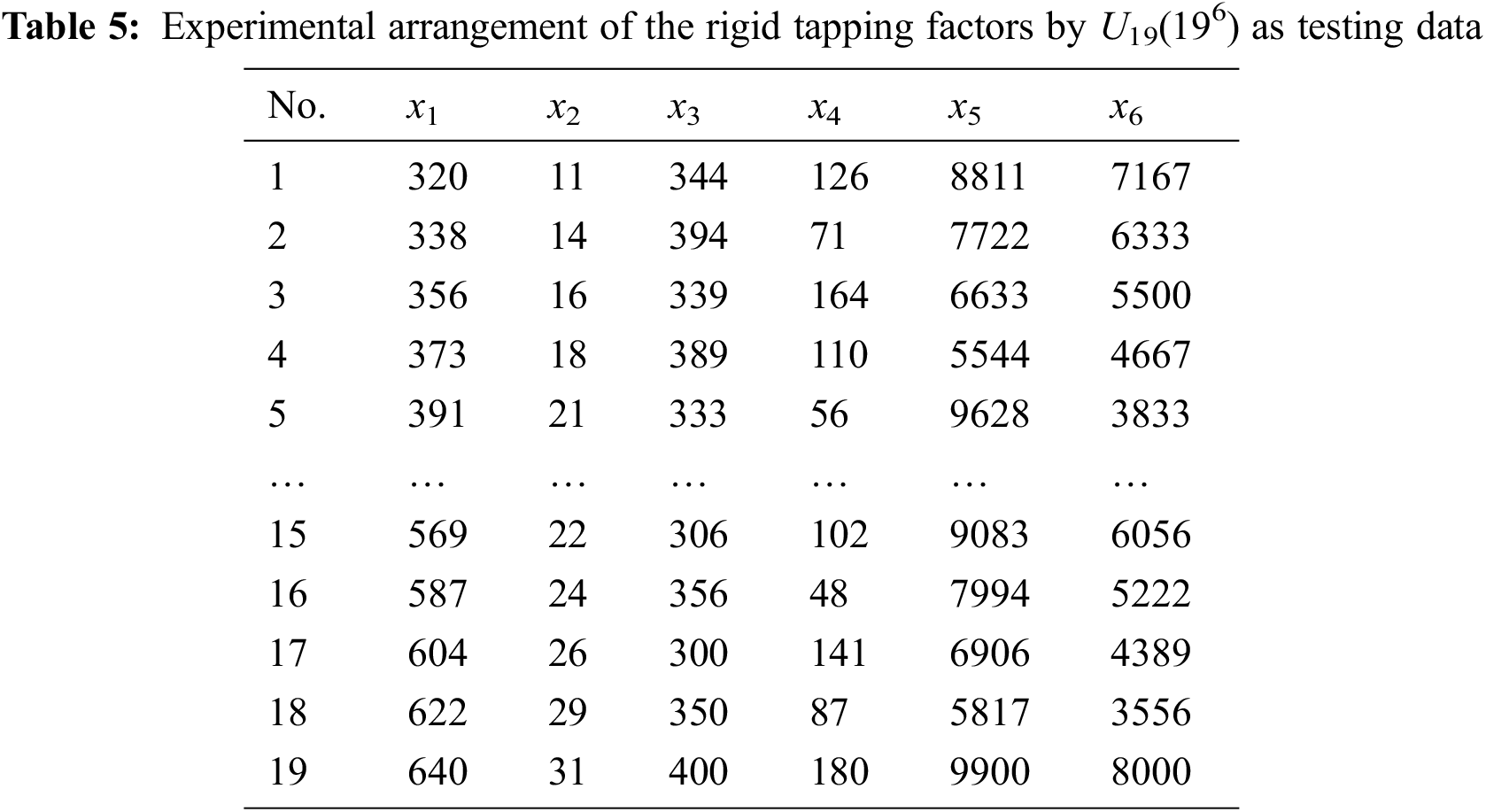
Fig. 4 shows the experimental procedure. The uniform distribution characteristic of the UD allowed each experimental combination to be meaningful, which substantially reduced the required number of experiments; hence, uniform layouts were used in this work to collect data for modeling. Tabs. 2 and 3 show the U41(416) and U19(196) uniform layouts selected for modeling. From Fig. 4, six input factors were first entered in the U41 uniform layout; the synchronization error and machining time were the quality characteristics, and the response value was obtained based on the-smaller-the-better characteristic. Tabs. 4 and 5 show the 41 and 19 levels for each of the parameters. A servo guide (SG) software was used to observe the results (synchronization error and machining time) of the tapping experiments performed using the factor combinations in Tab. 3. Tabs. 6 and 7 display the results from the experimental layouts of Tabs. 4 and 5, respectively.
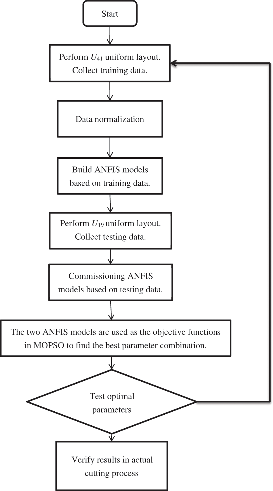
Figure 4: Flowchart of experimental procedure
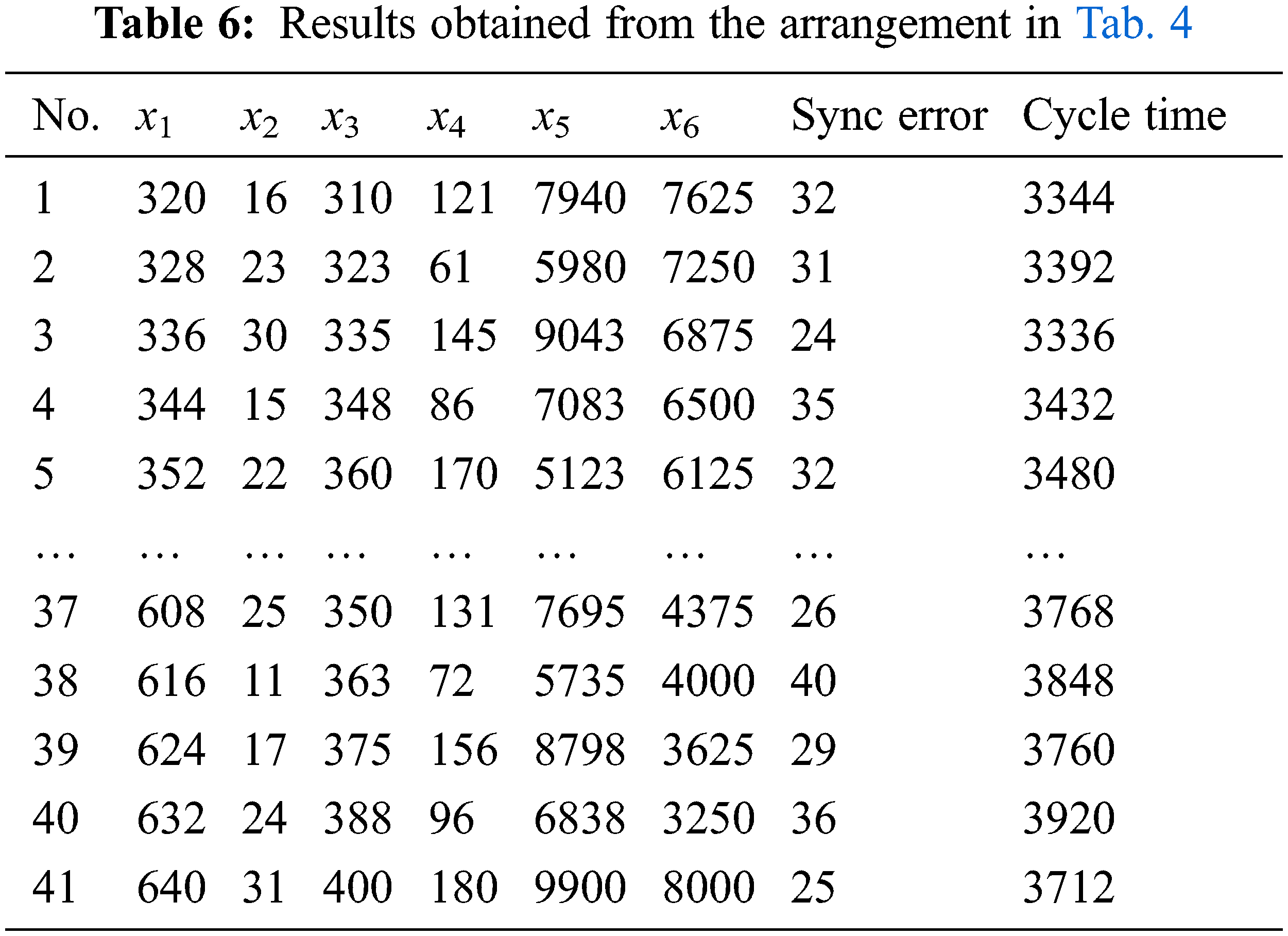
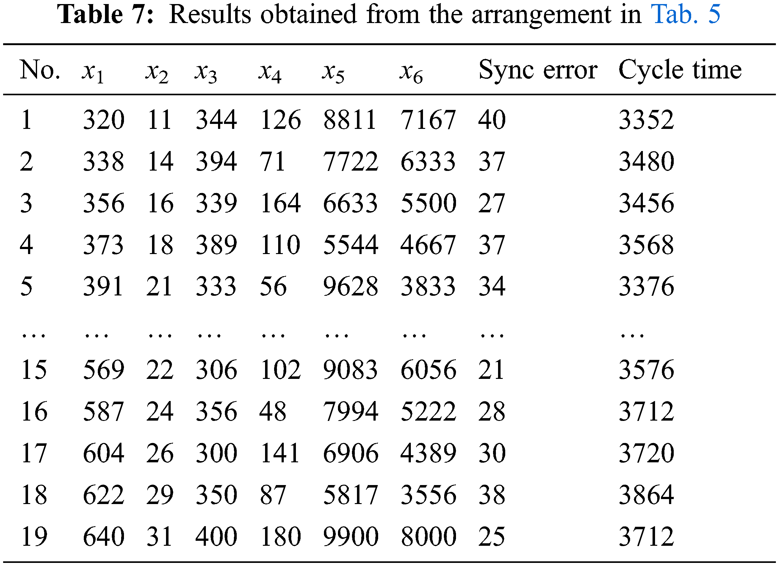
Tabs. 6 and 7 present the results obtained for the U41(416) and U19(196) uniform layouts, respectively. In this work, we considered the results of Tab. 6 as the input data for ANFIS modeling to train and built a better model by fine-tuning the MFs. Then, the results from Tab. 7 were used as the testing data. The ANFIS model target is a smaller RMSE (root-mean-square error) value, which is considered to be better. Fig. 5 is the diagram of the ANFIS model structure used in this study. Fig. 5 shows the input data (x1, x2, x3, x4, x5, and x6) applied to the input layer, using which the MFs of each input are set. The number of MFs are set as three for each parameter in this work, and each MF is of the Gaussian type. The output layer shows the results of the fuzzification, normalization, and defuzzification layers. Two ANFIS models were built here for the two objectives. Their MFs according to the data are different, as shown in Fig. 6. From the results, the RMSE of the model using training data, with cycle time as the objective, is 1.1343 × 10⁻³, and that using testing data is 0.15585. With the synchronization error as the objective, the RMSE of the model using training data is 6.1939 × 10⁻⁵ and that using testing data is 0.40605.
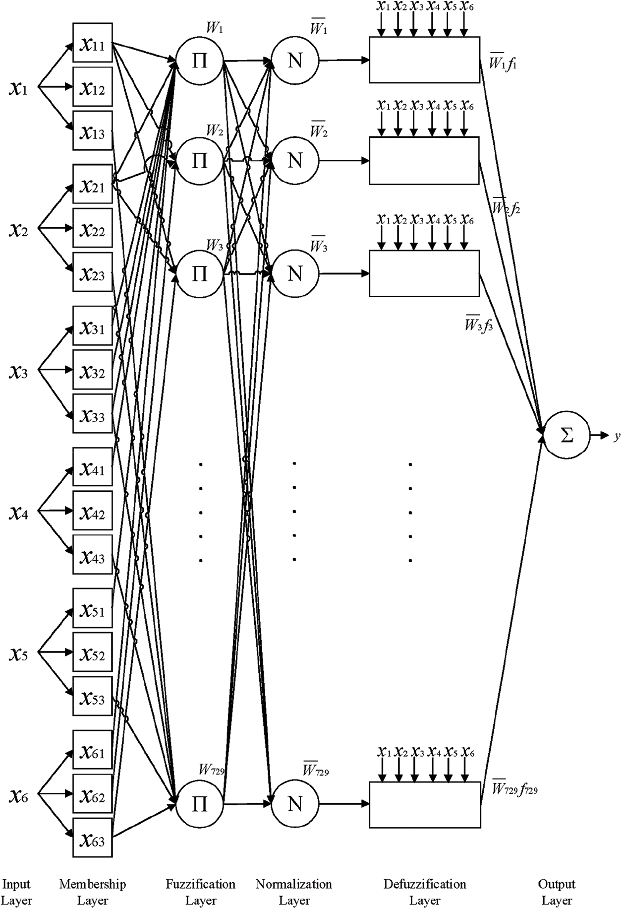
Figure 5: ANFIS model structure based on data
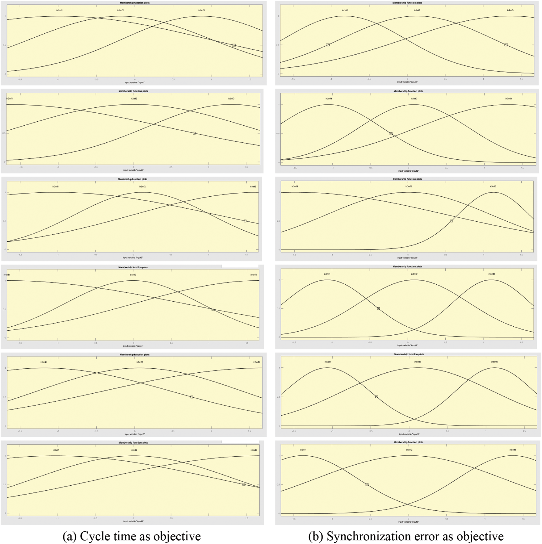
Figure 6: Membership functions for six parameters for ANFIS modeling
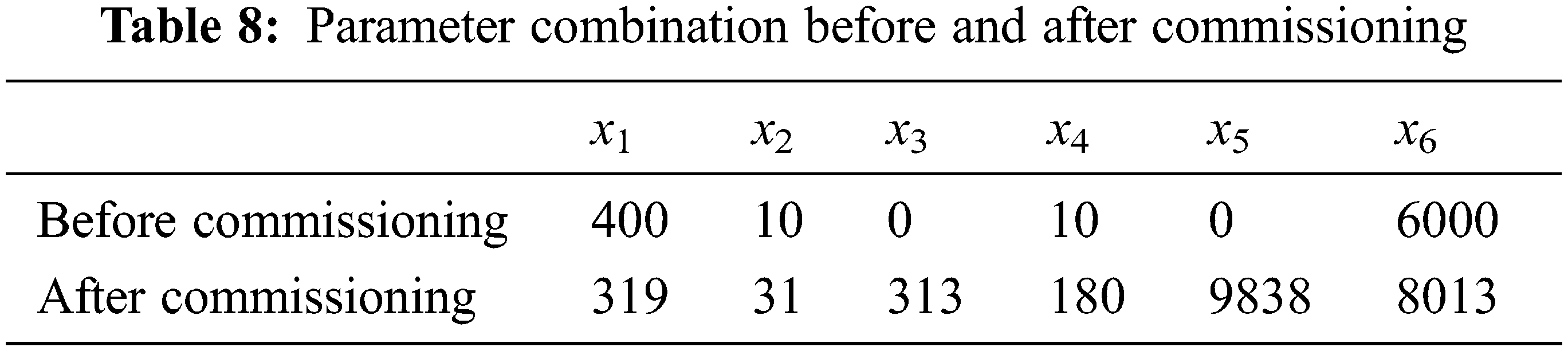
Next, this work uses MOEAs to explore the optimal multi-object combination of values for factors x1, x2, x3, x4, x5, and x6 based on the models built using ANFIS. The MOEAs used in this work include MOPSO, NSGA-II, and MODE. For verification of the performances among MOPSO, NSGA-II, and MODE, a total of 200 parameter combinations were obtained using the three methods. MOPSO has 110 combinations with better output values than those before commissioning; MODE has 62 combinations, and NSGA-II has only 32 combinations. Therefore, MOPSO was considered as the exploration method here and used to explore the optimal multi-object combination of values for factors x1, x2, x3, x4, x5, and x6. According to the MOPSO results, one of the optimal global combinations of minimum synchronization error and cycle time was (x1, x2, x3, x4, x5, x6) = (319, 31, 313, 180, 9838, 8013), and its optimal output values were 19.5 pulses and 3,248 ms for the synchronization errors and cycle time, respectively.
Fig. 7 shows the rigid tapping errors and machining time obtained with the optimal parameter combination. In Fig. 7, the horizontal and vertical coordinates represent time and synchronization error, respectively. The synchronization error was 107 pulses before adjustment and 19.5 pulses after adjustment. The machining times were 3,600 and 3,248 ms before and after adjustment, respectively. Tab. 8 shows the parameter combinations before and after commissioning (optimization). The simulation results and actual processing results were compared before and after optimization for verification. The optimal combination was then used in an actual thread cutting process. After performing the process three times, its synchronization error and machining time were observed. The SG software was used in this study to record and measure the synchronization errors and machining time precisely.
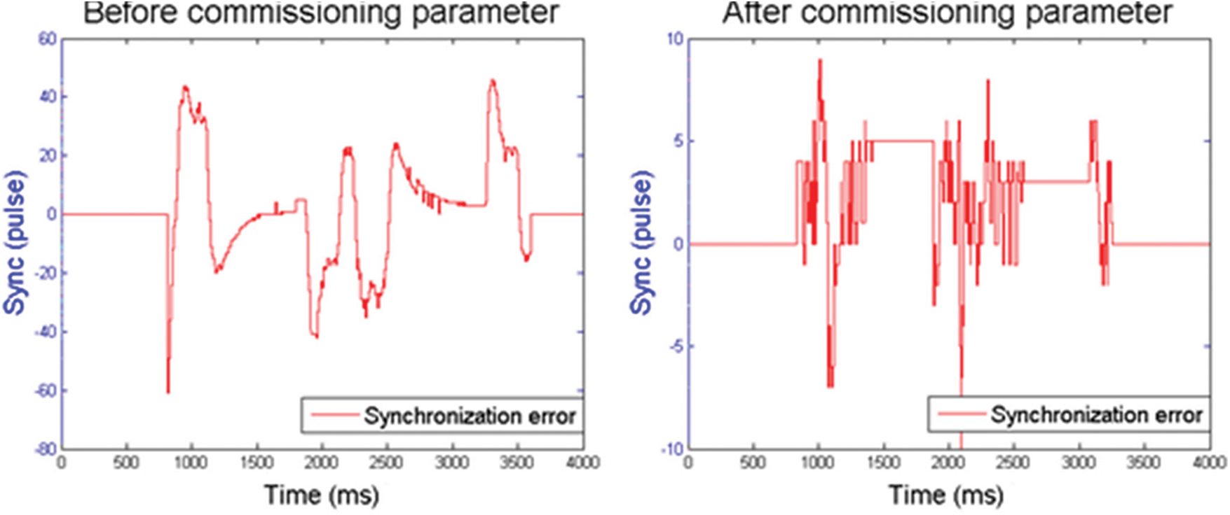
Figure 7: Synchronization error waveforms for rigid tapping before and after commissioning
An actual thread cutting process was used to verify the proposed hybrid method for optimizing synchronization errors and machining time in rigid tapping. The optimal combinations of parameters were explored by adjusting the parameter values and recording the synchronization error and machining time of the spindle and tapping axis. Rigid tapping can be performed straightforwardly when spiral tapping is operated in CNC machine at the expected speed and feed rate. However, to achieve high-quality rigid tapping, a high synchronization of motion is required to avoid damage to the tapping tool and the workpiece. Therefore, the UD method proposed in this study integrated ANFIS and MOPSO for synchronization error and machining time optimizations of the rigid tapping parameters and to obtain excellent tapping results.
The optimal combination of values for the parameters x1, x2, x3, x4, x5, and x6 was 319, 31, 313, 180, 9838, and 8013, respectively. Based on his combination, the synchronization error could be reduced from 107 pulses to 19.5 pulses, which is an 81.78% improvement of accuracy. Using this combination, the processing time could be reduced from 3,600 to 3,248 ms, which is a 9.78% improvement in machining time.
The proposed method improves the machining accuracy and machining time based on the optimum of the rigid tapping parameters. In addition, the proposed method reduces the possibility of damaging the workpiece pending the tapping process and reduces the time required for parameter tuning. The four main findings of the experiments are as follows:
1. Adjusting the proportional and integral gains of the spindle can increase the rigidity during rigid tapping.
2. The synchronization errors can be significantly decreased by adjusting the tapping axis’s position gain and feed-forward coefficient. The synchronization error is tiny, but the current increases when the position gain is considerable. As mentioned in the authors’ previous study [17], the current value should not exceed 70%–80% in the course of air cut commissioning and overheating or overloading the motor should be avoided by setting a reserved space during the actual cutting.
3. The initial errors of rigid tapping and the machining time can be reduced and possibly increased, respectively, through adjustment of the time required for motor excitation and stabilization.
4. Adjusting the acceleration/deceleration time constant of rigid tapping significantly affects the synchronization error and machining time. Increasing the acceleration/deceleration time constant can reduce synchronization errors but also increase machining time significantly.
The proposed method significantly reduces synchronization errors and machining time. However, when different conditions are used for rigid tapping, re-experiments are needed, which may require additional time. In the future, it the proposed method can be optimized to reduce the number of experiments and provide more real applications. According to the current plan, two objective functions are modeled before applying to the multi-objective model; in the future, these can be integrated into a single objective function for modeling.
Acknowledgement: This work was supported in part by the Ministry of Science and Technology, Taiwan, under Grant Numbers MOST 110-2221-E-153-010.
Funding Statement: Publication costs are funded by the Ministry of Science and Technology, Taiwan, under Grant Numbers MOST 110-2221-E-153-010.
Conflicts of Interest: The authors declare that they have no conflicts of interest to report regarding the present study.
References
1. B. Tomar, S. Shiva and T. Nath, “A review on wire arc additive manufacturing: Processing parameters, defects, quality improvement and recent advances,” Materials Today Communications, vol. 31, no. 1, pp. 103739, 2022. [Google Scholar]
2. J. P. Oliveira, A. D. LaLonde and J. Ma, “Processing parameters in laser powder bed fusion metal additive manufacturing,” Materials & Design, vol. 193, pp. 108762, 2020. [Google Scholar]
3. I. Hernandez-Carrillo, C. J. Wood and H. Liu, “Advanced materials for the impeller in an ORC radial microturbine,” Energy Procedia, vol. 129, pp. 1047–1054, 2017. [Google Scholar]
4. T. Yamazaki, “Development of a hybrid multi-tasking machine tool: Integration of additive manufacturing technology with CNC machining,” Procedia CIRP, vol. 42, pp. 81–86, 2016. [Google Scholar]
5. G. Żywica, P. Bagiński and A. Andrearczyk, “A new method of manufacturing a foil bearing using tools made by the rapid prototyping technology,” CIRP Journal of Manufacturing Science and Technology, vol. 31, no. 3, pp. 514–524, 2020. [Google Scholar]
6. P. Kosky, R. Balmer, W. Keat and G. Wise, “Chapter 12 - Manufacturing engineering,” in Exploring Engineering: An Introduction to Engineering and Design, 5th ed., London, UK: Academic Press, pp. 259–291, 2021. [Google Scholar]
7. I. Hutchings and P. Shipway, “Chapter 9 - Applications and case studies,” in Tribology, 2nd ed., Oxford, UK: Butterworth-Heinemann, pp. 303–352, 2017. [Google Scholar]
8. K. Lee, S. Ibarakil, A. Matsubara, Y. Kakino, Y. Suzuki et al., “A servo parameter tuning method for highspeed NC machine tools based on contouring error measurement,” WIT Transactions on Engineering Sciences, vol. 44, pp. 1–12, 2003. [Google Scholar]
9. S. Yeh and J. Lee, “Optimal tuning of control gains for rigid tapping processes using a learning automata methodology,” in 2015 IEEE Congress on Evolutionary Computation (CEC), Sendai, Japan, pp. 3248–3255, 2015. [Google Scholar]
10. C. F. Yeh, W. S. Huang, C. H. Kuo and P. L. Hsu, “Design and applications of the synchronized motion controller for tapping processes,” in 2012 XXth Int. Conf. on Electrical Machines, Marseille, France, pp. 143–149, 2012. [Google Scholar]
11. J. Lu, H. X. Zou, L. Shen and X. J. Zou, “Application of adaptive fuzzy-PID control in servo spindle rigid tapping,” Advanced Materials Research, vol. 301–303, pp. 1477–1481, 2011. [Google Scholar]
12. B. Sencer, K. Ishizaki and E. Shamoto, “Cross coupling controller for accurate motion synchronization of dual servo systems,” International Journal of Automation Technology, vol. 7, no. 5, pp. 514–522, 2013. [Google Scholar]
13. C. Biris, R. Breaz, C. Girjob and A. Chicea, “Researches regarding optimising the contouring precision of CNC laser cutting machines,” Applied Mechanics and Materials, vol. 555, pp. 580–585, 2014. [Google Scholar]
14. S. -L. Chen, C. -I. Pan and C. -Y. Chou, “Reduction of synchronous errors in rigid tapping by iterative learning control,” in 2012 IEEE/ASME Int. Conf. on Advanced Intelligent Mechatronics (AIM), Kaohsiung, Taiwan, pp. 467–471, 2012. [Google Scholar]
15. C. -S. Chen and Y. T. A. Sun, “Intelligent computer-aided process planning of multi-axis CNC tapping machine,” IEEE Access, vol. 5, pp. 2913–2920, 2017. [Google Scholar]
16. Y. -C. Ma, M. Wan, Y. Yang and W. -H. Zhang, “Dynamics of tapping process,” International Journal of Machine Tools and Manufacture, vol. 140, no. 9, pp. 34–47, 2019. [Google Scholar]
17. P. -Y. Chang, P. -Y. Yang, S. -H. Chen and J. -H. Chou, “Hybrid optimization method for correcting synchronization errors in tapping center machines,” Applied Sciences, vol. 11, no. 8, pp. 3441, 2021. [Google Scholar]
18. J. -H. Ning, Y. -D. Zhou and K. -T. Fang, “Discrepancy for uniform design of experiments with mixtures,” Journal of Statistical Planning and Inference, vol. 141, no. 4, pp. 1487–1496, 2011. [Google Scholar]
19. Y. Wang and K. -T. Fang, “A note on uniform distribution and experimental design,” Chinese Science Bulletin, vol. 26, no. 6, pp. 485–489, 1981. [Google Scholar]
20. K. -T. Fang, “Experimental design and uniform design,” in Uniform Design and Uniform Layout. Beijing, China: Science Press, 1994. [Google Scholar]
21. H. Tsao and L. Lee, “Uniform layout implement on MATLAB,” Statistics and Decision, vol. 2008, no. 6, pp. 144–146, 2008. [Google Scholar]
22. K. Kannadasan, D. R. Edla, M. H. Yadav and A. Bablani, “Intelligent-ANFIS model for predicting measurement of surface roughness and geometric tolerances in three-axis CNC milling,” IEEE Transactions on Instrumentation and Measurement, vol. 69, no. 10, pp. 7683–7694, 2020. [Google Scholar]
23. Y. Guo and M. E. A. Mohamed, “Speed control of direct current motor using ANFIS based hybrid P-I-D configuration controller,” IEEE Access, vol. 8, pp. 125638–125647, 2020. [Google Scholar]
24. M. Elsisi, M. -Q. Tran, K. Mahmoud, M. Lehtonen and M. M. F. Darwish, “Robust design of ANFIS-based blade pitch controller for wind energy conversion systems against wind speed fluctuations,” IEEE Access, vol. 9, pp. 37894–37904, 2021. [Google Scholar]
25. C. A. Coello Coello and M. S. Lechuga, “MOPSO: A proposal for multiple objective particle swarm optimization,” in Proc. of the 2002 Congress on Evolutionary Computation, No.02TH8600Honolulu, HI, USA2, pp. 1051–1056, 2002. [Google Scholar]
26. C. A. C. Coello, G. T. Pulido and M. S. Lechuga, “Handling multiple objectives with particle swarm optimization,” IEEE Transactions on Evolutionary Computation, vol. 8, no. 3, pp. 256–279, 2004. [Google Scholar]
27. K. Deb, A. Pratap, S. Agarwal and T. Meyarivan, “A fast and elitist multi-objective genetic algorithm: NSGA-II,” IEEE Transactions on Evolutionary Computation, vol. 6, no. 2, pp. 182–197, 2002. [Google Scholar]
28. V. L. Huang, A. K. Qin, P. N. Suganthan and M. F. Tasgetiren, “Multi-objective optimization based on self-adaptive differential evolution algorithm,” in 2007 IEEE Congress on Evolutionary Computation, Singapore, pp. 3601–3608, 2007. [Google Scholar]
29. J. -S. R. Jang, “ANFIS: Adaptive-network-based fuzzy inference system,” IEEE Transactions on Systems, Man, and Cybernetics, vol. 23, no. 3, pp. 665–685, 1993. [Google Scholar]
30. V. Pareto, “L’equilibrio economico,” in Manuale di Economia Politica. Milano, Italy: Societa Editrice, pp. 326–362, 1906. [Google Scholar]
31. R. Han, Q. Xu, H. Ding, B. Gao, L. Wang et al., “Multi-objective design optimization of extremely low frequency power amplifier considering accuracy, volume and reliability,” IEEE Journal of Emerging and Selected Topics in Power Electronics, Early Access, http://dx.doi.org/10.1109/JESTPE.2021.3125018. [Google Scholar]
32. H. -G. Han, Z. Liu, W. Lu, Y. Hou and J. -F. Qiao, “Dynamic MOPSO-based optimal control for wastewater treatment process,” IEEE Transactions on Cybernetics, vol. 51, no. 5, pp. 2518–2528, 2021. [Google Scholar]
33. F. S. Wicaksana, R. S. Wibowo and N. Ketut Aryani, “Determining optimal location and capacity of batteries for enhancing microgrid resilience,” in 2021 IEEE Int. Conf. in Power Engineering Application (ICPEA), Malaysia, pp. 62–67, 2021. [Google Scholar]
34. S. Li, S. Zhong, Z. Pei, W. Yi, Y. Chen et al., “Multi-objective reconfigurable production line scheduling forsmart home appliances,” Journal of Systems Engineering and Electronics, vol. 32, no. 2, pp. 297–317, 2021. [Google Scholar]
35. Y. Sun, L. Zhang and X. Gu, “A hybrid co-evolutionary cultural algorithm based on particle swarm optimization for solving global optimization problems,” Neurocomputing, vol. 98, pp. 76–89, 2012. [Google Scholar]
36. FANUC servo tuning-procedure manual. Oshino-mura, Yamanashi Prefecture, Japan: FANUC, 2005. [Google Scholar]
37. FANUC AC spindle motor Alpha-i series parameter manual. B-65280EN/07. Oshino-mura, Yamanashi Prefecture, Japan: FANUC, 2010. [Google Scholar]
38. FANUC AC servo motor Alpha-i series parameter manual. B-65270EN/07. Oshino-mura, Yamanashi Prefecture, Japan: FANUC, 2010. [Google Scholar]
Cite This Article
 Copyright © 2023 The Author(s). Published by Tech Science Press.
This work is licensed under a Creative Commons Attribution 4.0 International License , which permits unrestricted use, distribution, and reproduction in any medium, provided the original work is properly cited.
 Downloads
 Citation Tools