
 Submit a Paper
 Propose a Special lssue
 Open Access
ARTICLE
Improved Clamped Diode Based Z-Source Network for Three Phase Induction Motor
1 Anna University, Chennai, 600025, Tamilnadu, India
2 DMI College of Engineering, Chennai, 600123, Tamilnadu, India
* Corresponding Author: D. Bensiker Raja Singh. Email:
Intelligent Automation & Soft Computing 2023, 36(1), 683-702. https://doi.org/10.32604/iasc.2023.028492
Received 11 February 2022; Accepted 27 June 2022; Issue published 29 September 2022
 View Full Text
 Download PDF
Abstract
The 3Φ induction motor is a broadly used electric machine in industrial applications, which plays a vital role in industries because of having plenty of beneficial impacts like low cost and easiness but the problems like decrease in motor speed due to load, high consumption of current and high ripple occurrence of ripples have reduced its preferences. The ultimate objective of this study is to control change in motor speed due to load variations. An improved Trans Z Source Inverter (ΓZSI) with a clamping diode is employed to maintain constant input voltage, reduce ripples and voltage overshoot. To operate induction motor at rated speed, different controllers are used. The conventional Proportional-Integral (PI) controller suffers from high settling time and maximum peak overshoot. To overcome these limitations, Fractional Order Proportional Integral Derivative (FOPID) controller optimized by Gray Wolf Optimization (GWO) technique is employed to provide better performance by eliminating maximum peak overshoot problems. The proposed speed controller provides good dynamic response and controls the induction motor more effectively. The complete setup is implemented in MATLAB Simulation to verify the simulation results. The proposed approach provides optimal performance with high torque and speed along with less steady state error.Keywords
In many industrial applications and irrigation systems, three phase induction motors are most commonly used. For several applications, fundamental field oriented control is realized by means of simple, easy control and highly efficient conventional cascade PI control system. The adaptive controller is designed for induction motor drives with inaccurate model to control speed but it has a drawback of high complexity [1]. An entire nonlinear modelling scheme of voltage source converter fed induction motor is introduced with a nonlinear dynamic controller to attain exact motor speed control with minimal losses [2]. A comparative analysis of two prognostic speed control methods of induction motor like set-model prognostic control of finite control and asset-model prognostic continuous control of motor speed is introduced. These control schemes show good dynamic behaviour by maintaining all system variables within a standard value. The current ripple and computational complexity are less in set-model prognostic continuous motor control [3]. The doubly fed induction motor speed control with and without current feedback using novel algorithm based Voltage Control (VC) on rotor-side converter is presented in [4]. Current control is somewhat more complex with current feedback but it offers improved tracking with minimum peak current in rotor. An induction motor model with known regressors is used in [5], where an adaptive speed control is presented. This model offers precise evaluation of stator and rotor side resistances during the function of both motoring and regenerating.
A new and robust control is introduced in [6]. Unlike the existing higher order auto disturbance rejection controller based speed control system, this method requires no rotor flux for evaluation. Without considering the load, the proposed control method minimizes the peak value of five-leg voltage source inverter and operates the motors at identical speed [7]. A novel single level high boost quasi-ZSI is implemented in [8]. This method has a high potential boost factor and it flows incessant current at input side. One of the most commonly employed control system for adjustable speed-motor drive is PI controller. Under lower frequency disturbances, this controller has the capability to make zero steady-state error [9]. A modified DC–DC converter is introduced to attain high gain using quasi-Z source inverter along with switched capacitor networks [10].
In single-phase qZSI PV system, a novel control scheme is suggested to minimize the requirement of capacitance [11]. A variable shoot through duty cycle for Quasi-Z Source Indirect Matrix Converter fed Induction Motor (IM) for flow control on the basis of Fuzzy Logic Controller (FLC) of Dye pump is presented [12]. The FLC gives improved speed response than conventional PI controller. As front-end converter, a modified Quasi ZSC is presented to control input potential in order to improve behaviour of Switched Reluctance Motor (SRM). This system increases the power output [13]. In order to derive analytical expressions of system stress, the combination of double line frequency pulsation along with switching ripples are used. The description of passive component volume problem is given for Double-Line-Frequency (DLF) passive suppression scheme from stress aspect [14,15].
A speed controller aimed at indirect field concerned with the IM drives control using FLC is developed [16]. This proposed FLC enhances the dynamic response and reduces the burden of computation. The use of FLC as an Induction Motor speed control [17] is gaining much interest by researchers as it has proved to attain better performance [18]. This model modulates the magnitude and frequency of motor stator voltage to retain constant rotor speed [19]. For IM with input saturation, fuzzy based finite-time command filter location tracking control system is developed [20–22].
An improved ΓZSI with a clamping diode is employed in this proposed work. The main aim is to control speed that varies with load. To operate IM at rated speed, different controllers are used to control the voltage source inverter. With conventional PI controller, settling time increases and maximum peak overshoot occurs. To overcome these limitations, FOPID controller is employed with GWO technique to eliminate maximum peak overshoot problems.
The block representation of the entire work is presented in Fig. 1. It consists of diode bridge rectifier, Γ-Z-source inverter and 3Ф Voltage Source Inverter (VSI). Different controllers are employed to control the speed in 3Ф IM.
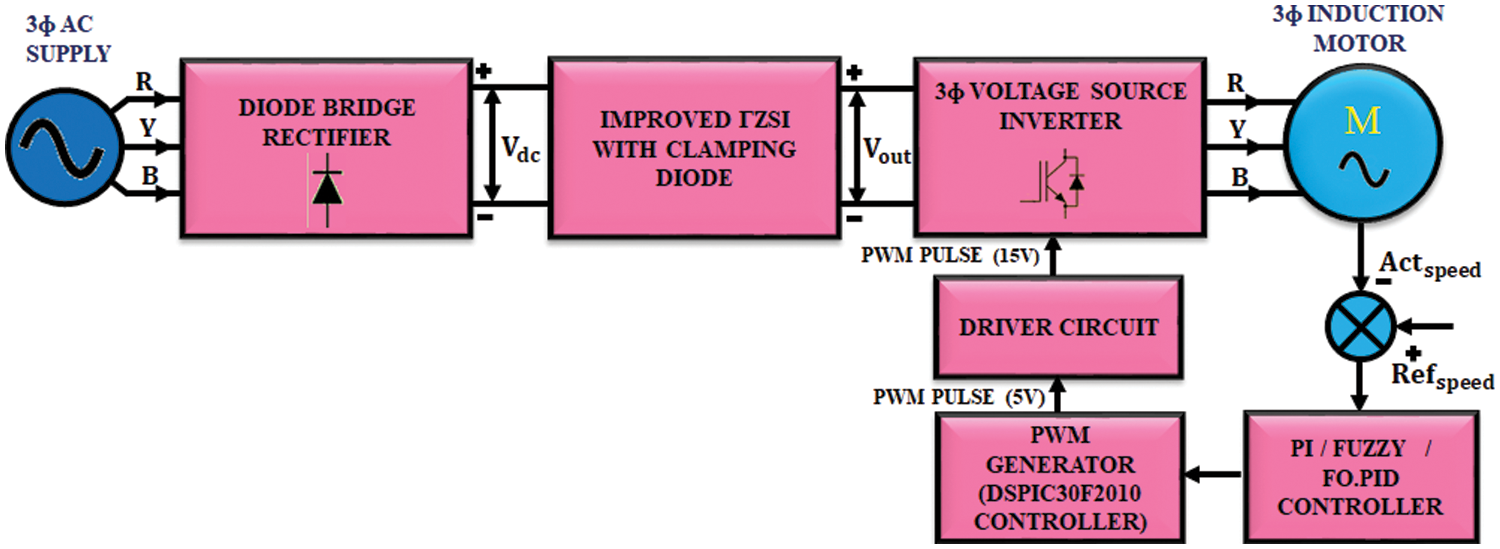
Figure 1: Proposed block diagram
3Φ AC supply is given to the diode bridge rectifier. In 3Ф induction motor, the speed decreases due to load and the ripples get injected. This ripples get increased with the increase in speed. Due to this oscillation, the produced back emf is increased and it affects the source voltage. In order to rectify source voltage problem, diode bridge rectifier is employed, which involves in converting AC to DC. The output of diode bridge rectifier is given to improved ΓZSI, which significantly enhances the low DC voltage and minimizes the ripples in input voltage. The output of ΓZSI is fed to 3Ф induction motor through 3Ф VSI. The improved ΓZSI operates in shoot through mode to prevent short circuit problem. The current when pass through the short circuit side gets charged immediately. Advantages of this inverter are constant input voltage, reduction of ripples and voltage overshoots due to an additional clamping diode and high output voltage.
Basic structure of the proposed inverter is depicted at Fig. 2. An improved ΓZSI uses fewer components to get high voltage gain by using a greater modulation index, which in turn results in lesser shoot-through duty cycle. Additionally, output voltage of improved ΓZSI is tuned within a tapered range of
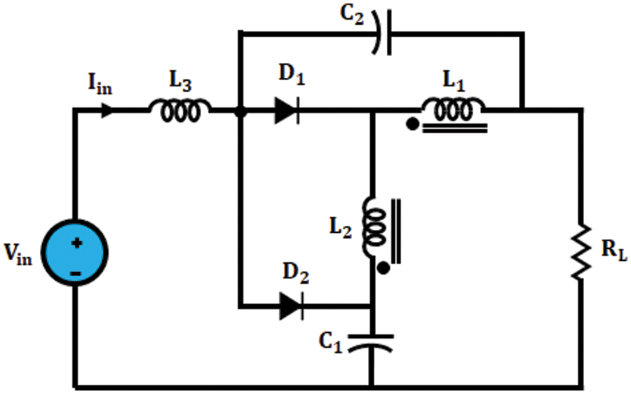
Figure 2: Circuit diagram of improved ΓZSI
An improved ΓZSI boost Factor (B) is expressed as,
Here, D signifies the duty cycle whereas n signifies the coupled inductor’s turns ratio.
Characteristic of improved ΓZSI are given below,
1. In improved ΓZSI, input current is continuous and there is no need for any extra filter.
2. Unlike Trans-ZSI, tZSI and ΓZSI, it delivers startup inrush current suppression since there is no current flow at startup to the major circuit.
3. It has maximum voltage gain. An improved ΓZSI uses lesser shoot through duty cycle with similar input or output states, which in turn results in lesser voltage stress and improved power quality output.
Mode 1: Shoot-through mode
Improved ΓZSI with clamping diodes circuit of mode 1 is depicted in Fig. 3.
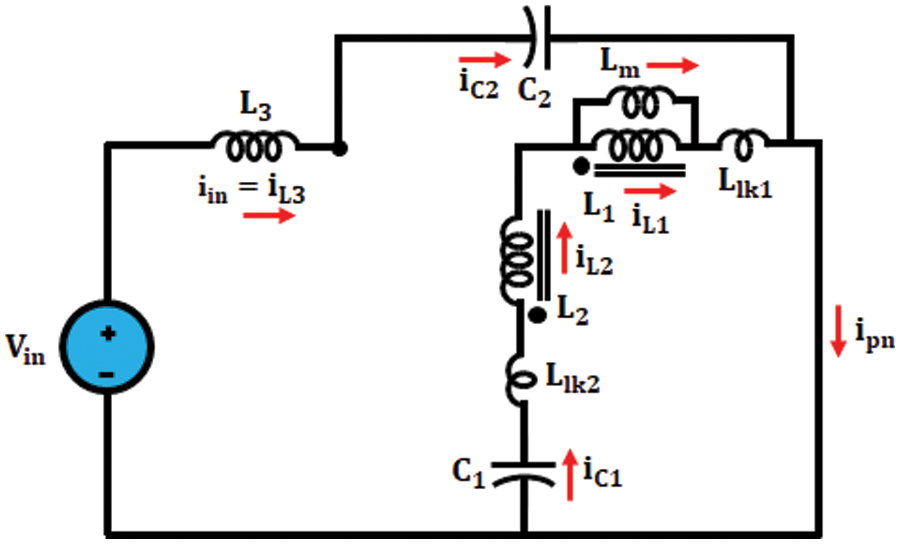
Figure 3: Mode 1
All switches of same legs are switched ON in shoot-through mode and network is similar to short circuit. In this mode, diodes
Mode 2: Non-Shoot-through mode
The circuit of improved ΓZSI in mode 2 is depicted in Fig. 4.
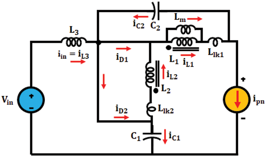
Figure 4: Mode 2
It contains two zero modes as well as six active modes. Diodes
3.1.1 Boost Capacity of Improved ΓZSI
DC-link voltage ratio at bridge inverter is known as boost factor of inverter. A simplified circuits of improved ΓZSI inverter during mode 1 and mode 2 are depicted in Fig. 5.
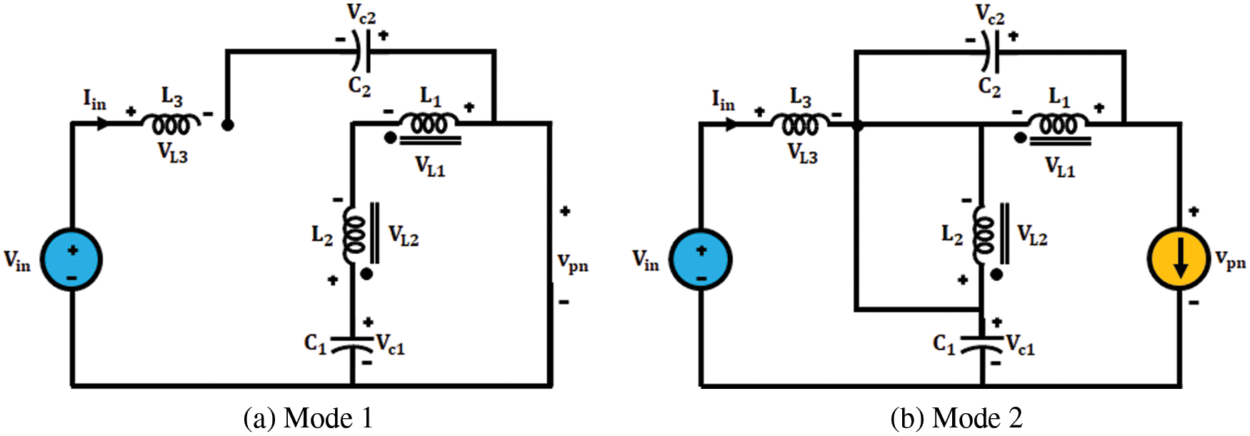
Figure 5: Simplified circuits of improved ΓZSI
Apply KVL in shoot through mode,
Similarly, Apply Kirchhoff’s Voltage Law in non-shoot through mode,
Here, the input voltage is specified as
Substitute (iv) in (i) we get,
Across
Substitute (vi) in (v) we get,
where, n denotes turns ratio,
Improved ΓZSI with clamping diode’s DC-link potential,
Thus, the Boost factor B is represented as,
3.2 Modeling of 3Φ Induction Motor
The potential and torque equations, which characterize dynamic behavior at induction motor aid in explaining the differential equation at trouble-free way. In order to reduce difficulties in solving the equations, a change in variable is employed by neglecting time fluctuating inductances. The circuit diagram of induction motor is significantly highlighted in Fig. 6.
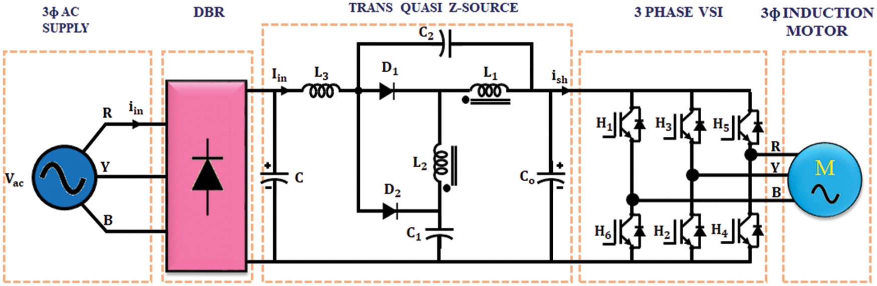
Figure 6: Circuit diagram of an induction motor with improved ΓZSI with clamping diode
3.2.1 Induction Motor Model Generalized Idea in an Arbitrary Reference Frame
Even though real parameters remain sinusoidal, it is beneficial for obtaining device variables like dc quantities. These are accomplished through requiring the reference frame that is same as that of sinusoidal variable at the same angular speed. Instead of calculating every particular reference frame, this is beneficial to maintain common conversion of arbitrary reference frame.
3.2.2 Switching Over from 2Φ to 3Φ
If the uniformity among 3Φ and 2Φ machine is known, it is possible to obtain dynamic model of induction motor. The similarities depend on quantity of magneto motive force created in 2Φ as well as 3Φ windings with uniform current magnitudes. Consider every 3Φ winding as well as 2Φ windings that have
where,
Interconnection between
In direct and Quadrature axes, the above equation is expressed as,
By using forthcoming transformation the prompt value of stator as well as rotor currents are computed and it is expressed as,
3.2.3 Computation of Flux Linkage
The currents are find by substituting the value of flux linkage,
Torque plus speed in rotor are expressed like,
The sum of proportion and integration coefficient is known as PI controller. The schematic representation of PI is depicted in Fig. 7.
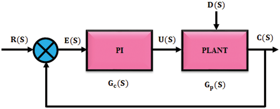
Figure 7: PI controller
At the same control error, proportion coefficient is greater and output power is low. To control proportional integral controller, position integration time is set to zero and proportion time is set to maximum. It attains periodic oscillation of device by gradually lowering the proportionality coefficient. The value received from proportionality coefficient is twice greater than optimal value of integration time. Problems faced by IM with PI controllers are increase in settling time and occurrence of maximum peak overshoot and also takes lot of time to stabilize the speed that aids the working of machine.
3.4 Modeling of Fractional Order PID Controller
On comparing with integer order controller, FOPID controller gives enhanced performance. The block’s schematic representation for FOPID controller is presented in Fig. 8.
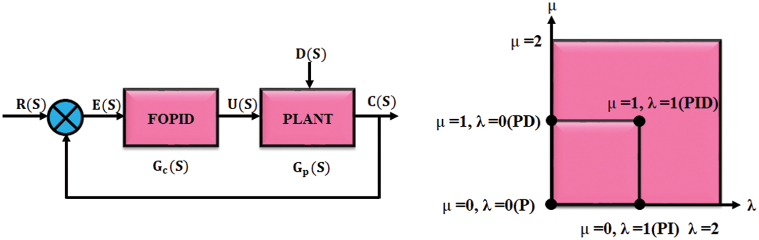
Figure 8: Fractional order PID controller
As a part of control system, it uses fractional order integration. By using fractional calculus, it improves and generalizes well established system and control strategies. Due to their additional degrees of freedom, the fractional order controller is selected. The controller order of fractional satisfies the criterions like sensitivity, specification, removing steady state error.
When comparing fractional order PID controller with conventional PI controller, it gives better performance with good dynamic response.
The generalization of non-integer order of fractional PID controller is expressed as,
Here, the control signal is signified as
3.5 Modeling of GWO-PI Controller
To tune proportional integral controller, the gray wolf optimizer is used. This novel population established algorithm is developed through aging. This technique imitates the social hierarchy as well as hunting performance of grey wolves. In GWO algorithm, four kinds of groups namely
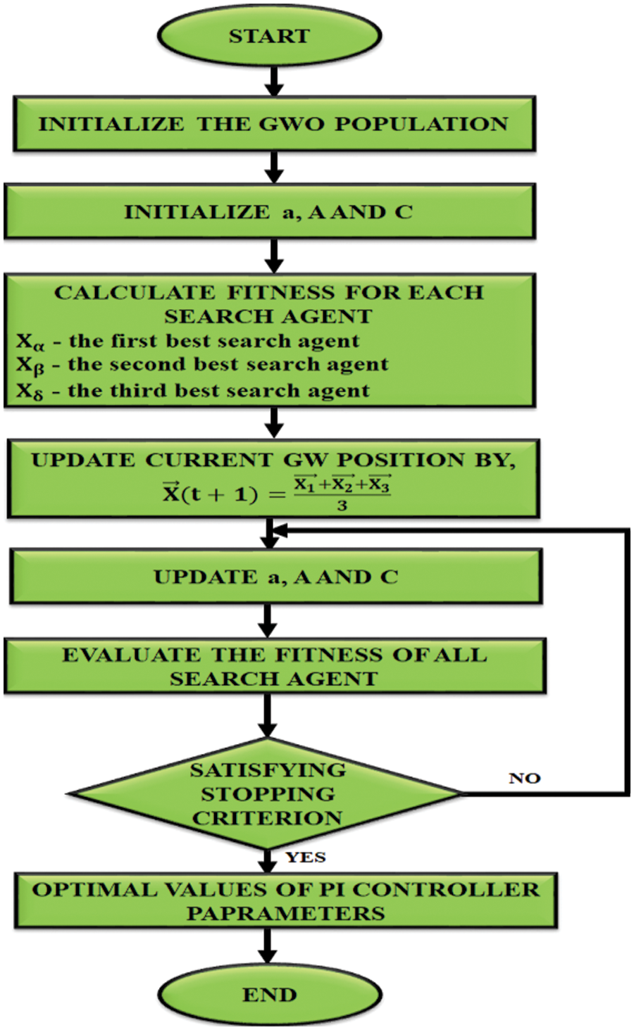
Figure 9: Flow chart for GWO algorithm
A number of parameters are needed in this algorithm in order to be set are,
• Initialize
• Search the search agent’s amount.
• Amount of iterations found is maximum.
• Number of positions chosen as searching the neighborhood and the criteria for stopping.
One of the major steps for grey wolf hunting is given below,
• Tracking, chasing as well as impending prey.
• Pursuing, encircling as well as distressing prey till that ceases to move.
• Violence against prey.
Almost appropriate solution is considered as alpha
where, t denotes current iteration,
where,
So far, the first three finest solutions has been attained and update other search agents to change their locations according to location of finest hunt agents. Thus the given expressions projected is regarded as follows,
Update current GW position is expressed as,
From this, we know that
A source voltage waveform of improved ΓZSI is depicted in Fig. 10. Shape of waveform is sinusoidal in nature. To stabilize load currents, a 3Ф AC voltage waveform shifts 120o with respect to one another. It has the power to boost up input voltage in a wider range.
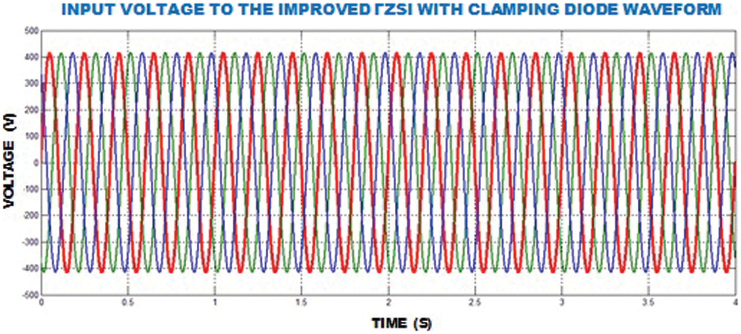
Figure 10: Input voltage of improved ΓZSI waveform
An input potential of improved ΓZSI waveform is depicted in Fig. 11. An input potential of
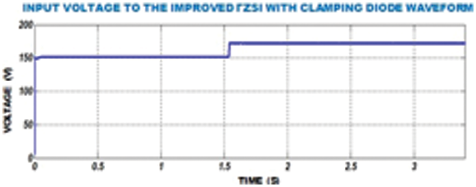
Figure 11: Input voltage of improved ΓZSI with clamping diode waveform
An output potential of improved ΓZSI waveform is depicted in Fig. 12. So this inverter boosts up the output voltage to 6 times with the amplitude of
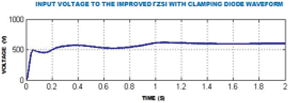
Figure 12: Output voltage of improved ΓZSI with clamping diode waveform
An
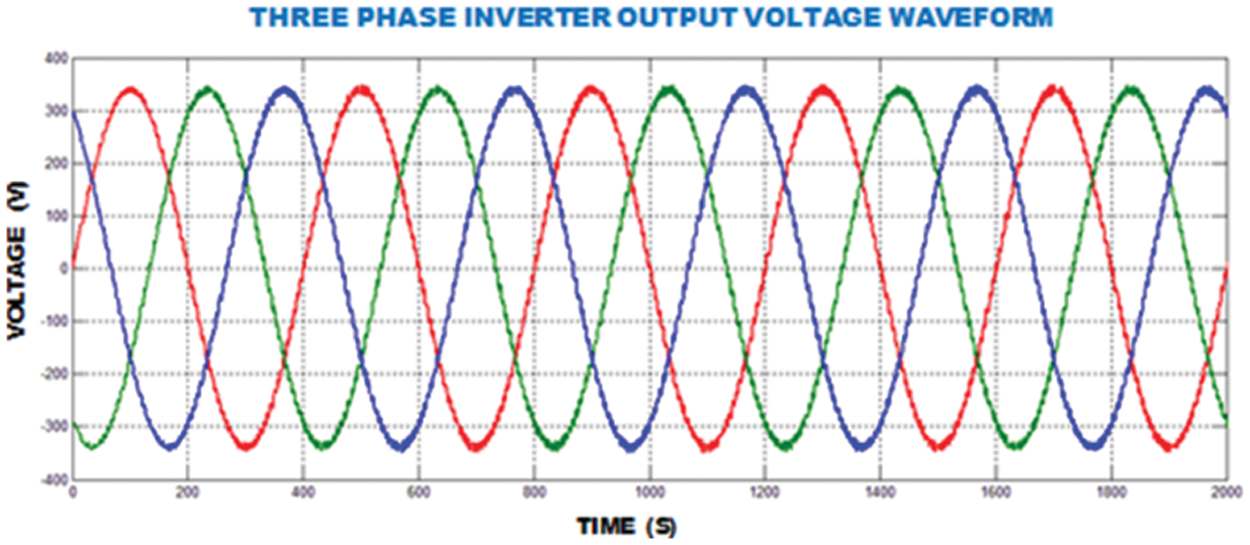
Figure 13:
Speed waveform of IM with proportional integral controller is depicted in Fig. 14. In this graph, we observe that speed attained through PI controller is
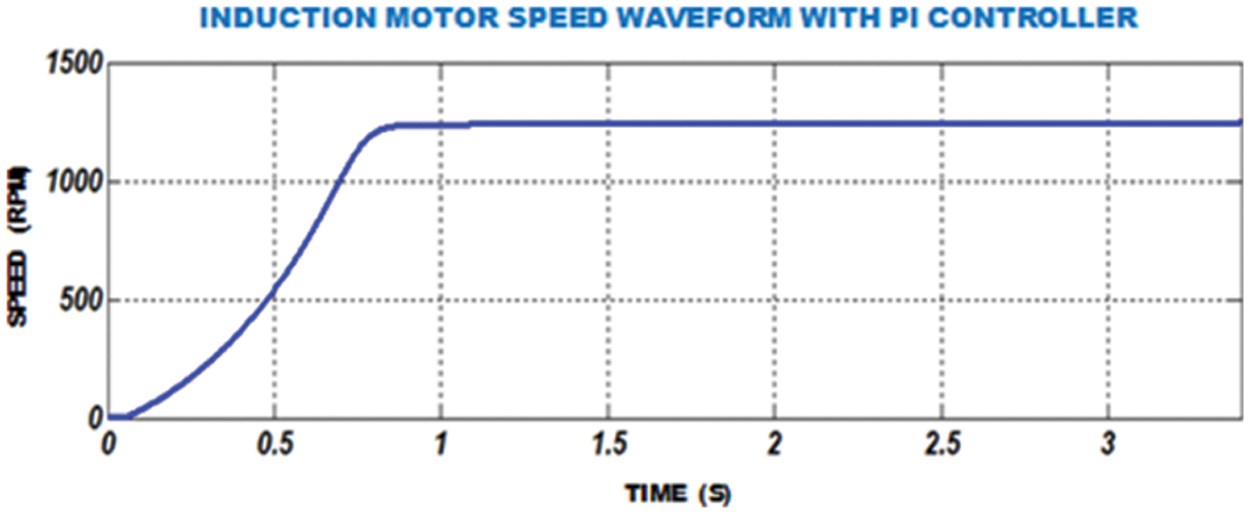
Figure 14: Speed waveform of FOPID-IM
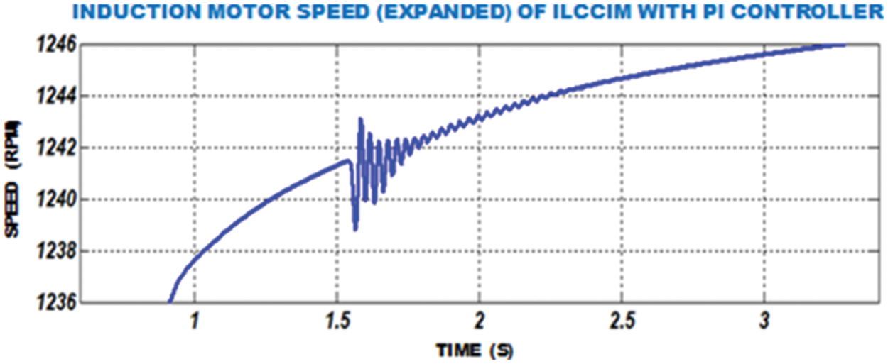
Figure 15: Speed waveform of FOPID-IM
Waveform for Induction motor instant response through FOPID controller is depicted in Fig. 16. In the graph, initially there is an oscillation in speed and then after
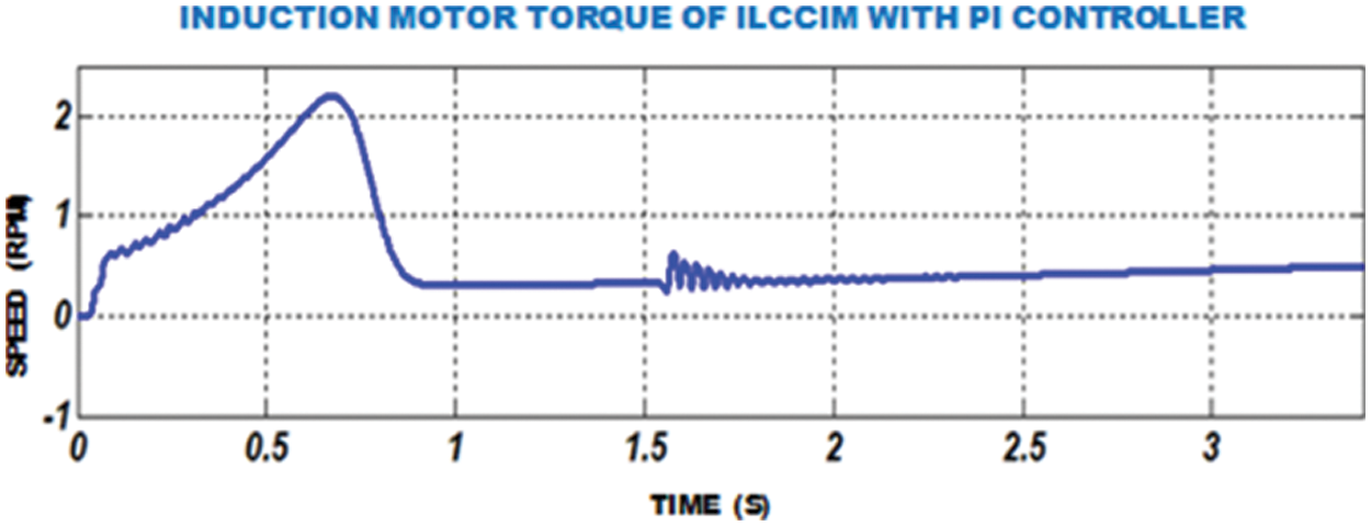
Figure 16: Waveform of IM moment through FOPID
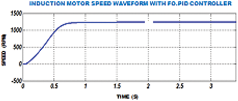
Figure 17: IM speed waveform with fractional order PID controller
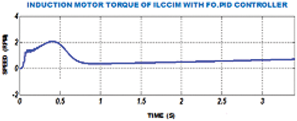
Figure 18: IM torque of ILCCIM with FOPID controller
The waveform of IM speed using GWO-FOPID is depicted in Fig. 19. The waveform of IM torque using GWO-FOPID is depicted in Fig. 20.
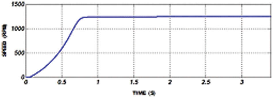
Figure 19: IM speed waveform with GWO-FOPID
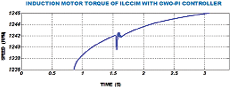
Figure 20: IM torque waveform with GWO-FOPID
The proposed method contains 3
FPGA controller is employed to operate motor at a constant speed and also 3
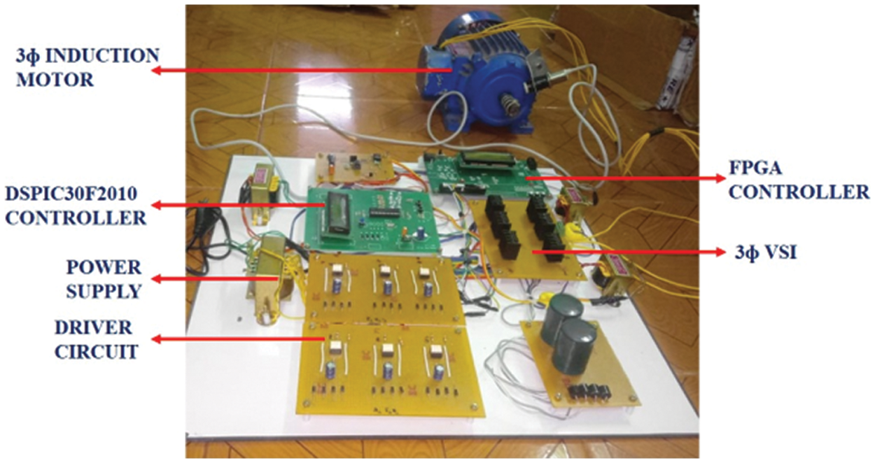
Figure 21: Hardware implementation
Input voltage of improved ΓZSI is depicted at Fig. 23. Output potential is boosted up and retains constant by means of improved ΓZSI. The input voltage is set to
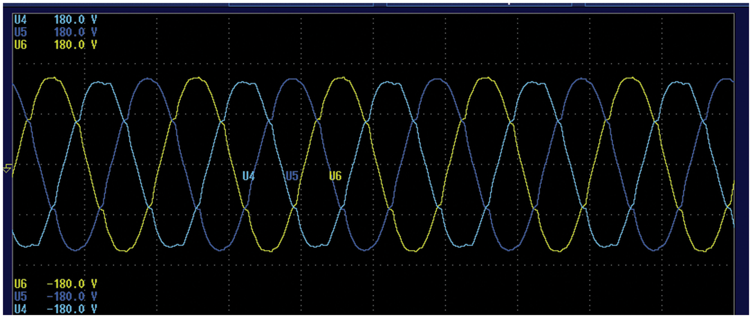
Figure 22: Input 3ϕ AC voltage waveform
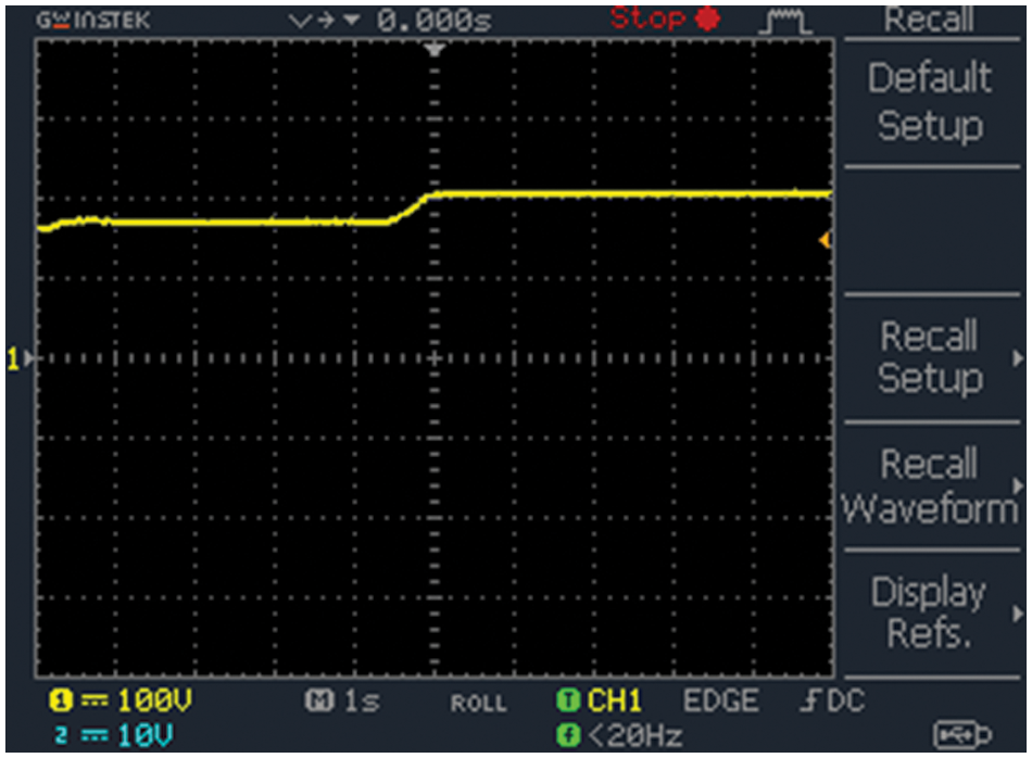
Figure 23: Input voltage of improved ΓZSI
Output potential of the improved ΓZSI is depicted in Fig. 24. It has high modulation index in shoot-through mode in order to achieve voltage gain in improved ΓZSI. As ripples present in voltage are controlled, it also minimizes switching stress.
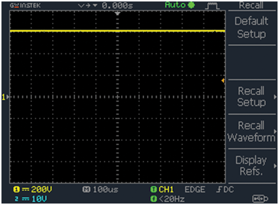
Figure 24: Output voltage of improved ΓZSI
Output voltage of 3Ф VSI is depicted in Fig. 25. A 3Ф VSI is chosen because of high power. This inverter consists of 3 legs with 6 switches. It produces not only 3Ф potential on the other hand the power towards control magnitude, phase as well as frequency. It achieved both in
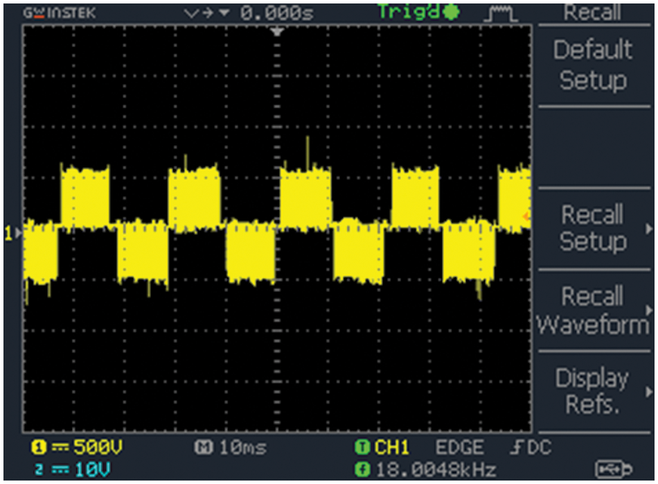
Figure 25: 3Ф VSI output voltage
The VSI output potential with filter is depicted Fig. 26. In order to generate stable AC voltage at output, VSI are commonly applied in continuous power supplies. The reference signals are compared with high frequency carrier waveform in order to obtain control pulses for AC output. The output potential is directly affected due to any changes in output load.
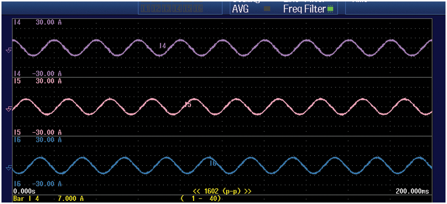
Figure 26: VSI output voltage with filter
Speed waveform with PI, FOPID and GWO-PI is illustrated in Fig. 27. Unlike PI and FOPID, the GWO-FOPDI provides good performance. The PI controller has the ability to reduce steady state error, but this controller response slowly to instant distortion, needs lot of time to settle and oscillations in speed. To overcome these issues, FOPID controller is employed and it succeeds all issues faced by PI controller. FOPID controller maintains stable speed in a robust manner and gives more adjustable time and frequency responses but fails to overcome maximum peak overshoot problem. In order to reduce this problem, GWO is employed to tune the PI controller. From the above speed waveform of PI, FOPID and GWO-FOPID, it is depicted that GWO-FOPDI gives excellent response then provides higher efficiency in stable state and also reduces the settling time.
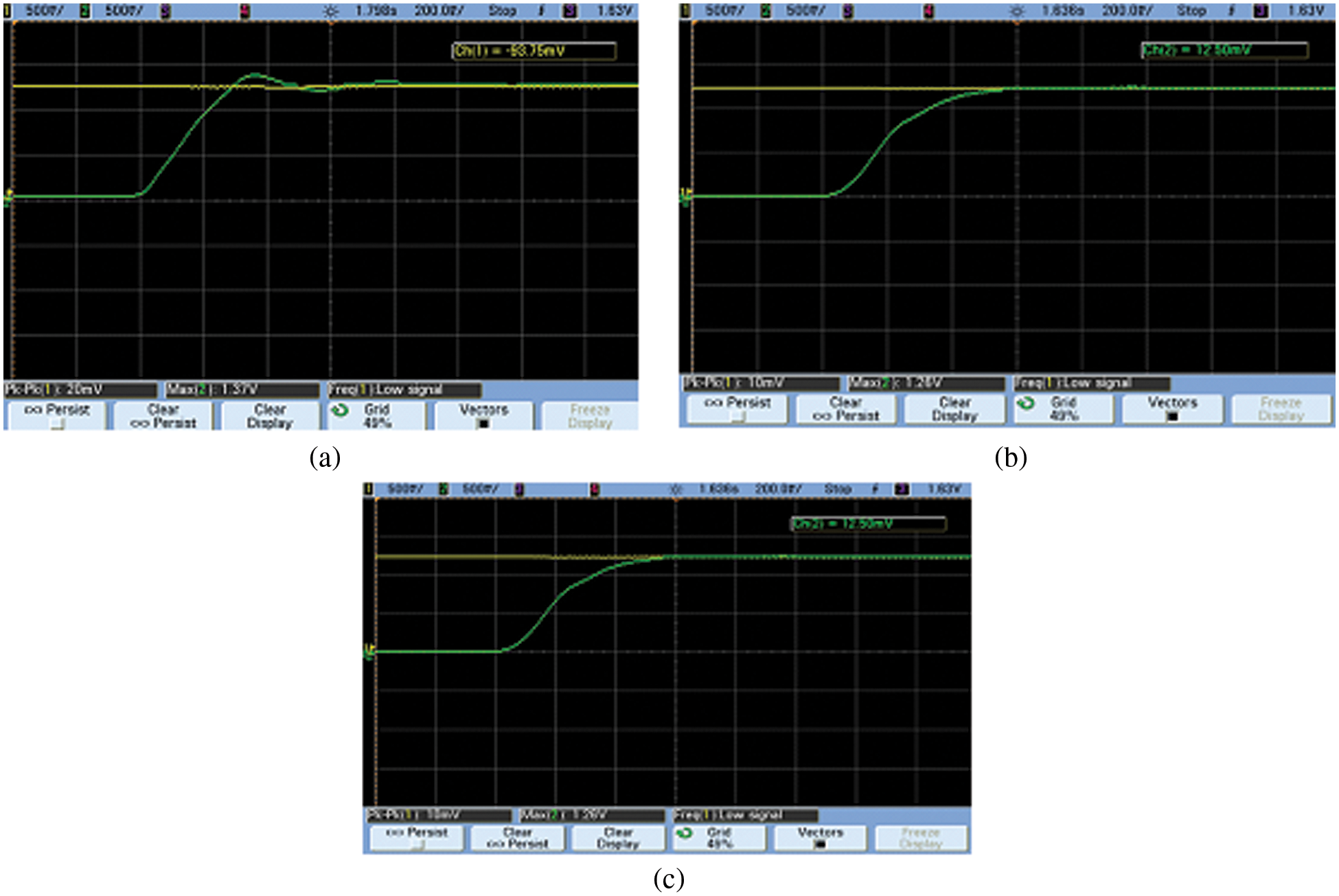
Figure 27: (a) Speed waveform with proportional integral, (b) Speed waveform with FOPID controller, (c) Speed waveform with GWO-FOPID
After analysis of time domain, peak signal amplitude needed by motor is reduced from
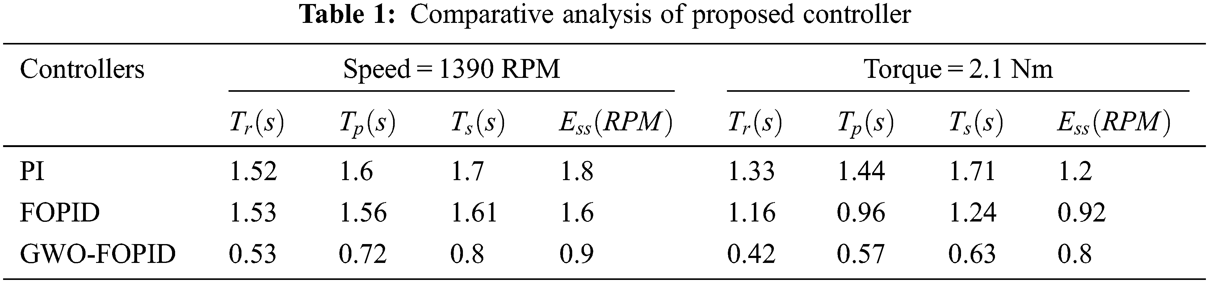
The torque variable with PI controller, FOPID and GWO-FOPID are listed out in Tab. 1. Time needed from signal is reduced from
Motor speed efficiency comparison of PI, FOPID and GWO-FOPID is depicted in Fig. 28. From this comparison, GWO-FOPID depicts higher efficiency.
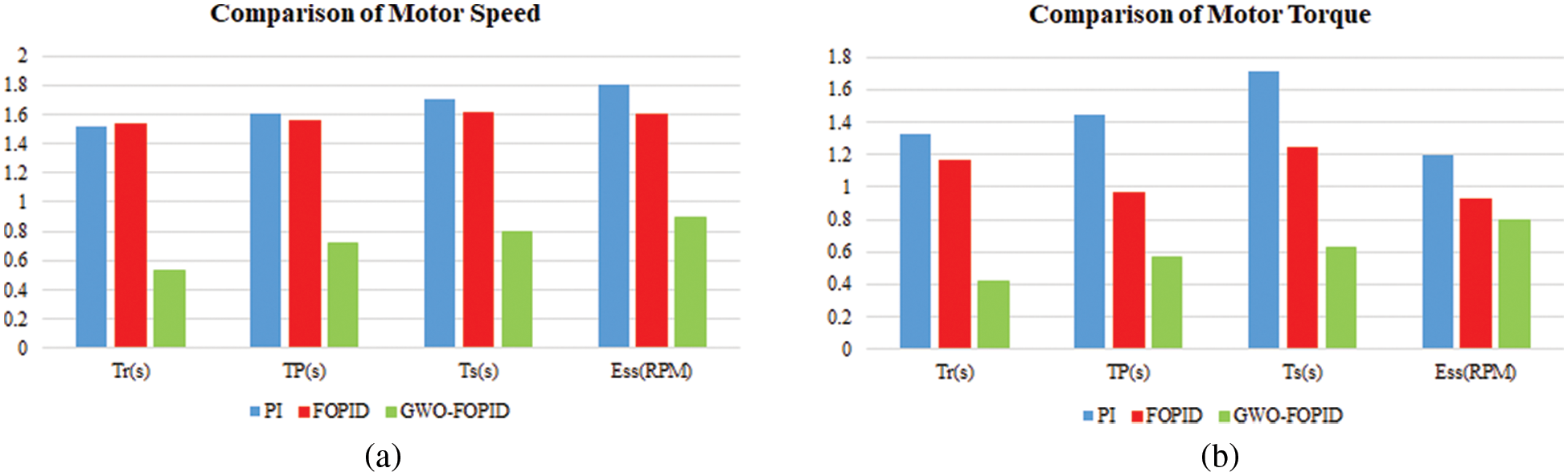
Figure 28: Comparative analysis of (a) speed and (b) torque
The performance of the GWO-PI controller in terms of raise time, peak time, settling time and steady state error is analogized with other existing controllers as highlighted in Tab. 1. The result of this analysis validates that the proposed control approach delivers optimal performance than the others.
An improved ΓZSI with a clamping diode is proposed in this work. To operate the induction motor at rated speed, different controllers are used to control the voltage source inverter. With conventional PI controller, settling time increases and maximum peak overshoot occurs. Additionally, fractional order PID controller and GWO technique that employed in enhancing its enactment of speed control of IM. Fractional order PID control is employed to enhance the performance of PI controller and also provide good speed response as well as steady state error. Moreover, Gray wolf optimization technique is used to optimize maximum peak overshoot problems in PI controller. In accordance with the comparative analysis of motor performance under optimal torque and speed values, it is validated that the speed response of rise time, settling time and peak time have been improved upto 50%, 44% and 36%. The improvement in reduction of steady state speed error and torque error are 40% and 20%. The whole performance is executed in MATLAB simulation.
Funding Statement: The authors received no specific funding for this study.
Conflicts of Interest: The authors declare that they have no conflicts of interest to report regarding the present study.
References
1. J. Talla, V. Q. Leu, V. Smídl and Z. Peroutka, “Adaptive speed control of induction motor drive with inaccurate model,” IEEE Transactions on Industrial Electronics, vol. 65, no. 11, pp. 8532–8542, 2018. [Google Scholar]
2. A. T. Alexandridis, G. C. Konstantopoulos and Q. C. Zhong, “Advanced integrated modeling and analysis for adjustable speed drives of induction motors operating with minimum losses,” IEEE Transactions on Energy Conversion, vol. 30, no. 3, pp. 1237–1246, 2015. [Google Scholar]
3. A. A. Ahmed, B. K. Koh and Y. Lee, “A comparison of finite control set and continuous control set model predictive control schemes for speed control of induction motors,” IEEE Transactions on Industrial Informatics, vol. 14, no. 4, pp. 1334–1346, 2018. [Google Scholar]
4. M. Bodson, “Speed control for doubly fed induction motors with and without current feedback,” IEEE Transactions on Control Systems Technology, vol. 28, no. 3, pp. 898–907, 2020. [Google Scholar]
5. J. Chen, J. Huang and Y. Sun, “Resistances and speed estimation in sensorless induction motor drives using a model with known regressors,” IEEE Transactions on Industrial Electronics, vol. 66, no. 4, pp. 2659–2667, 2019. [Google Scholar]
6. J. Li, H. P. Ren and Y. R. Zhong, “Robust speed control of induction motor drives using first-order auto-disturbance rejection controllers,” IEEE Transactions on Industry Applications, vol. 51, no. 1, pp. 712–720, 2015. [Google Scholar]
7. Y. S. Lim, J. S. Lee and K. B. Lee, “Advanced speed control for a five-leg inverter driving a dual-induction motor system,” IEEE Transactions on Industrial Electronics, vol. 66, no. 1, pp. 707–716, 2019. [Google Scholar]
8. X. Zhu, B. Zhang and D. Qiu, “A high boost active switched quasi-z-source inverter with low input current ripple,” IEEE Transactions on Industrial Informatics, vol. 15, no. 9, pp. 5341–5354, 2019. [Google Scholar]
9. R. Errouissi, A. A. Durra and S. M. Muyeen, “Experimental validation of a novel PI speed controller for AC motor drives with improved transient performances,” IEEE Transactions on Control Systems Technology, vol. 26, no. 4, pp. 1414–1421, 2018. [Google Scholar]
10. F. A. A. Meinagh, J. Yuan and Y. Yang, “Analysis and design of a high voltage-gain quasi-Z-source DC–DC converter,” IET Power Electronics, vol. 13, no. 9, pp. 1837–1847, 2020. [Google Scholar]
11. Y. Zhou, H. Li and H. Li, “A single-phase PV quasi-z-source inverter with reduced capacitance using modified modulation and double-frequency ripple suppression control,” IEEE Transactions on Power Electronics, vol. 31, no. 3, pp. 2166–2173, 2016. [Google Scholar]
12. D. S. Vidhya and T. Venkatesan, “Quasi-z-source indirect matrix converter fed induction motor drive for flow control of dye in paper mill,” IEEE Transactions on Power Electronics, vol. 33, no. 2, pp. 1476–1486, 2018. [Google Scholar]
13. M. Mohamadi, A. Rashidi, S. M. S. Nejad and M. Ebrahimi, “A switched reluctance motor drive based on quasi z-source converter with voltage regulation and power factor correction,” IEEE Transactions on Industrial Electronics, vol. 65, no. 10, pp. 8330–8339, 2018. [Google Scholar]
14. Z. Liang, S. Hu and X. He, “Analysis and suppression strategy for the double-line frequency pulsation in single-phase quasi-z-source converter,” IEEE Transactions on Power Electronics, vol. 34, no. 12, pp. 12567–12576, 2019. [Google Scholar]
15. N. Farah, Md. H. N. Talib, N. S. M. Shah, Q. Abdullah, Z. Ibrahim et al., “A novel self-tuning fuzzy logic controller based induction motor drive system: An experimental approach,” IEEE Access, vol. 7, pp. 68172–68184, 2019. [Google Scholar]
16. M. S. Zaky and M. K. Metwaly, “A performance investigation of a four-switch three-phase inverter-fed IM drives at low speeds using fuzzy logic and PI controllers,” IEEE Transactions on Power Electronics, vol. 32, no. 5, pp. 3741–3753, 2017. [Google Scholar]
17. Q. A. Tarbosh, O. Aydogdu, N. Farah, M. N. Talib, A. Salh et al., “Review and investigation of simplified rules fuzzy logic speed controller of high performance induction motor drives,” IEEE Access, vol. 8, pp. 49377–49394, 2020. [Google Scholar]
18. B. S. Umesh and K. Sivakumar, “Multilevel inverter scheme for performance improvement of pole-phase-modulated multiphase induction motor drive,” IEEE Transactions on Industrial Electronics, vol. 63, no. 4, pp. 2036–2043, 2016. [Google Scholar]
19. D. Ramasubramanian and V. Vittal, “Positive sequence induction motor speed control drive model for time-domain simulations,” IET Generation, Transmission & Distribution, vol. 11, no. 7, pp. 1809–1819, 2017. [Google Scholar]
20. Y. Han, J. Yu, L. Zhao, H. Yu and C. Lin, “Finite-time adaptive fuzzy control for induction motors with input saturation based on command filtering,” IET Control Theory & Applications, vol. 12, no. 15, pp. 2148–2155, 2018. [Google Scholar]
21. X. R. Zhang, W. F. Zhang, W. Sun, X. M. Sun and S. K. Jha, “A robust 3-D medical watermarking based on wavelet transform for data protection,” Computer Systems Science & Engineering, vol. 41, no. 3, pp. 1043–1056, 2022. [Google Scholar]
22. X. R. Zhang, X. Sun, X. M. Sun, W. Sun and S. K. Jha, “Robust reversible audio watermarking scheme for telemedicine and privacy protection,” Computers, Materials & Continua, vol. 71, no. 2, pp. 3035–3050, 2022. [Google Scholar]
Cite This Article
 Copyright © 2023 The Author(s). Published by Tech Science Press.
This work is licensed under a Creative Commons Attribution 4.0 International License , which permits unrestricted use, distribution, and reproduction in any medium, provided the original work is properly cited.
 Downloads
 Citation Tools