
 Submit a Paper
 Propose a Special lssue
 Open Access
ARTICLE
Optimized PI Controller Based Reboost Luo Converter for Micro Grid Application
1 Marthandam College of Engineering and Technology, Kuttakuzhi, 629177, India
2 KSR College of Engineering, Thiruchengode, 637215, India
* Corresponding Author: R. K. Negesh. Email:
Intelligent Automation & Soft Computing 2023, 36(1), 1151-1172. https://doi.org/10.32604/iasc.2023.027764
Received 26 January 2022; Accepted 14 June 2022; Issue published 29 September 2022
 View Full Text
 Download PDF
Abstract
In the recent era, the significance of Renewable Energy (RE) sources in the process of power generation has attained considerable attention as it provides multiple beneficial impacts without harming the environment. The Photovoltaic (PV) and Doubly-Fed Induction Generator (DFIG) fed wind turbine are employed as hybrid power sources in this study. The output voltages of these sources are independently controlled by separate controllers in an optimal manner for effectively maximizing the overall performance of the system. The Reboost Luo converter is introduced in this work to maximize the output voltage of PV in an efficient manner whereas the Grey Wolf Optimization (GWO) tuned Proportional Integral (PI) is used to optimize the converter output. The wind turbine output is fed to rectifier that is controlled by a PI controller. Furthermore, a battery setup is utilized with bidirectional converter as a secondary power source to ensure continuous power supply to the grid. An intelligent Adaptive Neuro-Fuzzy Inference System (ANFIS) is implemented to regulate the power flow in two directions between the battery and Point of Common Coupling (PCC). The output of PV, Wind and Battery are combined at a single point and fed to the grid through a three phase inverter. The overall setup is validated through MATLAB Simulink and the performances are verified with the developed experimental prototype.Keywords
The necessity of electricity is extremely high in the day to day life of the people as it aids in almost all the essential deeds of the people by eliminating the labor and manual efforts in an efficient manner. The shortage of power supply is one of the serious issues in the current era, which results in affecting the livelihood of the people in a wider range. Because of this shortage in power supply, several remote areas are facing planned and unplanned power cuts, which makes the people suffer to fulfil the regular electrical demands. Taking this as a serious issue, various researches are carried out to provide uninterrupted power supply to all places including the remote areas.
Recently, many developing countries are moving towards the production of green energy by using non-conventional energy sources to overcome the shortage of power generation [1]. Because of the emergence of multiple industrial sectors and developments in modernization, the power demand is rapidly increased in the recent scenario. For instance, the total consumption of power over a year is recorded as 1372TWh (2018–2019) [2–5]. For many years, people are depending only on the conventional energy sources for generating the power but as the need of electricity is growing linearly [6], it is highly impossible to meet the power demand only by the conventional energy sources. Hence, the Renewable Energy (RE) sources like solar, wind, tidal, ocean, geothermal energies are preferred in the process of power generation. The huge industrial demand of electricity is met by the locally available renewable sources, which involves in lessening the pollution factors in an optimal way [7]. Instead of using the RE sources separately, the combination of two or more RE sources is preferred for maximizing the efficiency of power generation and to afford unremitting power supply to the customer [8,9]. The design and control method of these hybrid sources play a vital role in achieving the expected output [10–13].
It is vital to control the PV and wind systems. Generally, the outcome of PV is a low voltage Direct Current (DC) and it is necessary to convert it to high voltage by using a DC-DC converters. The boost converters are the frequently used converters for boosting the PV voltage but these converters are only applicable for low power applications. Moreover, the cascaded control is necessary for this converter to control the PV voltage [14,15]. In [16], Model Predictive Control (MPC) is adopted for controlling the boost converter and the parametric uncertainty of this converter is rectified with the continuous time MPC through the disturbance observer. The PV Module-Integrated Converter (MIC) is implemented for regulating the PV voltage but the linear cascaded controller is required for controlling converter [17]. Dual mode CUK converter is presented in [18] that works both in continuous and discontinuous conduction modes. In the operation of this converter, the Repetitive Controller (RC) is executed with multiple phase-lead compensator. The PV voltage is assessed by a voltage-divider circuit with a variable scaling factor for SEPIC converter [19]. A combined version of CUK and SEPIC converters for PV systems is discussed in [20], which produces dual output with an added advantage of leakage current elimination. Some of the disadvantages of the above discussed converters are listed in the following lines. The boost converter is highly sensitive to the changes in the duty cycle and it is not possible to attain high-gain by buck-boost converters. However, the SEPIC converters produces the oscillating output current. To overcome these demerits, the REBOOST Luo converter is suggested for in this paper. This converter is preferred in this work mainly for having the advantage of constant input current. As the outcome of PV has chiefly depended on the irradiation, it is highly necessary for tracking the maximum power irrespective of the fluctuating climate conditions. Some of the Maximum Power Point Tracking (MPPT) methodologies for PV systems are discussed as follows. The Perturbation and Observation (P&O) approach is presented in [21], which efficiently tacks the MPP but fails to provide optimal outcomes. The major limitation of P&O approach is that it leads to wastage of energy as it fluctuates around the MPP. The Fractional–order fuzzy logic (FL) based MPPT is presented in [22], which remarkably aids in tracking the MPP irrespective of the temperature oscillations. The MPPT is attained by the adaptive FL that provides faster convergence and accurate outcomes [23]. The Fuzzy is one of the intelligent based MPPT, which performs well in tracking the maximum power. However, it requires more data, which limits the application of this method. Hence, the intelligent based approaches are replaced with the optimization based techniques. Among different optimization techniques, Particle Swarm Optimization (PSO) is the simplest algorithm to track MPPT [24,25]. One of the drawback of PSO is that the required search space is too large. Thus, the GWO algorithm is adopted in this work as it requires less number of search parameters and delivers high performance with optimal results. This present work includes the subsequent processes.
1) The grid tied wind-PV hybrid system is analyzed with the help of individual voltage source converters and battery for ensuring the continuous transfer of power to the grid.
2) MPPTs for wind and PV generators are individually performed by using the pulse width modulated rectifier and GWO-PI controller based REBOOST converter respectively.
3) The stability of the system is analyzed by using the state space model in grid connected mode.
4) Both the simulation and hardware design are done to verify the results in time-domain.
The hybrid micro grid system consists of primary and secondary sources, among which the arrangement of PV and wind generator is considered as the primary source whereas the battery setup is considered as the secondary source. The Reboost Luo Converter and 3Φ sinusoidal carrier based pulse width modulated rectifier are used to track the maximum energy from PV and wind system. The bidirectional buck-boost converter links the battery arrangements with the PCC for lessening the discontinuous property of renewable energy sources and offering local grid support when the renewable energy source are not available. An adaptable and cost effectual interfacing is thus perceived by utilizing the greatly obtainable dc transmission system. The PCC is set at a reference voltage of 600 V. The block representation of the proposed microgrid system is significantly portrayed in Fig. 1.

Figure 1: Block representation of proposed micro grid system
The circuit diagram of the proposed methodology is significantly provided in Fig. 2, which represents the functioning measures of the overall system in an efficient manner.

Figure 2: Circuit diagram of proposed system
The low DC output of PV is fed to the proposed converter and the converter maximizes the PV output in a wider range. The obtained actual voltage of the converter is analogized with the reference voltage and the obtained error is then fed to the GWO tuned PI controller. By using GWO algorithm, the PI controller parameters are efficiently tuned. The PI controller’s output is then given to the Pulse Width Modulation (PWM) generator that generates the necessary pulses for the converter to optimize the converter output in an optimal manner and this optimized output is given to the 3Φ grid through a 3Φ Voltage Source Inverter (VSI). The 3Φ supply is given to the stationary part of DFIG, which links the wind turbine with the power network whereas the rotating part of the DFIG is coupled to the 3Φ PWM rectifier. At the secondary side, the energy from solar and wind is also saved in batteries. With the assistance of the bidirectional converter, the battery receives the energy from both the renewable sources and from the grid at the PCC. The charging and discharging of battery is regulated with the aid of ANFIS by managing the power flow direction from the battery to the inverter. Eventually, the voltage at the PCC is converted into ac by means of the inverter and then fed the utility power line, in which the power synchronization is performed by dq theory. The hysteresis controller, which is located at the grid side generates the necessary PWM pulses for the inverter.
Solar PV generation is one of the RE sources, which gives the advantages like no fuel requirement, no pollution, less maintenance and noise free operation. The subsequent expression relates the voltage–current of PV panel as,
where,
Several types of irradiations have showed the output attributes of a PV panel as non-linear and depended on irradiation level and temperature. The performance of PV array is evidently portrayed through the curves in Fig. 3.
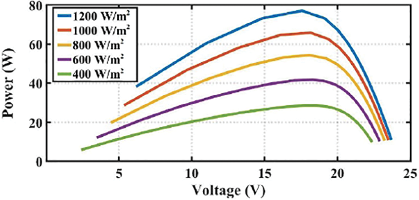
Figure 3: Performance of PV array at T = 250C
It is the combination of Fly back and elementary super lift converters, which has the circuit of one step up isolation transformer, four diodes and four capacitors. The Reboost Luo Converter has the capability of working in both buck and boost mode to raise or reduce the output voltage by tracking the optimal energy point from the solar panel. In addition, it is highly capable of delivering constant input current operation. Fig. 4 illustrates the circuit representation of Reboost Luo Converter.
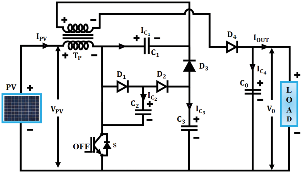
Figure 4: PV fed REBOOST LUO Converter
The subsequent equation expresses the output voltage of the converter as,
Here,
The input current is calculated as,
Thus,
Through these equations, the model of Reboost Luo converter is efficiently derived.
The working modes of this converter is significantly explained in Fig. 5 in an efficient manner.
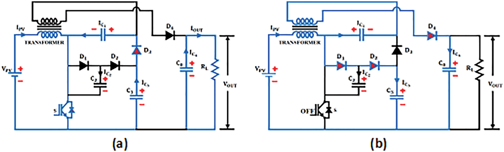
Figure 5: (a) Mode 1 (b) Mode 2
Mode 1
In this mode, the switch S is turned on, in which the current gets flowed through the primary winding of the transformer and the secondary winding is not get conducted. The diode
Mode 2
Switch S is turned off in this state and the input current is made constant as the current flow direction through the primary winding in mode 1 is not changed but remains in the same direction for mode 2. The capacitor C1 that gets charged from the previous operation is added to the charge of primary inductors and flows through the secondary winding of the transformer to charge the output capacitor
The meta-heuristic GWO algorithm emulates the grey wolves’ social manners including searching, following and hunting. The wolves have settled in a group of 5–12 members. In this group, the leader that gives orders to others in hunting the prey is categorized as alpha (α) and the next significant member, who involves in the decision making process is categorized as beta (β). The left over less significant members are categorized as δ and ω. The flowchart of this GWO is significantly provided in Fig. 6.
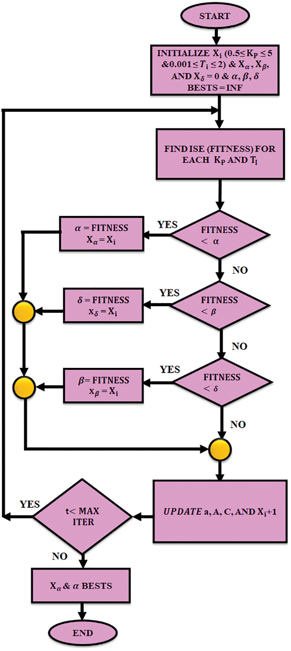
Figure 6: Flowchart of GWO
The hunting process of grey wolves is listed out as finding the prey, encircling the prey, pursuing and attacking the prey.
Here,
where
The iteration is repeated on the basis of the random values. The process of finding the prey location (exploration) is acquired by spreading the search for |A| > 1. The process of attaining the food (exploitation) is acquired by converging the search entities for |A| < 1. The chasing is monitored by α unit whereas it is maintained by β and δ units. The GWO algorithm is introduced to hold in a local lowest but the values A and C help the optimal algorithm to avoid stagnation.
The wind system consists of a turbine, a DFIG, AC/DC rectifier and PI controller as illustrated in Fig. 7. The output electrical energy of the wind is expressed as,
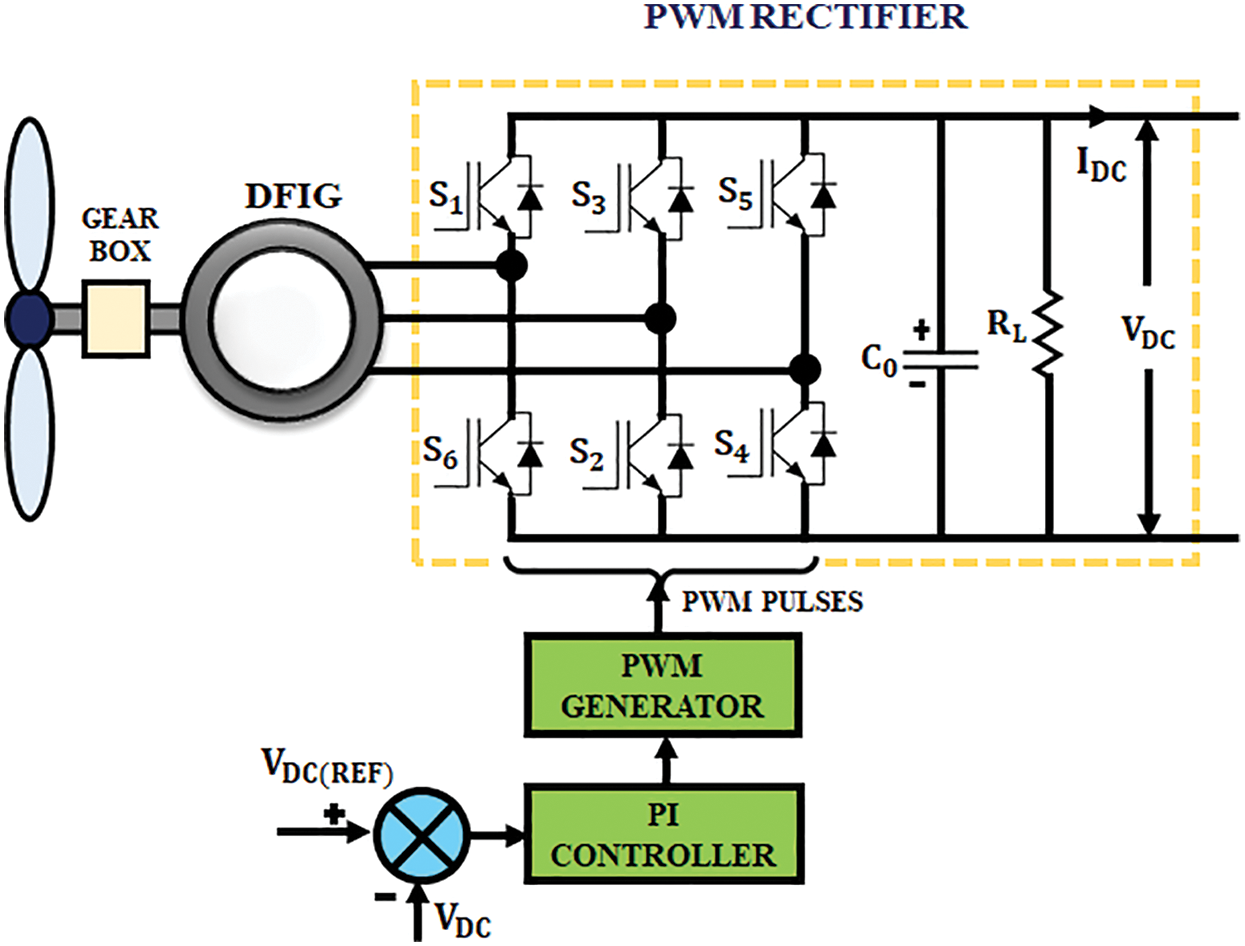
Figure 7: Wind power control system
Here,
The adjustable speed of wind system is used in this method. The turbine output is highly depended on the wind speed. The speed is transformed to dc voltage by using rectifier and then given to the PCC.
The constants Kp and Ki of conventional PI controller are tuned by GWO and the error voltage e(t) is reduced to give improved performance. The output u(t) of PI is expressed as,
The relevant method for reducing the error-integrating scheme is Integral Time Absolute Error (ITAE). It consists of several errors like Integral Square Error (ISE), Integral Time Squared Error (ITSE) and Integral Absolute Error (IAE). The IAE is used for this operation. The mathematical performance index of IAE is expressed as,
where, t stands for time duration of error calculation, e(t) stands for differentiation among the reference, Vref and VDC are the voltages of Reboost Luo converter. The IAE shows the error parameter corresponding to the time. The gains Kp and Ki are adjusted by means of GWO. By adjusting
The cell uses a bidirectional converter to retain the dc-link voltage at the optimal value of 600 V in the power line. The low voltage batteries have raised the life span and enhance the consistency by removing the issues like balancing of battery voltage in large energy system. If the PCC voltage of the RE sources is under the terminal voltage of cell, the converter gets operated in boost mode to direct the power from cells to PCC as shown in Fig. 8.
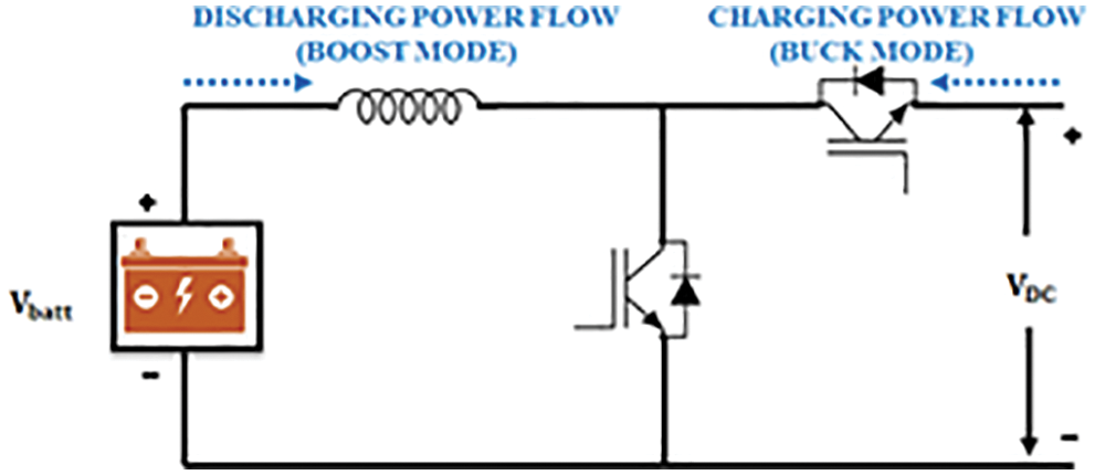
Figure 8: Bidirectional power flow of battery
If the PCC voltage is larger than the terminal voltage of cell, the converter gets operated in buck mode and the energy flows from the PCC to battery for charging the cell. The ANFIS controller generates the pulses of the converter and the sematic representation of this controller is effectively provided in Fig. 9.
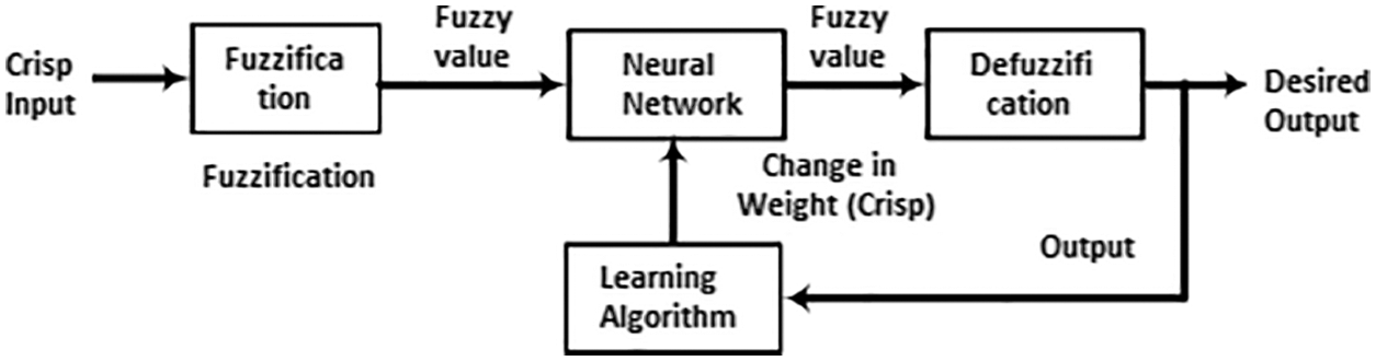
Figure 9: ANFIS based control of converter
Initially, the duty cycle of the bidirectional converter is set at 0.5 and the converter operation is stopped as it fails to increase or decrease its input voltage. Therefore the cells are neither charged nor discharged. Depending upon the variation between the magnitude of PCC voltage level and Battery’s expected voltage level, the ANFIS controller involves in regulating the duty cycle of the converter.
2.6 DQ Based Control OF 3Φ Inverter
The network organization is obtained by allowing the phases of network voltage and inverter output voltage. The network voltage filtering is applied in dq and αβ reference is framed without using the type of network organization. The process of controlling VSI using dq theory is represented in Fig. 10.
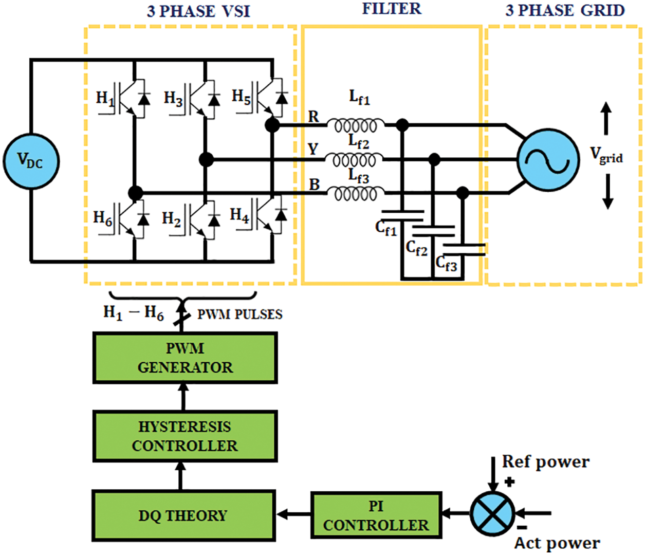
Figure 10: DQ theory based 3ϕ VSI Control
At first, the 3Φ abc quantities are converted into 2Φ αβ stationary reference frames and then converted to dq reference frame that revolves at synchronous velocity.
Among the available control schemes that control the real and imaginary powers of 3Φ inverter linked with direct power line, an accurate method called “Park’s transformation” that utilizes small signal model is utilized in this paper to convert the 3Φ scheme into dq frame (rotating reference). The 3ϕ frame gets transformed into 2ϕ stationary frame as represented in Fig. 11. In addition, the relation between the rotating and stationary frames is remarkably illustrated in Fig. 12.
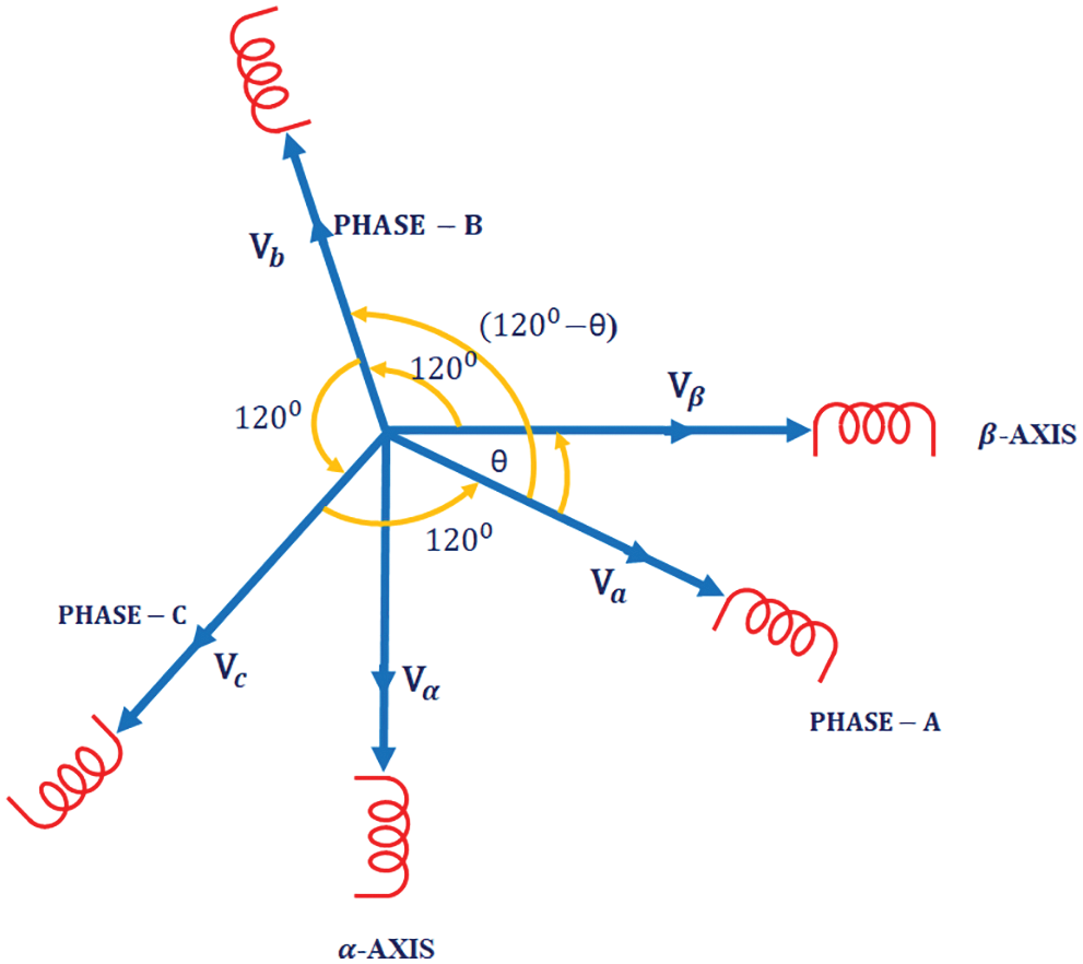
Figure 11: Conversion of 3ϕ frame to 2ϕ stationary frame
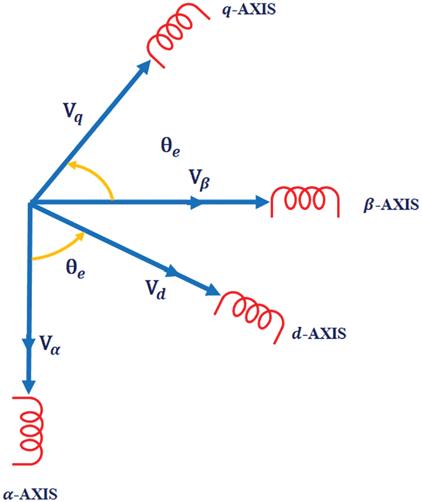
Figure 12: Relation between rotating and stationary frame
The 3Φ command pulse controller gives 3Φ pulse signals by means of three filters. The Clarke transformation is used in 3Φ system to minimize the three-phase elements into the 2Φ stationary reference frame elements. The final two elements have played a primary role in producing the PWM pulses.
The following expression constitutes the Park transformation by which the stationary frame is transformed into rotating frame.
Therefore, the Clarke transformation transforms 3Φ into 2Φ stationary reference frame and Park transformation transforms 2Φ stationary frame to rotating frame. This method creates an imaginable infer dc control loop to successfully track the ac quantities with least amount of steady state error.
A time-domain simulation output is obtained for the proposed hybrid model in Matlab Simulink to estimate and corroborate the performance of the scheme. Fig. 13 significantly illustrates the PV parameters.
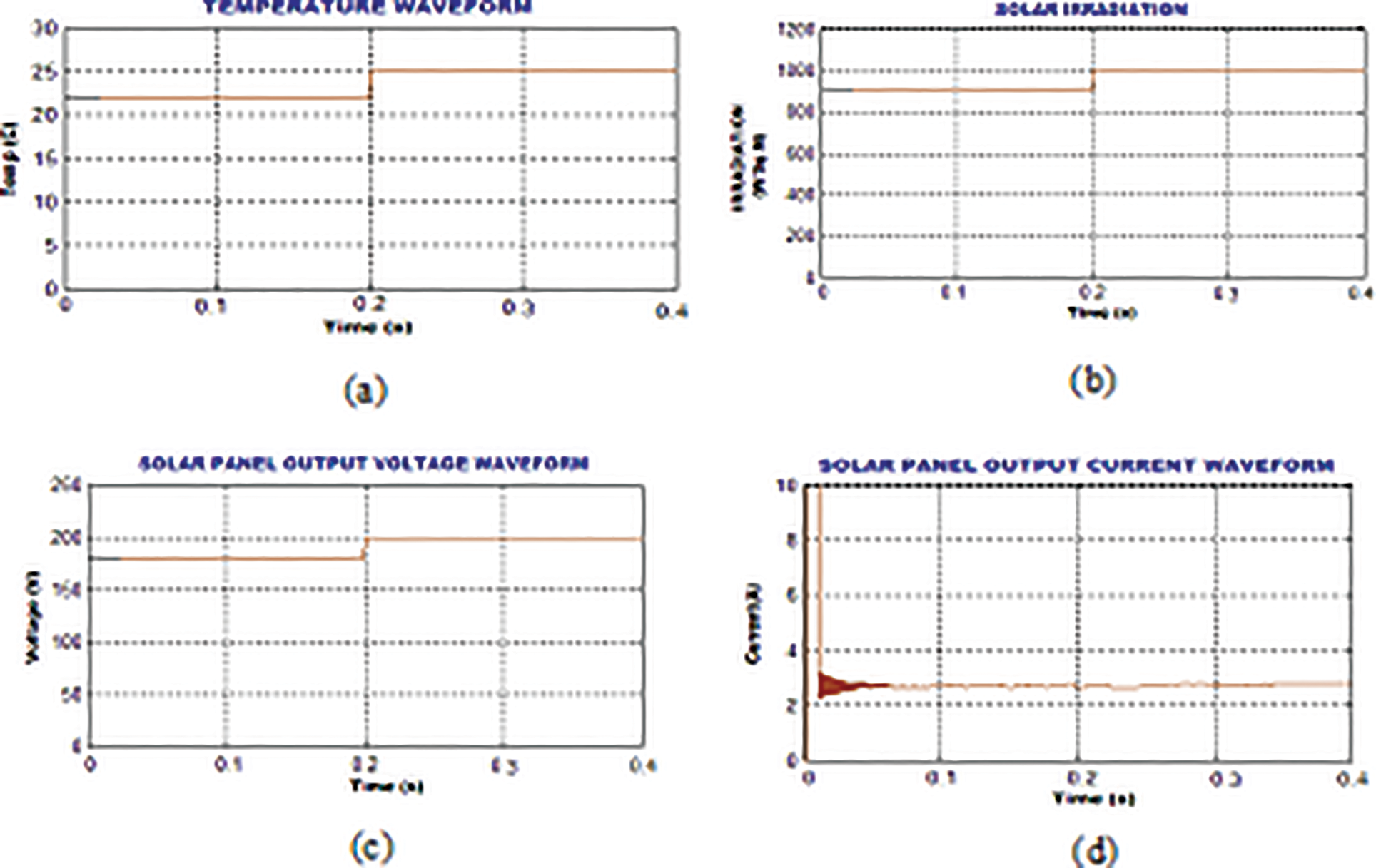
Figure 13: Solar parameters
A 1KW power is selected as maximum power capacity of the solar and wind system. The whole system is built by means of a sim power-system toolbox. A sampling period of 20 ms is applied to discrete simulation. Upon various operating systems, the hybrid system is modelled to offer maximum energy to the grid. The waveforms of converter output, battery voltage and State of Charge (SOC) of Battery are evidently provided in Figs. 14a–14c.
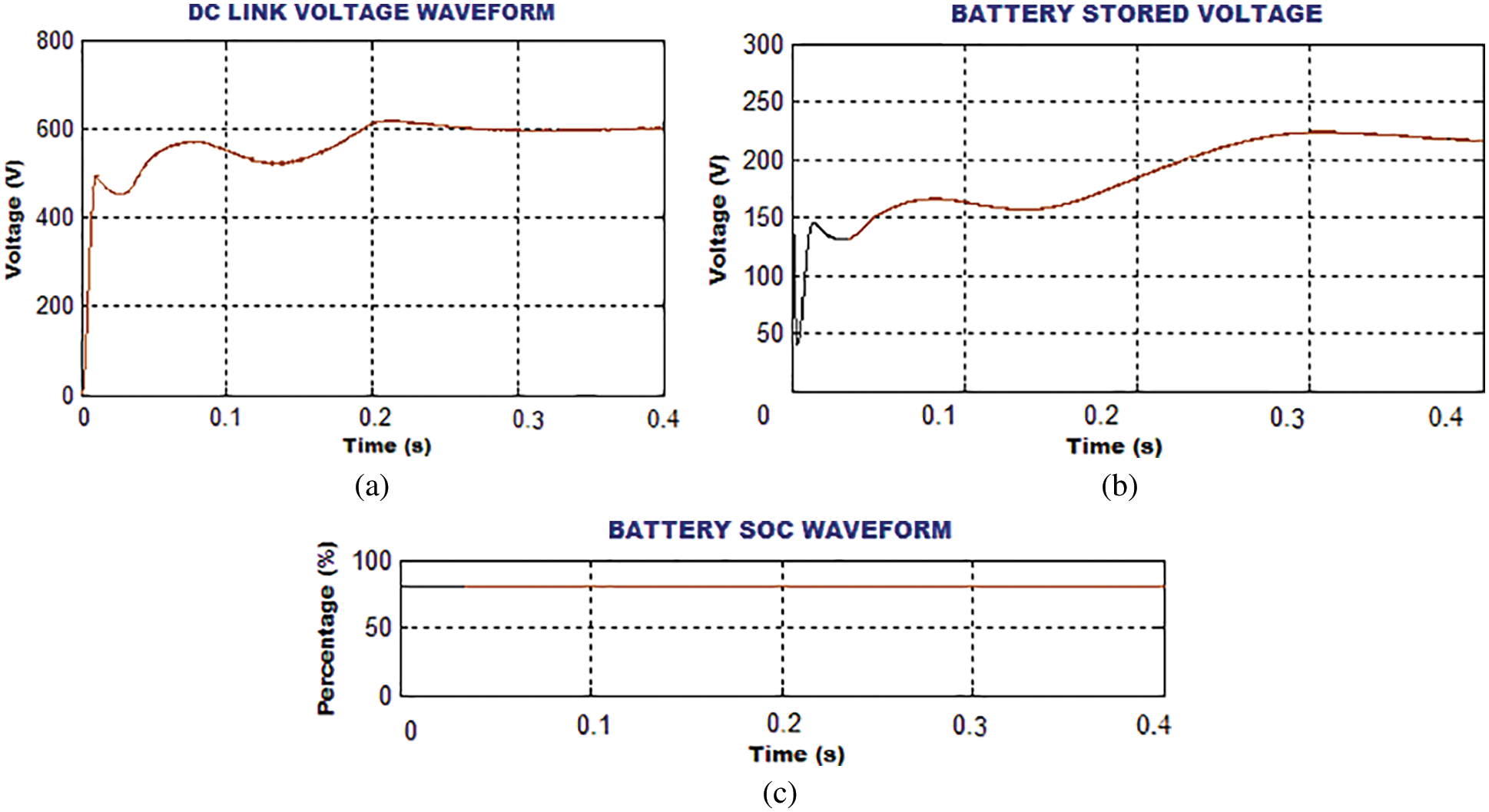
Figure 14: (a) Reboost luo converter output (b) Battery voltage (c) SOC of Battery
As the PV irradiation is controlled by adjusting the temperature, it gives different irradiance ranges from 800W/m2 to 1000W/m2. The wind speed is controlled by adjusting the speed of the blower from 4 m/s to 12 m/s.
The output voltage of 220 V is obtained by connecting 18 numbers of 12 V cells in series. By means of initial short circuit current of 10A, the panel arrangement keeps an average of 2.5A over the simulation time.
The waveforms representing the measured output at turbine side like wind speed, DFIG output and VSI output are efficiently illustrated in Figs. 15a–15c whereas the waveforms representing the measured output of grid side like grid voltage, grid current and power factor are evidently depicted in Figs. 16a–16c.
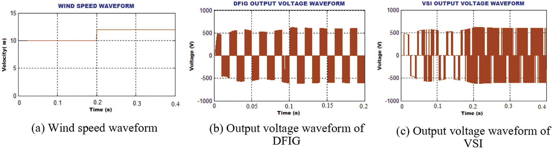
Figure 15: Output measured at Wind turbine side
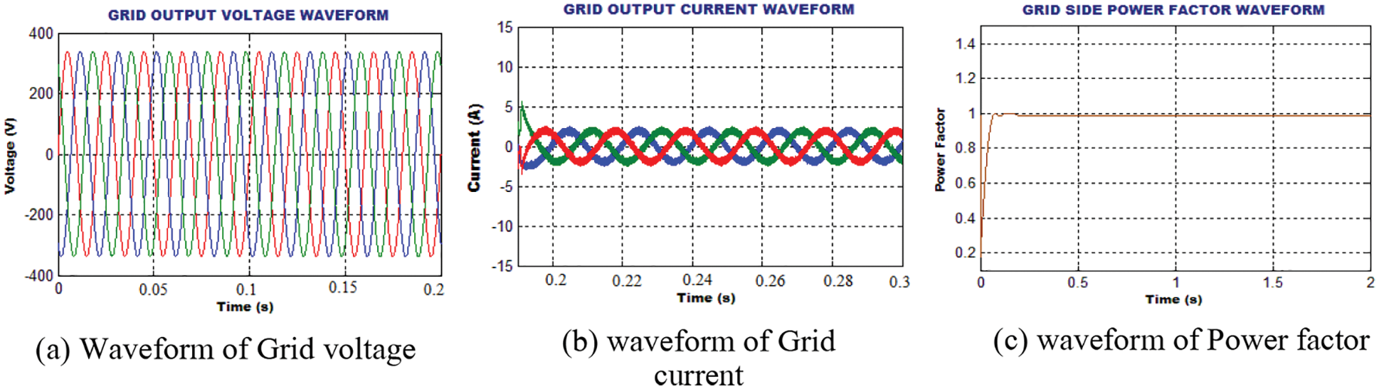
Figure 16: Output measure at grid side
The dc-link voltage stability keeps the fixed voltage of 600 V at the PCC. The Total Harmonic Distortion (THD) value of 2.1% is obtained with the implementation of GWO optimized PI controller whereas the THD of 4.3% is obtained for the conventional PI Controller.
Figs. 17a and 17b show the waveforms of grid current THD with and without optimization in an efficient manner.

Figure 17: THD at the grid side
The FPGA based prototype of the hybrid RE system is established for the experimental investigation of the proposed approach. Fig. 18 represents experimental prototype of 1 kW solar, wind turbine and Battery with GWO-PI controller. The PWM rectifier is regulated by the conventional PI controller. It uses the PCC voltage as the only feedback signal. Inbuilt PWM pulse generators are required by the controllers to drive the controller by using isolated driver system. For the working of an EM relay, the input-output pins are used as the interface. The complete system is controlled by the dsPIC3050 FPGA controller.
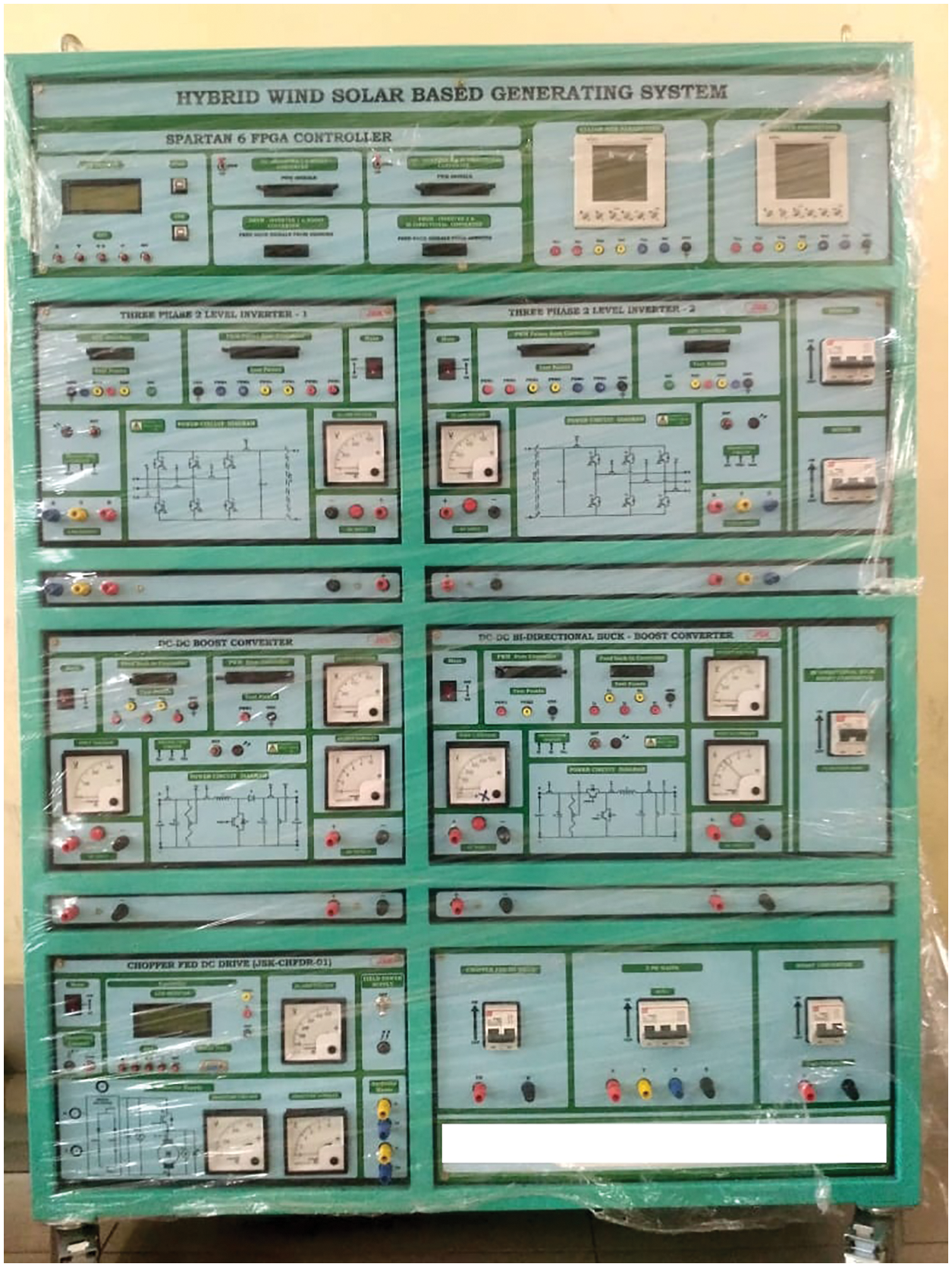
Figure 18: Experimental setup
The experimental outputs are evidently provided in the subsequent section in an efficient manner for validating the proposed approach.
The output current and voltage waveforms are remarkably illustrated in Fig. 19, which validates that the PV outputs are attained with fluctuations.

Figure 19: Voltage and current outputs of PV system
The waveforms indicating the converter output voltage with PI and GWO tuned PI controllers are remarkably portrayed in Fig. 20, which proves that the GWO tuned PI performs well in maintain the constant DC voltage without any oscillation.
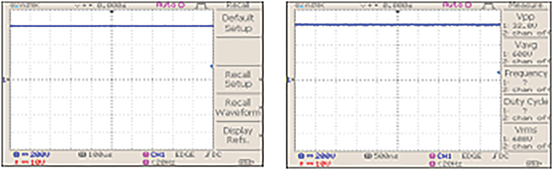
Figure 20: REBOOST LUO Converter output voltage with PI and GWO optimized PI controllers
The output current waveforms of the proposed converter with PI and GWO tuned PI controllers are significantly illustrated in Fig. 21, which validates that the initial fluctuations in the current are settled after some period with the aid of GWO tuned PI controller.
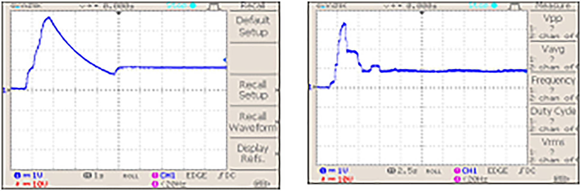
Figure 21: REBOOST LUO Converter output current with PI and GWO optimized PI controllers
The waveforms representing the output voltage of DFIG and PWM rectifier are evidently portrayed in Fig. 22. The intermittent nature of the wind energy causes variations are disruptions in the DFLG output but the PWM rectifier rectifies all these variations and delivers constant output without any fluctuations as represented in the aforementioned figure.
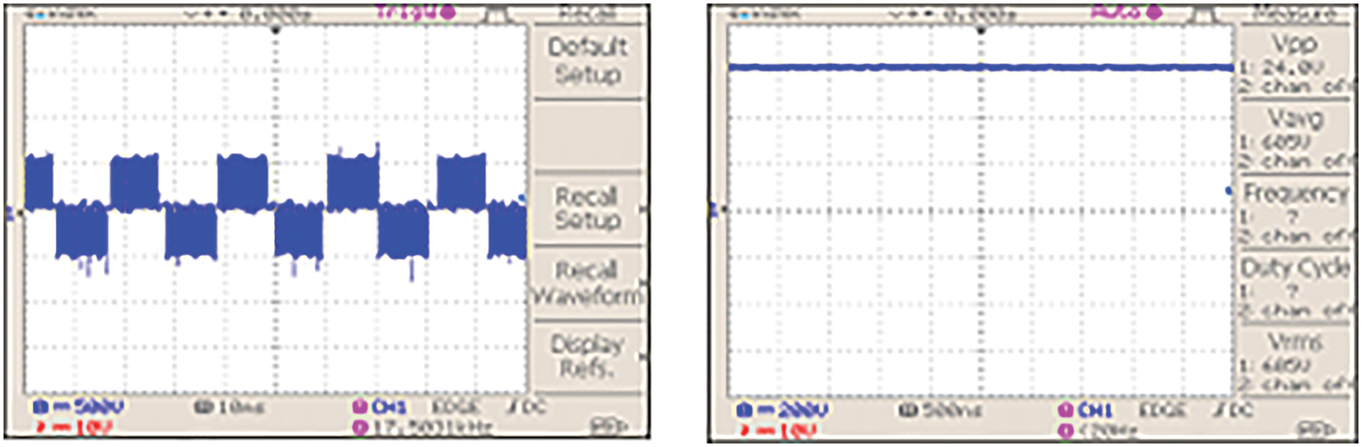
Figure 22: DFIG output voltage and PWM rectifier output
The voltage of battery, PCC voltage and VSI output are respectively illustrated in Figs. 23–25, which validate that constant output voltage is maintained without any disruptions. Hence, the overall performance of the system is extremely enhanced with optimum outcomes.
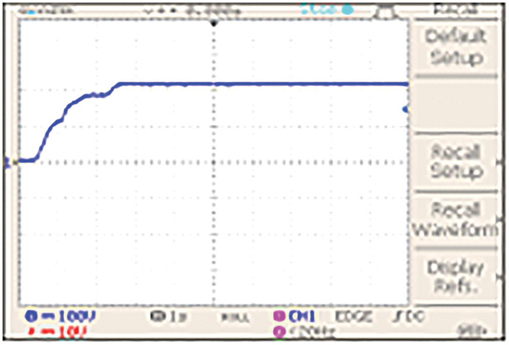
Figure 23: Stored voltage in battery

Figure 24: PCC Voltage
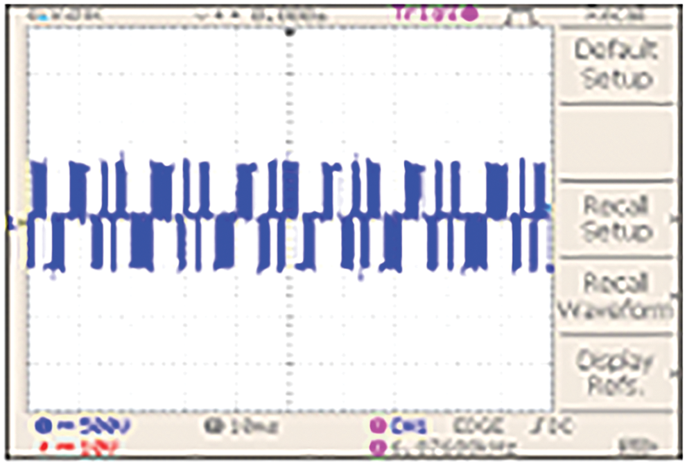
Figure 25: VSI Output voltage
The obtained grid voltage of the developed hardware setup is clearly illustrated in Fig. 26. The line current is sinusoidal and synchronized with the grid voltage, which shows that only real energy is delivered to the grid.
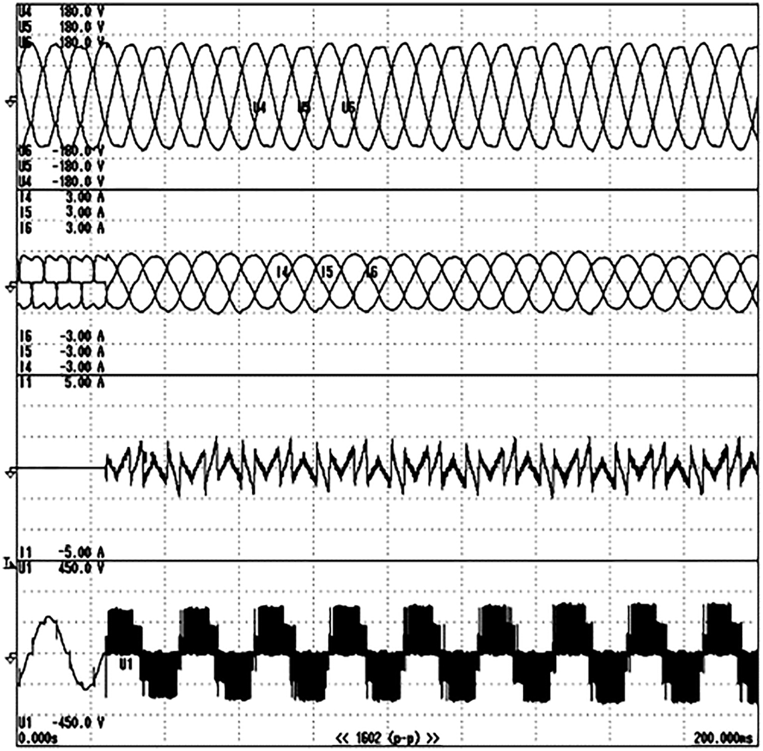
Figure 26: Voltage injected at the grid
The rise time

The performance ability of conventional and GWO optimized PI controllers in maintaining the stable DC-link voltage is evaluated as represented in Fig. 27, which proves that the latter performs well than the former in stabilizing the link voltage in an efficient manner.
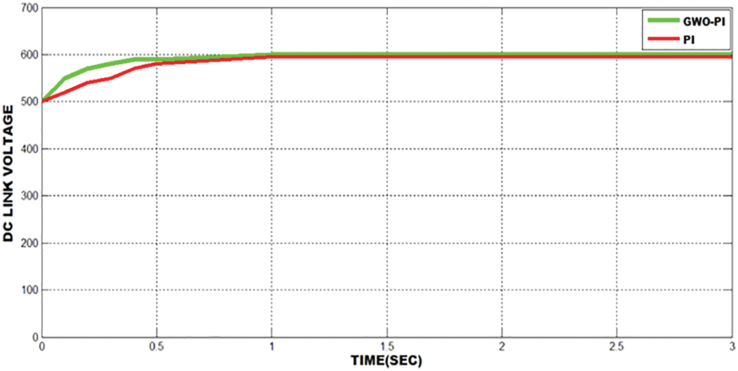
Figure 27: Stabilization DC-link voltage with optimized and conventional PI controllers
Figs. 28a and 28b represent the harmonic element in grid current. The THD value of 2.5% is acquired with GWO-PI controller whereas the THD value of 4.9% is obtained with conventional PI controller. It is thus validated that the proposed approach delivers less THD of 2.5%, which is comparatively better than the conventional PI controller.

Figure 28: THD obtained with (a) PI and (b) GWO-PI controllers
The voltage gain of Reboost Luo converter is improved by increasing the duty cycle. The voltage gain of the proposed converter is compared with other prevailing converters like Boost, CUK, SEPIC and LUO converters. The comparison outputs validate that the proposed converter delivers higher gain ration than the other converters, which is significantly provided in Tab. 2.

The graphical representation of the voltage gain comparison is significantly illustrated in Fig. 29 for emphasizing the eminence of the proposed converter in an optimal manner.
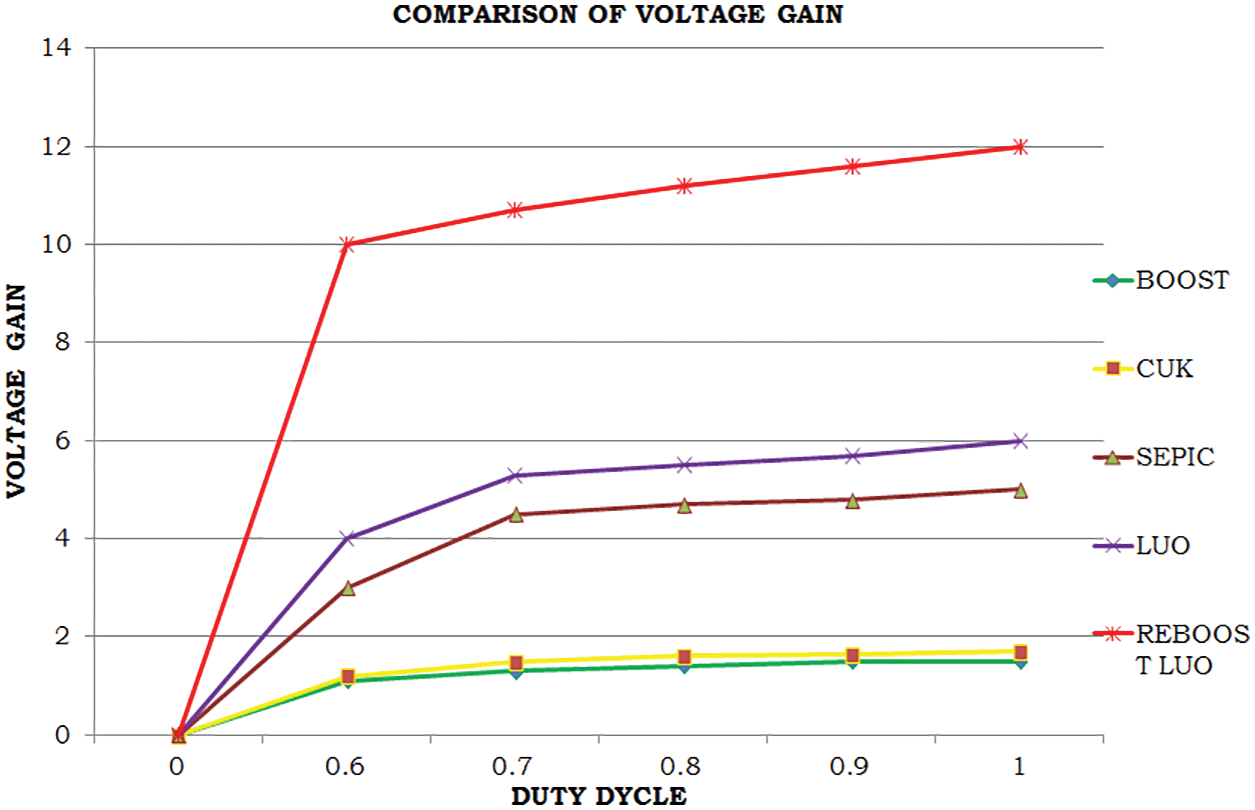
Figure 29: Gain comparison
The performance of the Reboost Luo converter is measured in terms of efficiency. The efficiency of this proposed converter is analogized with other existing converters. Under the given working environment, the boost converter delivers 65% efficiency, which is highly lower than the other converters. The proposed Reboost Luo converter has a optimal efficiency of 98%, which is comparatively better than the other converters. The outcome of this comparative analysis is clearly provided in Tab. 3.

In this work, the implementation of optimized PI controller based Reboost Luo Converter in enhancing the performance of microgrid application is significantly explained. The Reboost Luo converter has maximized the low DC output of PV in a wider range and the converter output is constantly maintained without any fluctuation by employing the GWO tuned PI controller. The bidirectional buck-boost converter links the battery with the PCC to minimize the discontinuous property of renewable energy sources. The charging modes of Battery are controlled by ANFIS to provide energy to the power line when the primary supply has not reached the expected output. The rise and fall energy in the hybrid source are reduced efficiently with GWO-PI controller. The adjusted variables are chosen by minimizing IAE to give better flexibility of the controller. For the step change in input voltage, the dynamic properties of the controller are estimated. In addition, the time domain variables of the controller are successfully extracted with GWO-PI controller. The entire system is validated through MATLAB simulink and the obtained outcomes have highlighted that the proposed methodology delivers optimal THD of 2.1%, which is comparatively better than the prevailing methodologies.
Funding Statement: The authors have received no specific funding for this work.
Conflicts of Interest: The authors have declared that they have no conflicts of interest to report regarding the present work.
References
1. O. M. Babatunde, J. L. Munda and Y. Hamam, “A comprehensive state-of-the-art survey on hybrid renewable energy system operations and planning,” IEEE Access, vol. 8, pp. 75313–75346, 2020. [Google Scholar]
2. N. R. Tummuru, M. K. Mishra and S. Srinivas, “Dynamic energy management of renewable grid integrated hybrid energy s`torage system,” IEEE Transactions on Industrial Electronics, vol. 62, no. 12, pp. 7728–7737, 2015. [Google Scholar]
3. P. Arboleya, C. Gonzalez-Moran, M. Coto, M. C. Falvo, L. Martirano et al., “Efficient energy management in smart micro-grids: Zero grid impact buildings,” IEEE Transactions on Smart Grid, vol. 6, no. 2, pp. 1055–1063, 2015. [Google Scholar]
4. A. Imran, G. Hafeez, I. Khan, M. Usman, Z. Shafiq et al., “Heuristic-based programable controller for efficient energy management under renewable energy sources and energy storage system in smart grid,” IEEE Access, vol. 8, pp. 139587–139608, 2020. [Google Scholar]
5. A. Merabet, K. T. Ahmed, H. Ibrahim, R. Beguenane and A. M. Y. M. Ghias, “Energy management and control system for laboratory scale microgrid based wind-pv-battery,” IEEE Transactions on Sustainable Energy, vol. 8, no. 1, pp. 145–154, 2017. [Google Scholar]
6. T. Shu, X. Lin, S. Peng, X. Du, H. Chen et al., “Probabilistic power flow analysis for hybrid HVAC and LCC-VSC HVDC system,” IEEE Access, vol. 7, pp. 142038–142052, 2019. [Google Scholar]
7. I. Askarian, S. Eren, M. Pahlevani and A. M. Knight, “Digital real-time harmonic estimator for power converters in future micro-grids,” IEEE Transactions on Smart Grid, vol. 9, no. 6, pp. 6398–6407, 2018. [Google Scholar]
8. M. Mosadeghy, R. Yan and T. K. Saha, “A Time-dependent approach to evaluate capacity value of wind and solar PV generation,” IEEE Transactions on Sustainable Energy, vol. 7, no. 1, pp. 129–138, 2016. [Google Scholar]
9. J. Xu, X. Zhao, H. Jing, J. Liang and C. Zhao, “DC fault current clearance at the source side of hvdc grid using hybrid MMC,” IEEE Transactions on Power Delivery, vol. 35, no. 1, pp. 140–149, 2020. [Google Scholar]
10. M. J. Morshed and A. Fekih, “A novel fault ride through scheme for hybrid wind/PV power generation systems,” IEEE Transactions on Sustainable Energy, vol. 11, no. 4, pp. 2427–2436, 2020. [Google Scholar]
11. R. Singh and R. C. Bansal, “Optimization of an autonomous hybrid renewable energy system using reformed electric system cascade analysis,” IEEE Transactions on Industrial Informatics, vol. 15, no. 1, pp. 399–409, 2019. [Google Scholar]
12. R. Singh, R. C. Bansal, A. R. Singh and R. Naidoo, “Multi-objective optimization of hybrid renewable energy system using reformed electric system cascade analysis for islanding and grid connected modes of operation,” IEEE Access, vol. 6, pp. 47332–47354, 2018. [Google Scholar]
13. Z. Zhuo, N. Zhang, J. Yang, C. Kang, C. Smith et al., “Transmission expansion planning test system for AC/DC hybrid grid with high variable renewable energy penetration,” IEEE Transactions on Power Systems, vol. 35, no. 4, pp. 2597–2608, 2020. [Google Scholar]
14. F. Chishti, S. Murshid and B. Singh, “Development of wind and solar based ac microgrid with power quality improvement for local nonlinear load using MLMS,” IEEE Transactions on Industry Applications, vol. 55, no. 6, pp. 7134–7145, 2019. [Google Scholar]
15. L. V. Bellinaso, H. H. Figueira, M. F. Basquera, R. P. Vieira, H. A. Gründling et al., “Cascade control with adaptive voltage controller applied to photovoltaic boost converters,” IEEE Transactions on Industry Applications, vol. 55, no. 2, pp. 1903–1912, 2019. [Google Scholar]
16. R. Errouissi, A. Al-Durra and S. M. Muyeen, “A robust continuous-time MPC of a DC–DC boost converter interfaced with a grid-connected photovoltaic system,” IEEE Journal of Photovoltaics, vol. 6, no. 6, pp. 1619–1629, 2016. [Google Scholar]
17. L. Callegaro, M. Ciobotaru, D. J. Pagano and J. E. Fletcher, “Feedback linearization control in photovoltaic module integrated converters,” IEEE Transactions on Power Electronics, vol. 34, no. 7, pp. 6876–6889, 2019. [Google Scholar]
18. B. Han, J. -S. Lai and M. Kim, “Dynamic modeling and controller design of dual-mode cuk inverter in grid-connected PV/TE applications,” IEEE Transactions on Power Electronics, vol. 33, no. 10, pp. 8887–8904, 2018. [Google Scholar]
19. M. Killi and S. Samanta, “An adaptive voltage-sensor-based MPPT for photovoltaic systems with sepic converter including steady-state and drift analysis,” IEEE Transactions on Industrial Electronics, vol. 62, no. 12, pp. 7609–7619, 2015. [Google Scholar]
20. K. Nathan, S. Ghosh, Y. Siwakoti and T. Long, “A new DC–DC converter for photovoltaic systems: Coupled-inductors combined cuk-SEPIC converter,” IEEE Transactions on Energy Conversion, vol. 34, no. 1, pp. 191–201, 2019. [Google Scholar]
21. J. Ahmed and Z. Salam, “An enhanced adaptive P&O MPPT for fast and efficient tracking under varying environmental conditions,” IEEE Transactions on Sustainable Energy, vol. 9, no. 3, pp. 1487–1496, 2018. [Google Scholar]
22. S. Tang, Y. Sun, Y. Chen, Y. Zhao, Y. Yang et al., “An enhanced MPPT method combining fractional-order and fuzzy logic control,” IEEE Journal of Photovoltaics, vol. 7, no. 2, pp. 640–650, 2017. [Google Scholar]
23. H. Rezk, M. Aly, M. Al-Dhaifallah and M. Shoyama, “Design and hardware implementation of new adaptive fuzzy logic-based MPPT control method for photovoltaic applications,” IEEE Access, vol. 7, pp. 106427–106438, 2019. [Google Scholar]
24. H. Renaudineau, F. Donatantonio, J. Fontchastagner, G. Petrone, G. Spagnuolo et al., “A PSO-based global MPPT technique for distributed PV power generation,” IEEE Transactions on Industrial Electronics, vol. 62, no. 2, pp. 1047–1058, 2015. [Google Scholar]
25. M. C. Mira, Z. Zhang, A. Knott and M. A. E. Andersen, “Analysis, design, modeling, and control of an interleaved-boost full-bridge three-port converter for hybrid renewable energy systems,” IEEE Transactions on Power Electronics, vol. 32, no. 2, pp. 1138–1155, 2017. [Google Scholar]
Cite This Article
 Copyright © 2023 The Author(s). Published by Tech Science Press.
This work is licensed under a Creative Commons Attribution 4.0 International License , which permits unrestricted use, distribution, and reproduction in any medium, provided the original work is properly cited.
 Downloads
 Citation Tools