DOI:10.32604/iasc.2023.027614
| Intelligent Automation & Soft Computing DOI:10.32604/iasc.2023.027614 | |
| Article |
Vision Navigation Based PID Control for Line Tracking Robot
College of Engineering, Muzahimiyah Branch, King Saud University, P.O. Box 2454, Riyadh, 11451, Saudi Arabia
*Corresponding Author: Rihem Farkh. Email: rfarkh@ksu.edu.sa
Received: 21 January 2022; Accepted: 13 March 2022
Abstract: In a controlled indoor environment, line tracking has become the most practical and reliable navigation strategy for autonomous mobile robots. A line tracking robot is a self-mobile machine that can recognize and track a painted line on the floor. In general, the path is set and can be visible, such as a black line on a white surface with high contrasting colors. The robot’s path is marked by a distinct line or track, which the robot follows to move. Several scientific contributions from the disciplines of vision and control have been made to mobile robot vision-based navigation. Localization, automated map generation, autonomous navigation and path tracking is all becoming more frequent in vision applications. A visual navigation line tracking robot should detect the line with a camera using an image processing technique. The paper focuses on combining computer vision techniques with a proportional-integral-derivative (PID) controller for automatic steering and speed control. A prototype line tracking robot is used to evaluate the proposed control strategy.
Keywords: Line tracking robot; vision navigation; PID control; image processing; OpenCV; raspberry pi
Many industry participants are currently interested in adopting autonomous mobile robots in their factories, which is one of the fourth industrial revolution’s foundations (IR4.0) [1,2]. Mobile robots are commonly employed to assist humans in performing difficult tasks in agriculture, industry, military, and search & rescue [3–7]. Robots are capable of doing tasks effectively and contributing to human lives. Mobile robots are often ones that can move from one location to another to do desired and challenging activities [8,9]. A mobile robot, for example, is employed in Urban Search and Rescue (USAR) to locate people and help rescue them in emergencies such as earthquakes or terrorist attacks. [10].
A mobile robot that is programmed to follow a line or a path is known as a line-tracking robot. The path is usually predetermined and can be visible (for example, a black line on a white surface with high contrast colors) or invisible (for example, a magnetic field). [11–13]. Various sensing systems can be used to identify these unique markers or lines. These techniques can range from basic, low-cost line sensor circuits to complex vision systems. Automated guided vehicles (AGVs) are the most common usage of line-tracking robots in the industry (Fig. 1). They are most commonly employed in industrial settings to move heavy goods across a vast industrial structure, such as a factory or warehouse. The line might indicate the path between a storage shelf and a loading bay, or between a robot charging station and the robot’s work area [14].
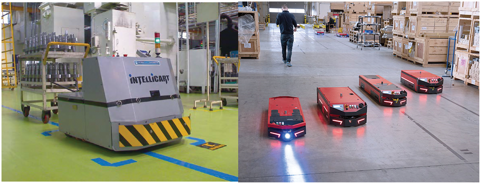
Figure 1: Automated guided vehicles – line-tracking robots
In this paper, we propose to improve the traditional line-tracking robot with IR sensors by combining computer vision techniques with cascade PID controllers for the robot’s speed control.
2 Line Tracking Robot Architecture
This section describes the architecture and system block. First, a suitable configuration was selected to develop a line-tracking using a Pi camera connected through RPi3 B+ to the motor driver IC. Fig. 2 illustrates this configuration.
The camera has a wide field of vision, and the sensor is pointed to the path line. Encoders are mounted above the wheels that will be utilized (Fig. 3). To prevent a robot from toppling over, heavy things, particularly batteries, should be stored below the center of gravity.
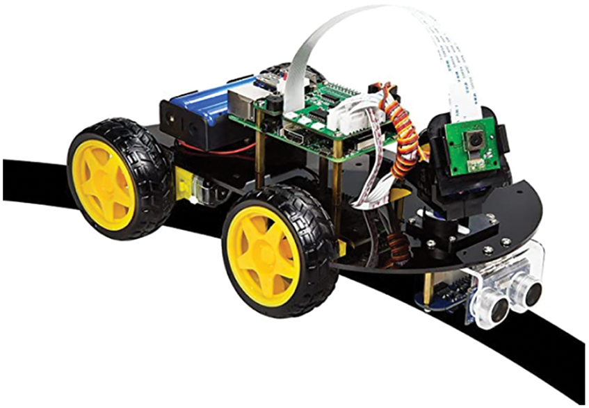
Figure 2: The line-tracking robot
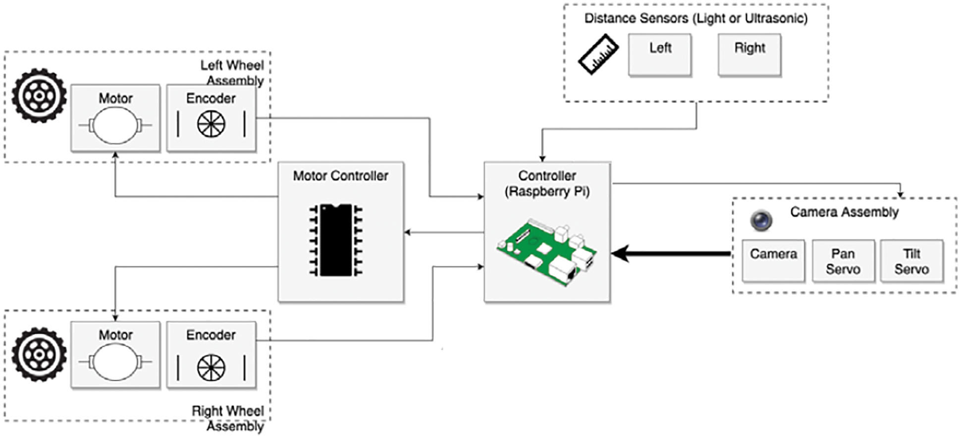
Figure 3: The line-tracking robot diagram
Our robot is made up of the following components:
The Raspberry Pi is widely regarded as the most successful credit card-sized system-on-chip (SoC) of the last decade. It was developed in the United Kingdom (UK) by the Raspberry Pi Foundation. Its small form size, versatility, and low cost (prices range from around $10 for the tiny single-core Raspberry Pi Zero to over $80 for a quad-core Raspberry Pi 4 with 8GB of RAM) have made it a popular choice for many IoT applications [15].
The Raspberry Pi 3 B+ is powered by a 1.2 GHz ARM Cortex – A53 Broadcom BCM 2837 Processor. The notable change is the quad-core ARM Cortex A53 (ARMv8) cluster, which operates at 1.2 GHz and is 50% faster than the Raspberry Pi 2 model. Fig. 4 presents a simplified component arrangement of the Raspberry Pi Model 3.
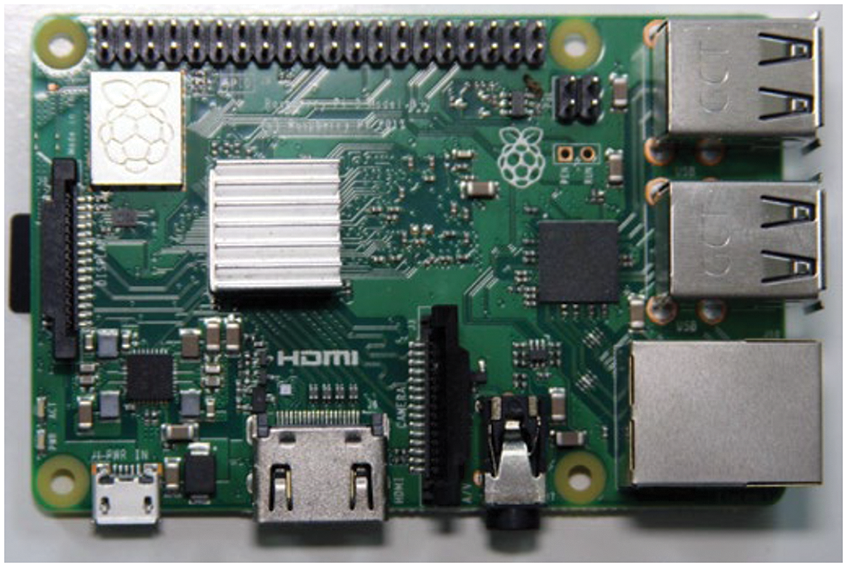
Figure 4: Component arrangement of the Raspberry Pi Model 3
The Raspberry Pi board has 40 general-purpose input-output (GPIO) pins. These pins allow the Raspberry Pi to communicate with the outside world. The Raspberry Pi can control physical devices like motors, expansion boards, and LEDs via these ports. Raspbian is the chosen operating system for Raspberry Pi. Raspbian is based on Debian, a Linux-based operating system that has been heavily tweaked for Raspberry Pi devices.
2.2 Raspberry Pi Camera Module
The Raspberry Pi camera (Fig. 5) module attaches to a Raspberry Pi and allows it to take pictures. It will be used for programming visual processing. Images or video sequences are captured using this module [15].
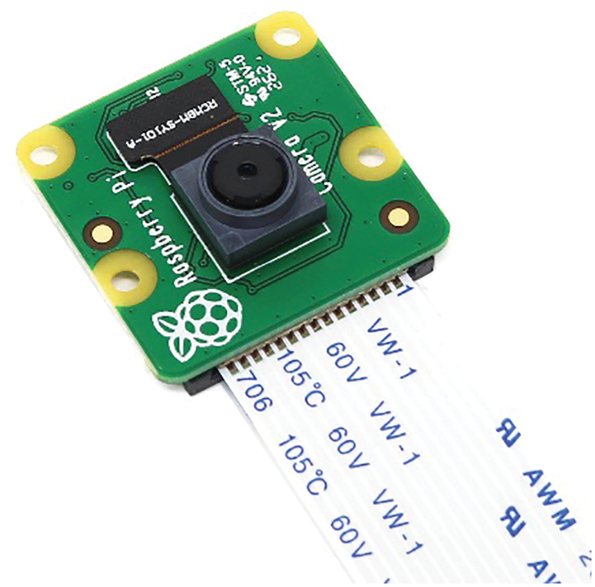
Figure 5: Raspberry Pi camera module
2.3 Ultrasonic Distance Sensor
The HC-SR04 (Fig. 6) is a distance/ranging sensor that detects distance by bouncing sound pulses off objects. It is impacted by the sort of material used to make an item and will miss specific surfaces, but it is unaffected by lighting conditions [16].
Some surfaces, such as textiles, absorb too much sound and never return it, while others, such as grids or meshes, do not interact with sound waves and are transparent to the sensor.
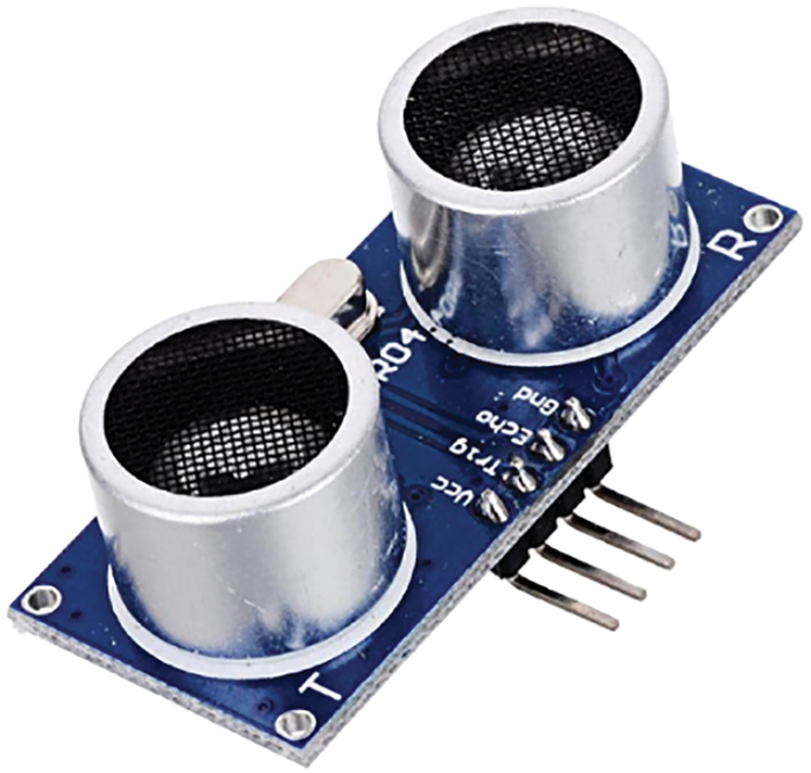
Figure 6: Ultrasonic distance sensor
Servo motors (Fig. 7) are employed in pan and tilt mechanisms. This type of motor includes a gear motor, a sensor, and a built-in controller. A signal indicates a motor position, and the controller attempts to attain this position using feedback from the sensor [16].
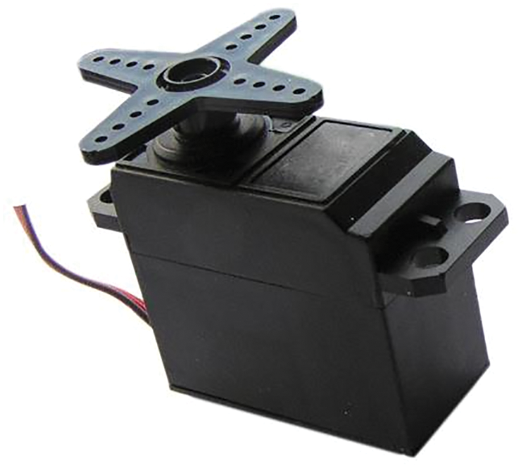
Figure 7: Servo motor
It is a DC motor that has a gearbox attached to it. This gearbox reduces speed while increasing torque handling capacity. The motor’s capacity to move a load is enhanced by this mechanical advantage (Fig. 8) [16].
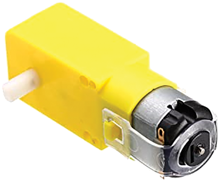
Figure 8: DC motor
A motor encoder is a rotary encoder that is attached to an electric motor and delivers closed-loop feedback signals by tracking the speed and/or the position of the motor shaft.
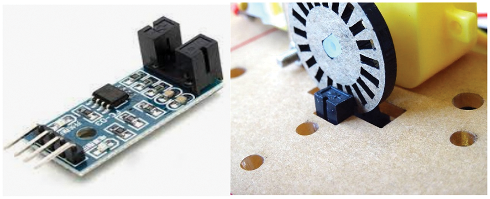
Figure 9: Encoder speed optical sensor module FC-03
The FC-03 (Fig. 9) is an optical beam sensor (Opto switch, phototransistor) with digital and analog outputs.
It is a high voltage, high current twin full-bridge driver designed to handle conventional TTL logic levels and drive inductive loads such as relays, solenoids, DC and stepping motors. The L298N (Fig. 10) requires four I/O pins for the DC motors [16].
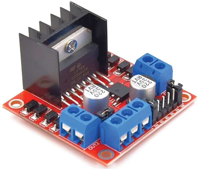
Figure 10: LN298 IC motor driver
3 Image processing Controller Design Based PID for Line Tracking Robot
The data flow in Fig. 11 begins with camera pictures. These are subject to visual processing to extract information from images such as lines, contours, and frame centers. We start by searching the contour and frame center locations from the picture. These values are sent into a speed Proportional Integral Derivative (PID) controller, which likewise has the frame center as its set point. This PID will output a speed for the motors and keep the robot on the black line based on the difference between the frame center and the actual contour center. This is the base common speed (direction speed) for both motors.
The center of contour position has a x component and a y component. We’re interested in the x coordinate since the robot will pivot to the center of the contour. The x coordinate is used by PID to regulate the direction/heading. This PID uses the camera frame’s center as a reference point (Fig. 11). In this direction, PID will provide an output in an attempt to reduce the difference between these coordinates to zero.
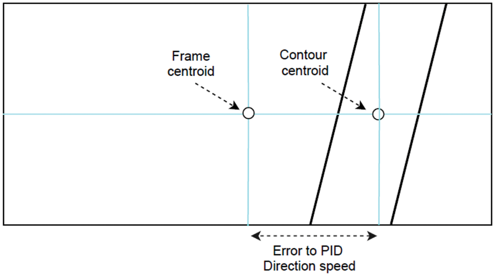
Figure 11: Error calculation for the PID_Direction speed. Error = Frame centroid – Contour centroid
By increasing the speed of one motor and decreasing the speed of the other, the robot will turn to the black line. The right and left speeds are used to adjust the duty cycle of the PWM applied to the motor driver IC’s input pins (Fig. 12). The Right and left speeds of the motors are described by the following equations:
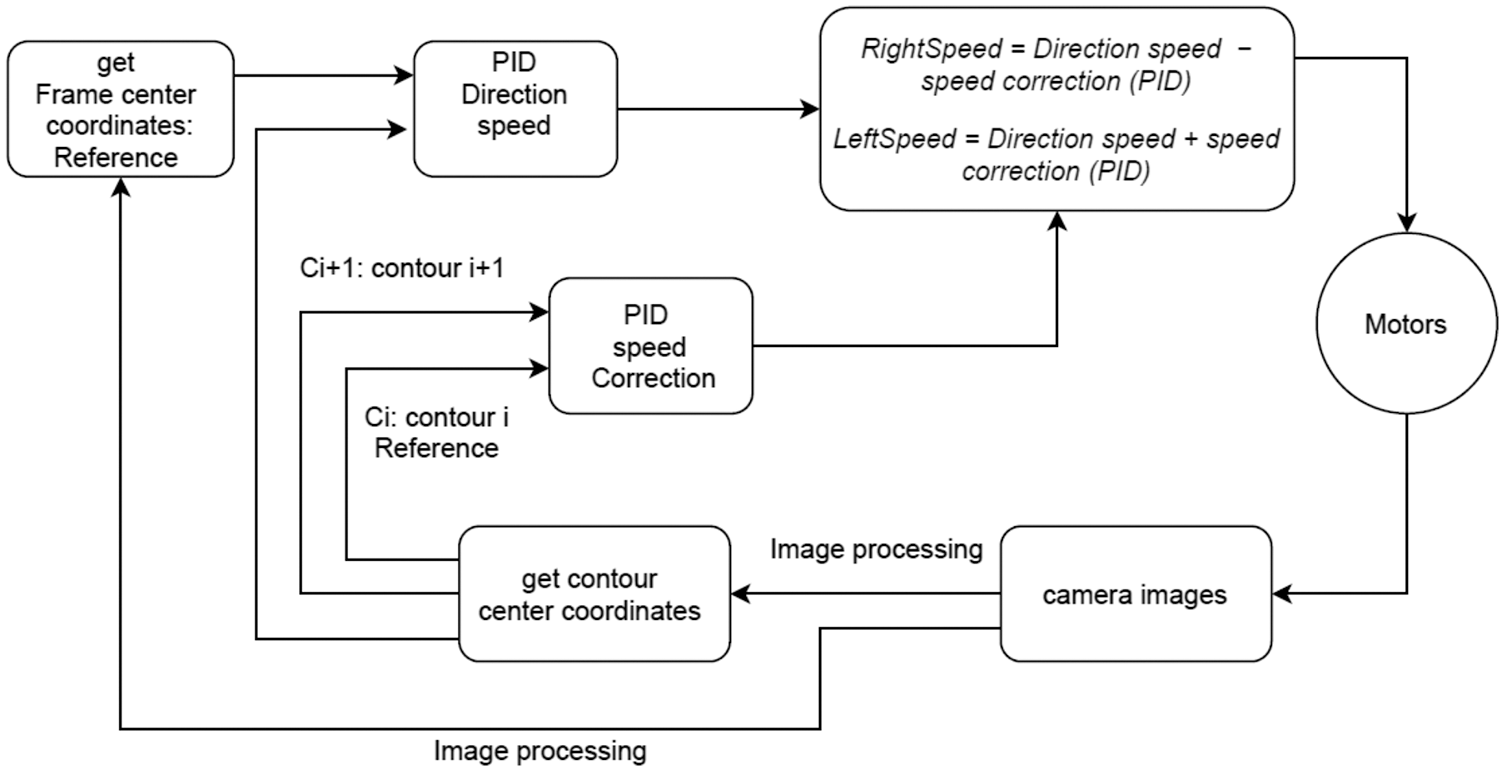
Figure 12: PID control scheme for line tracking robot
The first PID determines the speed direction by taking the frame centroid as a reference position. The second PID tries to reduce the error between two successive contours centroids to zero by giving a speed correction (Fig. 13).
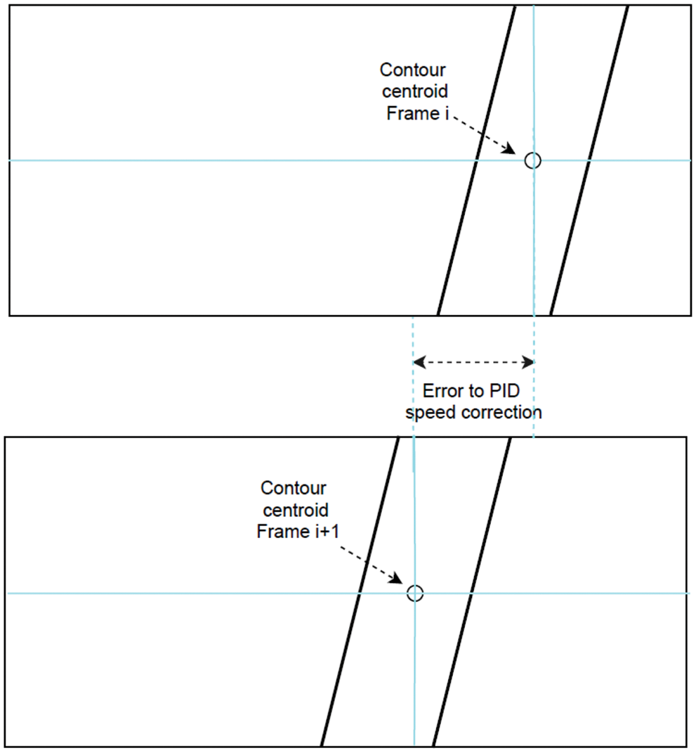
Figure 13: Error calculation for the PID_speed correction. Error = Contour centroid (Frame i+1) - Contour centroid (Frame i)
Optical incremental encoders are frequently employed in control systems to provide position readings at a predetermined sampling frequency. Encoder feedback combined with a PID controller can be used to control the speed of a DC motor in response to load disturbances and noise.
The Right speed and left speed signals will be used to generate the motor speed set-points for the robot. The speed control is tuned to make the robot move according to the speed set-point input using 2 PID controllers (Fig. 14).
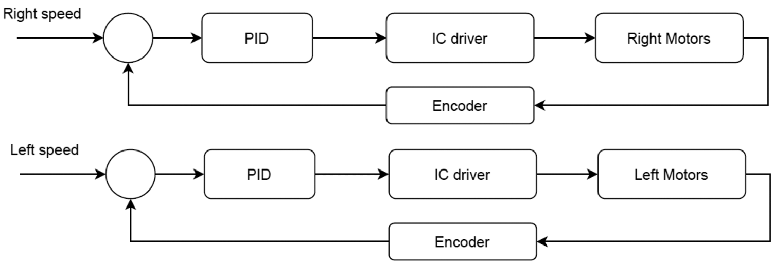
Figure 14: PID control speed with encoder
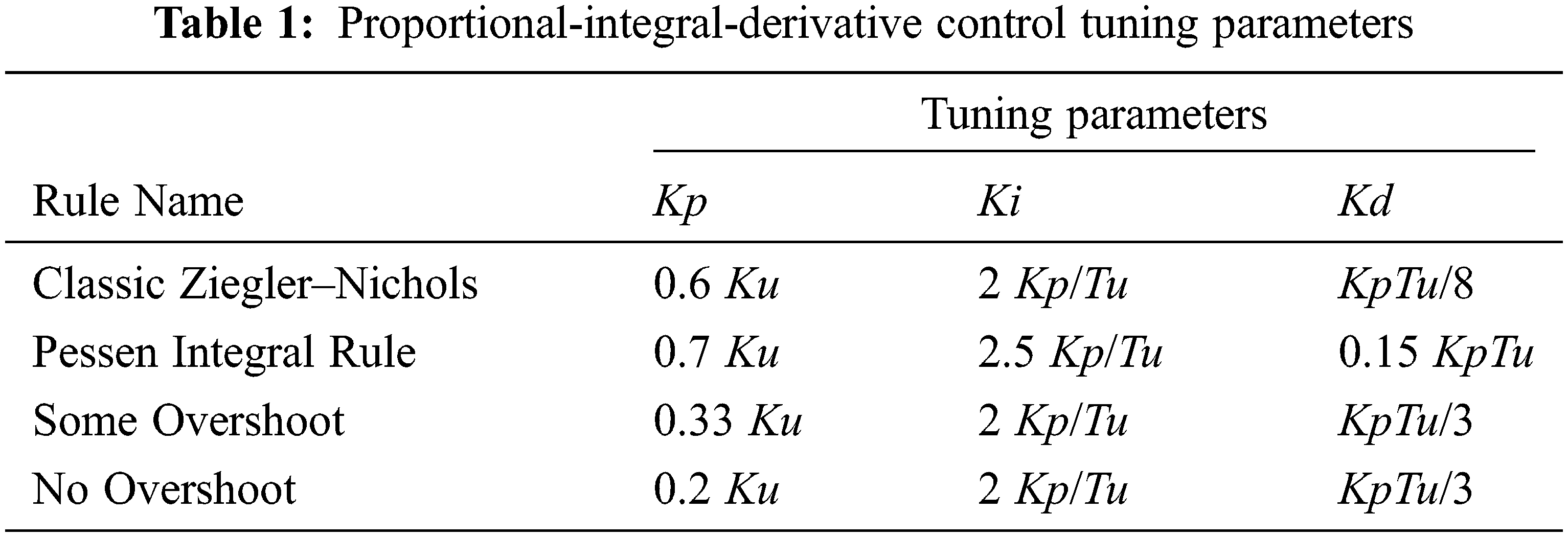
We begin with a proportional constant of 0.1 and gradually increase it until the robot begins to overshoot and continuously oscillate, at which point we take half of the proportional constant value (Ku). To tune the Ki and Kd parameters, the Ku and Tu (oscillation period) were used (Tab. 1) [17]. Tuning PIDs is a long process: get the robot on the black line and tune direction PID till it’s very good, then return for speed PID.
The PID controller equation is changed for discrete implementation by applying the reverse Euler method for numerical integration.
Because of the variations in line curvature, a traditional PID controller was found to be inadequate for the line-tracking robot after extensive testing. Only the last three error numbers were taken instead of adding all preceding values to fix this problem. took. The updated controller equation is as follows:
OpenCV (Open Source Computer Vision Library) is a free and open-source software library for computer vision and machine learning. OpenCV was created to offer a standard foundation for computer vision applications and to speed up the incorporation of machine perception into commercial products [18].
3.3 Line-Tracking Algorithms Implementation on Raspberry Pi
The line tracking algorithm is written in python and runs on a Raspberry Pi 3 (Model B+). The algorithm receives a video stream from a 5-megapixel camera and uses some OpenCV library functions to process the images. Because this is a time-sensitive application, the camera is set to its maximum available frame rate of 90 fps. The resolution is limited to 640 x 480 in this case.
• We start by importing some libraries like NumPy, cv2
• Next we set up the video feed:
• The first line specifies which camera will be utilized. If you set it to –1, it will use a random camera; however, you may adjust the number to select which one to use if you have numerous cameras connected. The width and height of the video input are defined by the second and third lines. The video size is 640 x 840 pixels.
• Now, we take the current frame and crop it as follows: Cropping is necessary so that the robot only looks at the portion of the line nearest to it, rather than a portion of the line further down the track.
• Convert the image to grayscale and blur it with a Gaussian blur
• We convert the image to grayscale since we are only interested in black lines on a white background. Following that, we use a Gaussian blur to remove any noise from the image.
• Threshold the image: A color threshold will transform the image into a boolean image. Any pixel below 60 will turn white, while any pixel beyond that color will turn black.
• Identify the contours: We want openCV to identify all of the forms we’ve thresholded for (the black line) so we can analyze them in the future stage.
• Find the center of the biggest contour: The first line determines if any contours are detected.
• If any contours are identified, it picks the one with the largest area and then gets the center X and Y coordinates (Cx and Cy) of that contour.
• draw shapes and lines onto the original cropped image.
• Find the center of the current frame, get the center coordinates (Fx and Fy)
• Feed the PID controller by the error E = Fx-Cx
• Generate the speed control signal to the motors
Fig. 15 shows how to find the contour on the black line and its centroid. We used some functions from Opencv to achieve it.
• Capture the frames : ret, frame = video_capture.read()
• Crop the image : crop_img = frame [60:120,0:160]
• Convert to grayscale : gray = cv2.cvtColor(crop_img, cv2.COLOR_BGR2GRAY)
• Gaussian blur: blur = cv2.GaussianBlur(gray,(5,5),0)
• Color thresholding : ret,thresh = cv2.threshold(blur,60,255,cv2.THRESH_BINARY_INV)
• Find the contours of the frame: contours, hierarchy = cv2.findContours(thresh.copy(), 1, cv2.CHAIN_APPROX_NONE)
• Find the centroid: cv2.moments, cv2.contourArea
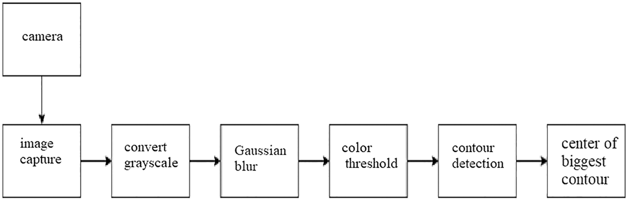
Figure 15: Finding contour techniques using OpenCV
We presented a vision-based line-tracking robot. We proposed a cascade PID controllers with image processing techniques that provide a satisfactory result. In this study, we have used Raspberry Pi and a camera to monitor the robot and to guarantee a smooth line following behavior. More advanced techniques based on deep learning, PID and vision control could be developed in the future.
Acknowledgement: The authors acknowledge the support of King Saud University, Riyadh, Saudi Arabia.
Funding Statement: The authors received specific funding from the researchers supporting project number (RSP2022R474), King Saud University, Riyadh, Saudi Arabia.
Conflicts of Interest: The authors declare that they have no conflicts of interest to report regarding the present study.
1. F. Farbord, Autonomous Robots. Springer International Publishing, Boston, pp. 1–13, 2020. [Google Scholar]
2. R. Siegwart and I. R. Nourbakhsh, Introduction to Autonomous Mobile Robots. Cambridge, A Bradford Book, The MIT Press, pp. 11–20, 2004. [Google Scholar]
3. N. Saqib and M. M. Yousuf, “Design and implementation of shortest path line follower autonomous rover using decision making algorithms,” in Asian Conf. on Innovation in Technology (ASIANCON), India, pp. 1–6, 2021. [Google Scholar]
4. J. Gonçalves, V. H. Pinto and P. Costa, “A line follower educational mobile robot performance robustness increase using a competition as benchmark,” in 6th Int. Conf. on Control, Decision and Information Technologies (CoDIT), France, pp. 934–939, 2019. [Google Scholar]
5. S. Mahajan, N. Mittaland and A. K. Pandit, “Image segmentation using multilevel thresholding based on type II fuzzy entropy and marine predators algorithm,” Multimedia Tools and Applications, vol. 80, no. 13, pp. 19335–19359, 2021. [Google Scholar]
6. S. Mahajan and A. K. Pandit, “Hybrid method to supervise feature selection using signal processing and complex algebra techniques,” Multimedia Tools and Applications, vol. 80, no. 4, pp. 33015–33027, 2021. [Google Scholar]
7. K. J. Singh, A. Nayyar, D. V. Kappor, N. Mittal, S. Mahajan et al., “Adaptive flower pollination algorithm-based energy efficient routing protocol for multi-robot systems,” in IEEE Access, vol. 9, pp. 82417–82434, 2021. [Google Scholar]
8. S. Tayal, H. P. G. Rao, S. Bhardwaj and H. Aggarwal, “Line follower robot: Design and hardware application,” in 8th Int. Conf. on Reliability, Infocom Technologies and Optimization (Trends and Future Directions) (ICRITO), India, pp. 10–13, 2020. [Google Scholar]
9. A. S. Simonsen and E. L. M. Ruud, “The application of a flexible leader-follower control algorithm to different mobile autonomous robots,” in IEEE/RSJ Int. Conf. on Intelligent Robots and Systems (IROS), Las Vegas, vol. 2020, pp. 11561–11566, 2020. [Google Scholar]
10. A. A. Santoso Gunawan, J. Dede, M. D. Mennawi, H. Ngariante, W. Budiharto et al., “Line follower smart trolley system V2 using RFID,” in 1st Int. Conf. on Computer Science and Artificial Intelligence (ICCSAI), South Africa, pp. 17–21, 2021. [Google Scholar]
11. R. Farkh, K. A. Jaloud, S. Alhuwaimel, M. T. Quasim and M. Ksouri, “A deep learning approach for the mobile-robot motion control system,” Intelligent Automation & Soft Computing, vol. 29, no. 2, pp. 423–435, 2021. [Google Scholar]
12. R. Farkh, M. T. Quasim, K. Al jaloud, S. Alhuwaimel and S. T. Siddiqui, “Computer vision-control-based CNN-PID for mobile robot,” Computers, Materials & Continua, vol. 68, no. 1, pp. 1065–1079, 2021. [Google Scholar]
13. R. Farkh, H. Marouani, K. A. Jaloud, S. Alhuwaimel, M. T. Quasim et al., “Intelligent autonomous-robot control for medical applications,” Computers, Materials & Continua, vol. 68, no. 2, pp. 2189–2203, 2021. [Google Scholar]
14. J. Sankari and R. Imtiaz, “Automated guided vehicle (AGV) for industrial sector,” in 10th Int. Conf. on Intelligent Systems and Control (ISCO), India, pp. 1–5, 2016. [Google Scholar]
15. A. Radovici and I. Culic, Getting Started with Secure Embedded Systems: Developing IoT Systems for micro: Bit and Raspberry Pi Pico Using Rust and Tock. Berkeley, Apress, pp. 11–15, 2022. [Google Scholar]
16. J. Cicolani, Beginning Robotics with Raspberry Pi and Arduino: Using Python and OpenCV. Berkeley, Apress, pp. 11–15, 2022. [Google Scholar]
17. Y. Pan, X. Li and H. Yu, “Efficient PID tracking control of robotic manipulators driven by compliant actuators,” "IEEE Transactions on Control Systems Technology, vol. 27, no. 2, pp. 915–922, 2019. [Google Scholar]
18. J. Howse and J. Minichino, Learning OpenCV 4 Computer Vision with Python 3: Get to Grips with Tools, Techniques, and Algorithms for Computer Vision and Machine Learning. Packt Publishing, pp. 40–80, 2020. [Online]. Available: https://www.amazon.sa/dp/1789531616. [Google Scholar]
 | This work is licensed under a Creative Commons Attribution 4.0 International License, which permits unrestricted use, distribution, and reproduction in any medium, provided the original work is properly cited. |