DOI:10.32604/iasc.2023.027388
| Intelligent Automation & Soft Computing DOI:10.32604/iasc.2023.027388 | |
| Article |
Optimum Design of Stair-Climbing Robots Using Taguchi Method
1Department of Mechanical Engineering, E.G.S. Pillay Engineering College, Nagapattinam, Tamilnadu, India
2Department of Mechanical Engineering, QIS College of Engineering and Technology, Ongole, Andhra Pradesh, India
*Corresponding Author: A. Arunkumar. Email: aarunkumaregs@gmail.com
Received: 16 January 2022; Accepted: 01 March 2022
Abstract: Environmental issues like pollution are major threats to human health. Many systems are developed to reduce pollution. In this paper, an optimal mobile robot design to reduce pollution in Green supply chain management system. Green supply chain management involves as similating environmentally and economically feasible solutions into the supply chain life-cycle. Smartness, advanced technologies, and advanced networks are becoming pillars of a sustainable supply chain management system. At the same time, there is much change happening in the logistics industry. They are moving towards a new logistics model. In the new model, robotic logistics has a vital role. The reasons for this change are the rapid growth of the e-commerce business and the shortage of workers. The advantages of using robotic logistics are reduction in human errors, faster delivery speed, better customer satisfaction, more safety for workers, and high workforce adaptability. A robot with rocker-bogie suspension is a six-wheeled mobile platform that has a distinctive potential to keep all wheels on the ground continuously. It has been designed to traverse rough and uneven terrain by distributing the load over its wheels equally. However, there is a limitation to achieving high-speed mobility against vertical barriers. In this research, an optimal design of product delivery wheeled robots for a sustainable supply chain system is proposed to ensure higher adaptability and maximum stability during climbing staircases. The design parameters of the proposed robot are optimized using Taguchi Method. The aim is to get a smooth trajectory of the robot’s center-of-mass. The proposed approach realizes a robot with much-improved stability which can climb over heights more than the size of the wheel (i.e., 3 times the radius of wheels). The results reveal that the modified rocker-bogie system not only increases the stair-climbing capability but also thwarts instability due to overturning of a wheel of the robot.
Keywords: Green supply chain management; robotic logistics; stair-climbing wheeled mobile robot; optimum design; rocker-bogie mechanism; taguchi method
Poor air quality and pollution are causes of diseases and death. According to a recent survey, 9 million deaths per year are caused by pollution. Metro cities and industrial areas are major affected areas in the world. Many research studies tried many solutions for reducing pollution [1–3]. In 2018, ITMO University researchers tried to use mobile robots and sophisticated sensors for air pollution monitoring. They used waterborne robots and an aerial drones. Portable gas analyzers and gas sensors in the robot and drone measured greenhouse gases (CO, CO2, NO, SO2) presence in the air and water surface. Their research successfully proved that robots and drones can be effectively used for monitoring greenhouse gases [4–6]. Autonomous mobile robots can be used for data collection about pollution in particular locations and systems like Supply chain management. They do data collection in a scalable and more flexible way in comparison to other techniques. Advanced decentralized technologies like blockchain allow us to get data with the best consistency. Using these technologies, data manipulation issues like double-counting, manipulations by male factors, lack of trust and fraud, etc can be avoided [7,8]. This work focused on the eight-wheeled robot with rocker-twin bogies mechanism which has the benefit of linear bogie movement in protecting the entire vehicle from overturning problems while performing high-speed operations. The objective of present work is to optimize the stair-climbing robot design with the modified suspension mechanism which can traverse the steps with a height more than the wheel’s diameter. To get a smooth trajectory of Centre of Mass (CM), the design parameters of the proposed robot are optimized using Taguchi Method. The traversability of the prototype robot is verified through experiments. The experimental results reveal that the proposed mechanism surmounts the design restrictions, environmental obstacles more easily than the conventional rocker-bogie system. This rocker-twin bogies system possesses considerably improved stability during motion in staircases and also provides higher speed operation with the same stair climbing ability thrice the wheel diameter.
The remaining sections of this article are as follow Section 2 reviews the related works about robots with a rocker-bogie suspension system. In Section 3, the mechanism behind conventional rocker-bogie suspension and the overturning problem associated with the conventional system are discussed. A new performance metric, Index of Instability, introduced for smooth running and traversability of some renowned wheeled mobile robots, is assessed using this metric. Section 4 presents the system design for the new rocker-twins bogie mechanism based on the kinematic analyses. In Section 5, the optimization procedure using Taguchi method is discussed and a comparison is made with the achieved optimal robot design with others. From the viewpoints of traversability and smooth running, the extensive experiments using the proposed eight-wheeled robot with the rocker-twins bogies mechanism are carried out in Section 6. At last, Section 7 concludes this research work.
Already, a few researchers have attempted to apply mobile robots to pollution mitigation. Sathiya et al. [9] used mobile robots to reverse the process of Sustainable Supply Chain Management (SSCM). They applied it to a real-world issue — the use of mobile robots at India’s Maruti True Value Company. They noted that the use of mobile robots to combat pollution leads in greater benefits for humans. Hanafi et al. [10]. Employed a mobile robot to collect data on air pollution via telemetry. They determined that mobile robots are capable of efficiently collecting data on air pollution via technologies such as Bluetooth. Gonzalez-de-Soto et al. [11] reduced air pollution by the deployment of robotic tractors. They conducted research on precision agriculture. According to their studies, using robots in agriculture results in a 50% reduction in air pollution. Saada [12] emphasised the several benefits associated with the usage of mobile robots in green SCM. The benefits include a reduction in environmentally detrimental characteristics such as greenhouse emissions and air pollution. Additionally, mobile robots cut losses and wastages while increasing productivity and profitability. Mobile robots assist both industry and society. Aguiar et al. [13] highlighted the effective adoption of mobile robots (AGVs) in a Brazilian industry’s supply chain management (SCM) system. Jiang et al. [14] presented a new passively-actively transformable mobile robot capable of traversing unstructured terrain in 2019. When traction and stability were necessary, the robot’s locomotion model could adapt to the difficult terrain conditions by utilising a novel movable side frame. The constructed robot passively adjusted to diverse terrain conditions by using the balance-rocker method to ensure that all four wheels were in touch with the ground. The kinematic method described in this article served as a theoretical foundation for designing, analysing performance, and controlling posture. The proposed mobile robot might be used for a variety of purposes, including disaster relief, rough-terrain planetary exploration, and rescue missions.
Numerous researchers described how the rocker-bogie mechanism utilised in the Mars Exploration Rover (MER) mission was able to accomplish multiple objectives while emphasising the design’s varied implementations and latch systems [15–18]. Additionally, rocker-bogie configurations permit stowing within the current area and assembling the robot in such a way that it can safely depart from the lander and search the extraterrestrial surface. Ullrich et al. [19] optimised the kinematics and wheel size using the Genetic Algorithm. After 100 iterations, the driving mechanism’s overall fitness was increased by an average of 28%. This approach would be used in a variety of robots to optimise the dimensions of the wheels. Lindemann et al. [20] provided details on the robot’s mobility assembly and mechanical hardware. The authors created and analysed a prototype model’s mobility performance. The robot’s traversability on a Mars-like surface with soft soils, rocks, and craters was investigated, and the system’s design was confirmed with relevant tools. In 2020, Ryu et al. [21] published Shape-Morphing Wheel Design and Analysis for High-Speed Locomotion Step Climbing. Typically, the size of the wheels on wheeled mobile robots limits their ability to conquer steps. Have proposed a shape-shifting wheel device for rapid step climbing. The authors offer the findings of a comprehensive investigation of design problems. The results demonstrate that a robot equipped with morphing wheels is capable of climbing a 46.67 mm obstacle at a speed of 1.82 m/s, which is 1.33 times the radius of the wheel. According to the researchers, this strategy should be applicable to different kinds of locomotion for wheeled mobile robots. Finally, a kinematic study is performed on the suggested system to illustrate the robot’s capacity to climb stairs. The results indicate that the improved rocker-bogie system not only improves stair climbing performance but also prevents the robot from becoming unstable owing to a wheel overturning.
This section gives information regarding the conventional rocker-bogie mechanism and its drawbacks faced by the conventional system, followed by the proposed stair climbing robot with rocker- bogie mechanism that overcomes the drawbacks seen in the conventional model.
3.1 Problem of Overturning in Conventional Rocker-Bogie Suspension System
Before designing a new suspension system, a comprehensive kinematic study of suspension mechanism on a rough surface is performed to explore the impacts of lifted wheels against resultant variations in height value and pitch angle (HPA), which is diplomatically used to put forward an innovative stair-climbing product delivery robot. The key challenge of the conventional rocker-bogie suspension systems employed in product delivery robots is their low-speed traversability which derails the rhythm to engross the vibrations produced by wheels shown in Fig. 1. The low-speed traversability remains a consequence of the following aspects:
• To step over vertical barriers, the product delivery robot must be decelerated considerably to provide adequate thrust to lift the mass of the mobile platform. Subsequently, this decreases the average speed of the robot which cannot be accepted in the supply chain management system.
• If the product delivery robot is moving with high speed and meets a barrier (height more than the diameter of the wheel), there will be a large vibration transferred over the frame which could impair the system or topple down the whole robot.
Even though obstacle dimensions can be different, the most challenging geometry which can be traversed by a product delivery robot is a step or staircase type quadrilateral obstacle shown in Fig. 3. When driving on smooth terrain, if there is no slippage, the wheel center will travel on a straight line parallel to the surface with constant speed. Fig. 3. represents a scenario where the radius of wheel is equal to or greater than the height of the obstacle. In this case, Instantaneous Center-of-Rotation (ICR) of the wheel is positioned at the point of contact of the wheel and obstacle. The trajectory of the wheel centers creates a smooth curve; hence, its horizontal movement does not interrupt, also denotes a situation where the wheel radius is less than the height of the obstacle. This situation can be categorized as climbing. The climbing motion contains two components: (i) a soft rotational movement with the instantaneous center of rotation (ICR_h) at the corner, and (ii) a vertical movement that generates a horizontal reaction force on the wheel center. The instantaneous center of vertical motion (ICR_v) is at infinity.
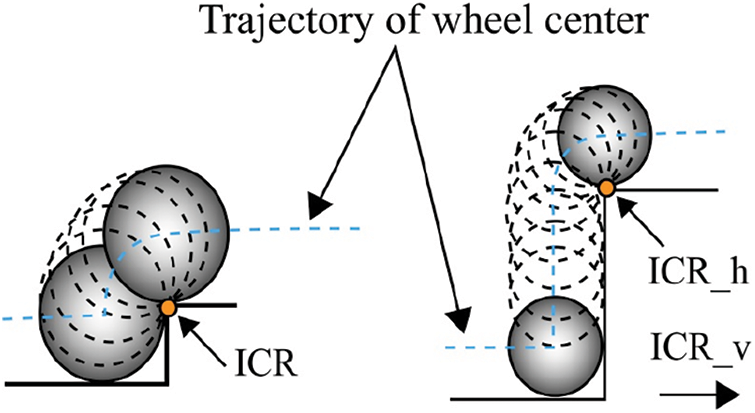
Figure 1: Wheel traversal (a) the wheel radius is equal to obstacle’ height (b) wheel radius is less than the height of the obstacle
Consequently, from the perspective of smooth-running, it is essential to study the variations of HPA quantitatively. Nevertheless, no appropriate measure for these constraints has been derived since the HPA variations are definitely impacted by many parameters including the type of links implemented, the number of lifted wheels, and the lifting height. Furthermore, as all interactions between lifted wheels and linkages of the robot cannot be taken into account in uneven environments, here lift-up of single wheel is considered to evaluate the traversability of the robot based on variations in HPA. The variables Δhi and Δθi represent the variations in HPA of the robot’s center-of-mass, when ith wheel is raised to a distance of di above the surface. For a wheeled product delivery robot, the variations in HPA of the robot are defined as
where
havg = variation in average height, hstd = standard deviation of variation in height, hmax = maximum height, θavg= average pitch angle variation, θstd = standard deviation of pitch angle variation and θmax = maximum pitch angle
The parameters x, y, and z are used to reflect the impact of each term properly because the robot mobility can be influenced by the numerical value of standard deviation and the maximum variation albeit the average HPA variation is minimum. Firstly, the fundamental assumptions are considered to assess the HPA variations more quantitatively. It is considered that the height of the lift up is the same as the wheel radius. As the radius is the greatest height of any obstacle, a product delivery robot can surmount without using a complex control system to step over the obstacles. Figs. 2a and 2b illustrate the 2D picture of the rocker-bogie’s suspension system and also the case where the front wheel is lifted, separately. In Fig. 2a, w, r, and h represent the distance between wheels, wheel radius, and the height of CM of the robot body from the ground, respectively.
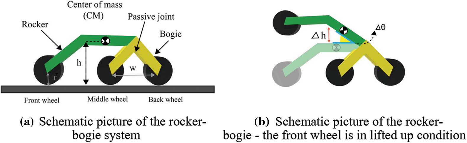
Figure 2: (a): Schematic picture of the rocker-bogie system, (b): Schematic picture of the rocker-bogie-the front wheel is in lifted up condition
3.2 The Proposed Rocker-Twin Bogies Suspension System
The product delivery robots with classic rocker-bogie mechanism must traverse at a very low speed to guarantee the balanced moving. In the supply chain system, mobile robots may face steps like obstacles to overcome. In this study, a structural adaptation to enlarge the span of classic rocker-bogie suspension mechanism to improve the traversability in retail shops is proposed. An experimental prototype with an additional set of wheels was developed to preserve continuous contact with the ground and to increase frictional force also. The driving mechanism of the new rocker-twin bogies suspension system consists of eight identical wheels, four steering gears, and one differential joint to connect the suspension subsystem with a payload platform, two bogies, two pendulum bars, and two connecting rods as shown in Fig. 3. The eight-wheeled rocker-twin bogies suspension guarantees that the product delivery robot can navigate over a height more than the height of the frame. This could extend about thrice the diameter of wheel.
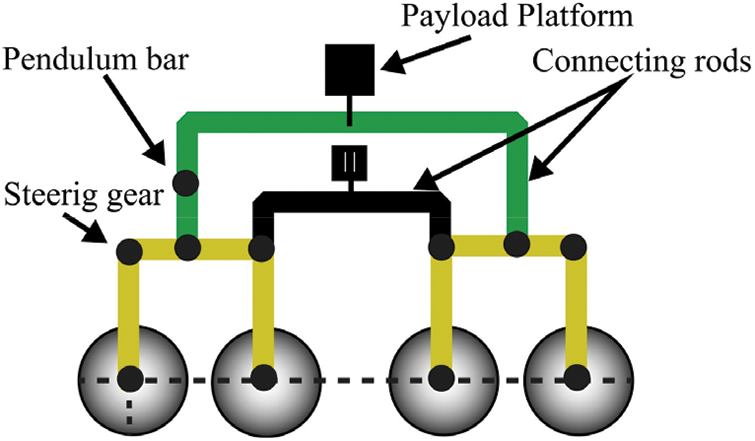
Figure 3: Schematic of the rocker-twin bogies suspension system
Furthermore, as the proposed suspension system is actuator-powered, the inclination of the robot can be adapted so that it does not collapse for a large range of slope and enables the robot to traverse over extremely rough surfaces such as steps or staircases. It supplies adequate traction force with the surface even in environments where there is a vertical drop or negative slope of about 1 m by means of a spring-damper system, and it realizes this without negotiating the strength of the body. The wheels, the linear actuator, four-bar linkage, and spring–damper arrangement provide support for the robot to navigate over obstacles.
3.3 Mobile Platform’s Kinematic Analysis
To assess the performance of a new suspension system to decrease the HPA variations during the stair-climbing process, the kinematic analysis on rugged terrain is performed. The layout of the proposed product delivery robot for kinematic analysis is given in Fig. 4. This study calculates the position, speed, and acceleration of the wheels and the global position of the robot using Euler angles values. Declared state variables are utilized to control the traction of the robot. A joint coordinate system is used to represent the correlation between robot balance and its active input [22].
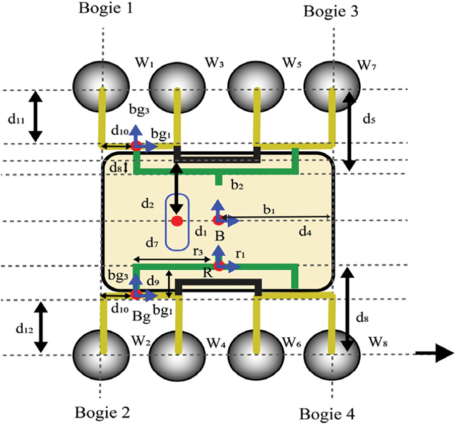
Figure 4: Kinematic model of the proposed suspension system
In the robot front axle, the velocity of wheels’ centers can be defined by the following Eq. (3)
Here j = 1, 2, j is the index. It corresponds to left front wheel and right front wheel.
where ωB is body spatial rotational velocity vector; Rx, Ry, and Rz are Euler angles’ rotational matrices: roll, pitch, and yaw.
where
4 Taguchi Method Based Optimization of Design Parameters
Taguchi method is an efficient parameter-design technique to select an optimum value for all parameters using simulation models or Design of Experiments (DoE) [23–25]. This technique finds those factors (independent variables) that have a substantial impact on the performance (dependent) variable by means of designed experiments. It is a convenient method to optimize designs to have high quality and high performance in fewer trials.
As stated earlier, the optimization goal is to change the CM trajectory to a straight line. As the slope of the staircase may differ based on its dimension, it is not rational to find the slope of a straight line. Hence, this optimization objective function is taken as minimization of the area in between CM’s trajectory and a straight line whose slope is just equal to slope of the staircase. The objective function gives equal importance to all sections of CM trajectory. The objective function of this optimization process, includes the straight line, the trajectory of CM, and the equivalent area. These are represented by a red line, a blue line, and a dotted blue line, correspondingly. The straight line’s origin is realized to be a posture of CM, where the front wheel’s moment retains contact with the staircase riser. The rover body’s CM considered in this work includes payloads except for wheels and links. The vehicle’s CM posture varies based on its position during traversing. So, with no generality loss during motion on a staircase, Rover’s CM is fixed to derive a kinematic relationship between wheels and links. In each simulation step, for a small known distance, the rover moves forward on the staircase. Hence, each wheel center’s trajectory is calculated logically from the wheels and links parameters.
In the Taguchi method, S/N ratio is used as the performance metric to calculate the quality of selected link parameters with noise factors. Maximization of the S/N ratio is the prime goal of this optimization. The random noise factors’ effect on the objective function is less when the S/N ratio is high. The goal of this optimization is to reduce the area in between CM’s trajectory and a straight line dictated by each staircase. The S/N ratio is calculated as
where, Yiis performance value of ith simulation, N is number of repetitions in the simulation process. In this work, since the optimization is achieved regarding three different stairs as given in Tab. 1, N denotes the no. of stairs and Yi represents the area in between the straight line calculated by the ith stair and the trajectory of CM. It is worth mentioning that maximization of the S/N ratio in Eq. (8) corresponds not only to diminish each area Yi but also to diminish the difference between them. Therefore, the equation of the S/N ratio (if N = 3) is rewritten as
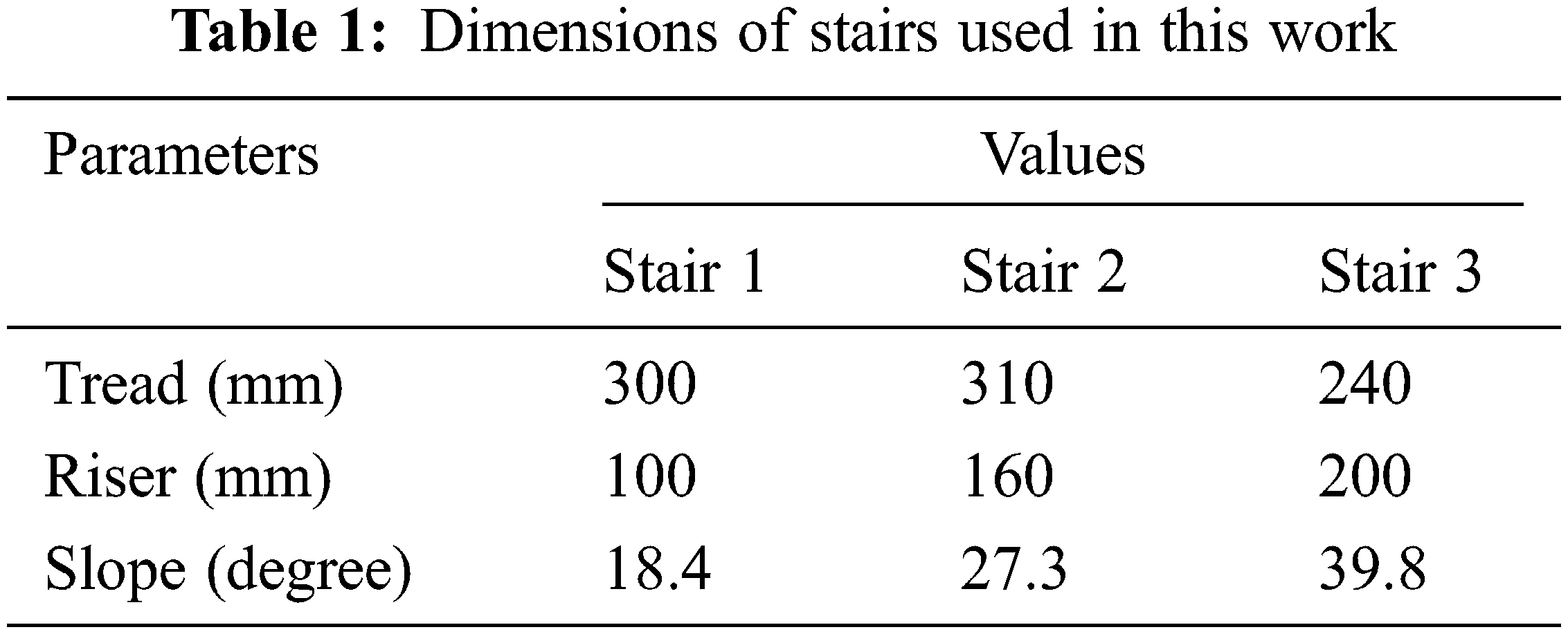
Three different stairs are considered in this study as user conditions. The main aim here is to find the design parameters that give the objective function’s minimum value for the considered types of staircases.
4.3 Parameters Influencing the System Performance
Design parameters are control factors of the system. It is required to find the parameters that affect the system performance. The robot’s successful climbing is the performance to study. Without getting overhung or jammed, the climbing of robots on the staircase is a successful activity. The effective climbing capacity of the robot is studied in this research work. Selecting suitable ranges for control factors is essential to exclude the unfeasible solution space. Different control factors with their choices are defined below:
Radius of Wheel (R): Wheels with a small radius make complications in the geometrical traffic ability of the vehicle. If the radius of the wheel is smaller than the size of overhangs then the average reaction force achieved from the overhang acts vertically downwards. If wheel radius is larger than the overhang size, this shifts the vertical downward normal force towards the robot’s axis of rotation. So, resultant contact force produces an anti-clockwise moment about the robot’s axis of rotation.
4.4 Design of Simulations by Means of Orthogonal Arrays
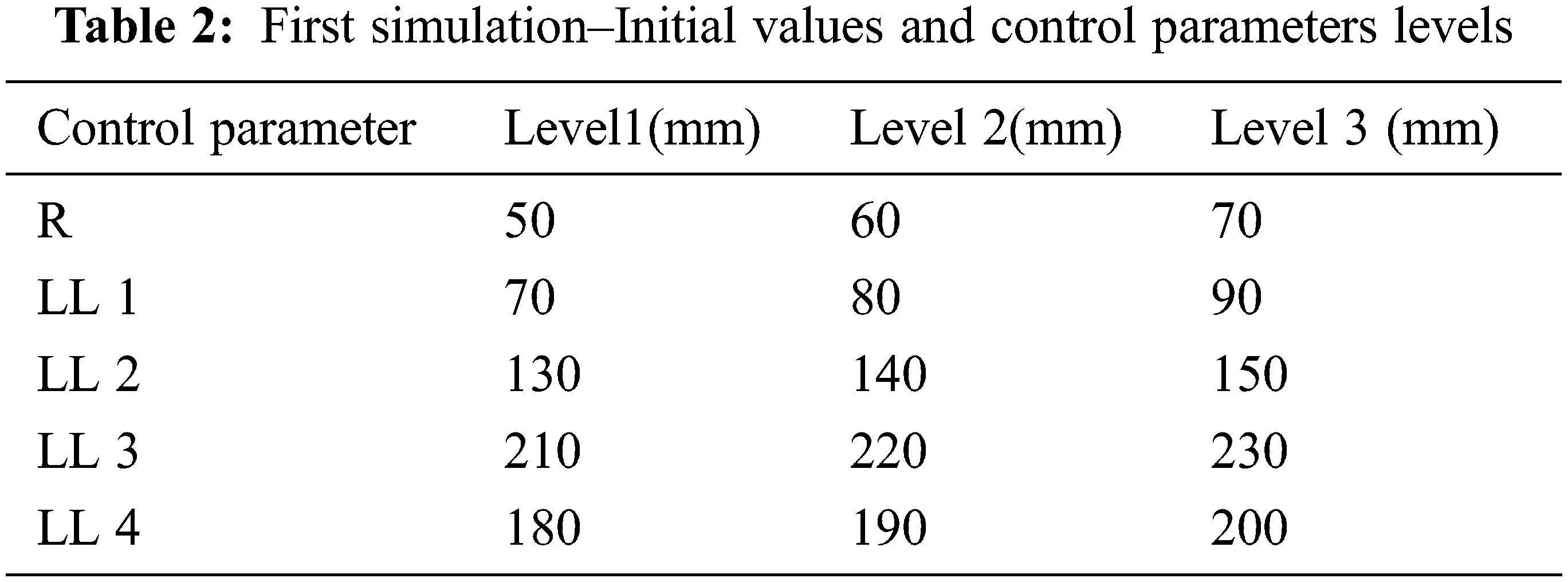
To begin the Taguchi optimization method, an initial analysis is conducted to estimate the region between three straight lines and the CM trajectory dictated by the suspension system’s predetermined design parameters. Lower and upper limitations apply to the wheel radius. Levels of control parameters and their primary values are given in Tab. 2.
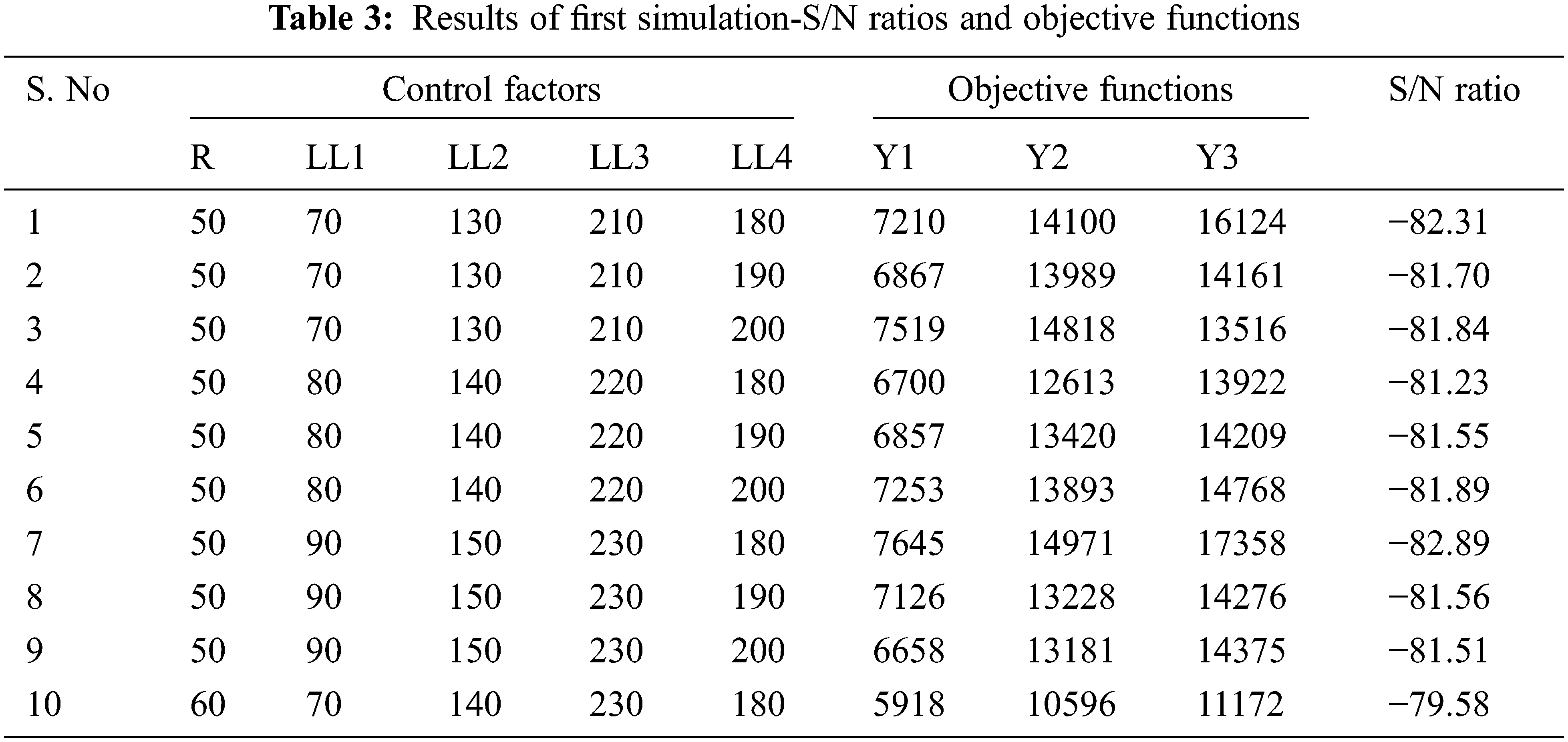
The Taguchi technique is used to optimise the link dimensions of the rocker-twin bogies system. The process begins with a sensitivity analysis of the S/N ratio. This is to ascertain all key control factors that contribute significantly to the derivation of the objective function. The optimization procedure is then repeated based on these essential control parameters in order to find the optimal values by appropriately espo using a new reduced OA. In Tab. 3, the resulting objective function (Yi), where ‘i’ = 1, 2, 3, and the accompanying S/N ratios are reported for each simulation from OA L27 (= 35). The average S/N ratios for each control factor are determined at various levels. This is to ascertain the fundamental effects of various control variables on the objective function. The level of the control factor is expressed by a superscript in the basic representation; for example, R3 shows that the level of control factor R is 3. It is demonstrated that R2,
It is critical to remember that the initial values of the control factors do not reveal kinematic restrictions. Because it is difficult to identify an ideal control factor composition that satisfies kinematic restrictions. Two constraints are violated by this combination of control factors (R2,
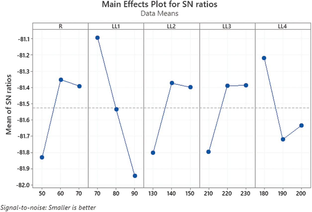
Figure 5: The first simulation - Average S/N ratios of the control factors
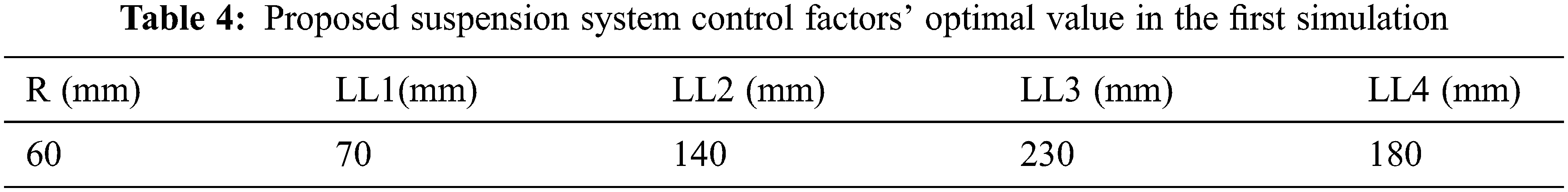
In the second simulation, to satisfy kinematic constraints combined with R2, larger values are selected for LL4 levels. Therefore, the S/N ratio is marginally improved from −79.58 dB to −79.38 dB for the revised composition of control factors as R1,
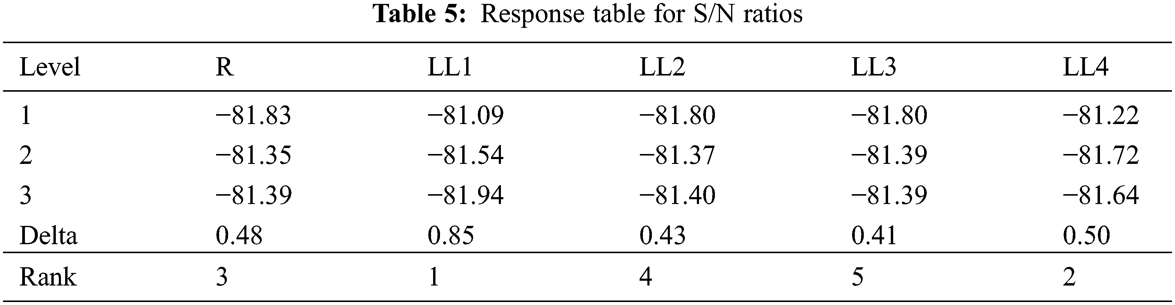
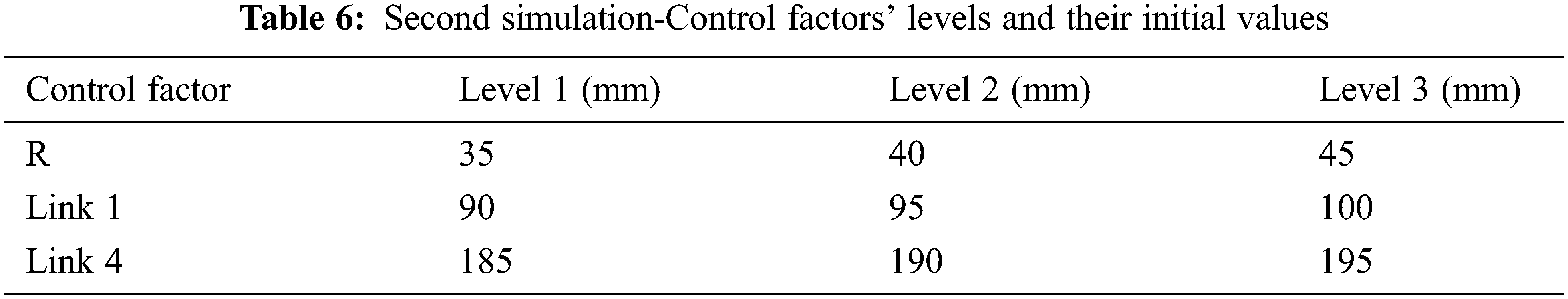
To find the factors with the maximum effect on average S/N ratios, the response table is derived as shown in Tab. 5. Based on these remarks, the other simulation concentrating on these parameters LL1, LL4 and R is carried out with the OA L9 (33) as given in Tab. 6. In the second simulation, for the reduced OA L9, S/N ratios, and objective function Yi. Except- LL1, LL4 and R, other factors are already estimated in the first simulation.
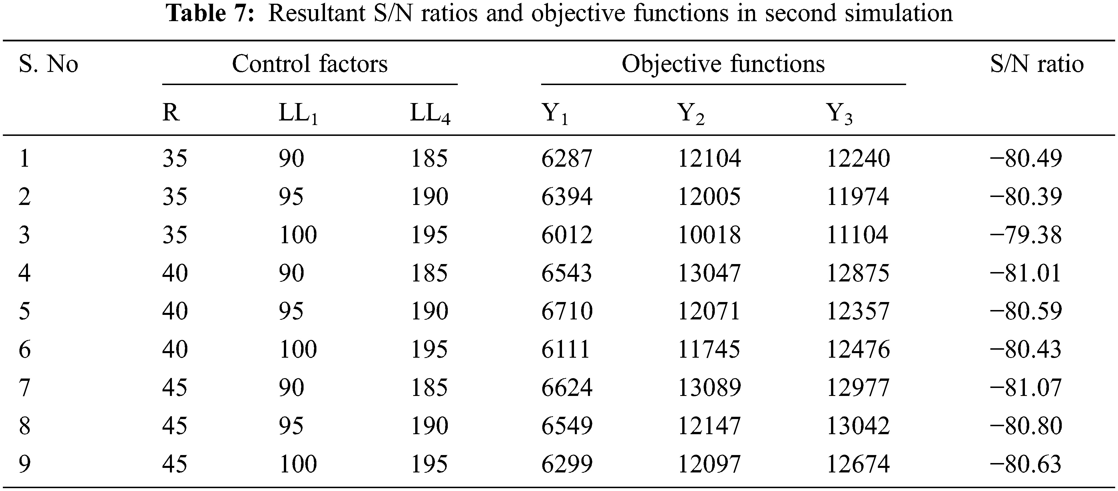
In the second simulation, optimum levels of LL1, LL4 and R are 3, 3, and 1 respectively. In comparison to the first simulation, S/N ratios are considerably enhanced higher than 1.5 dB. According to control factor ‘R’, the difference between the maximum and minimum average S/N ratios is below 0.1 dB. The optimal value of ‘R’ is 35 mm shown in Tab. 7. Kinematic constraints are satisfied by the resultant combination of (R1,
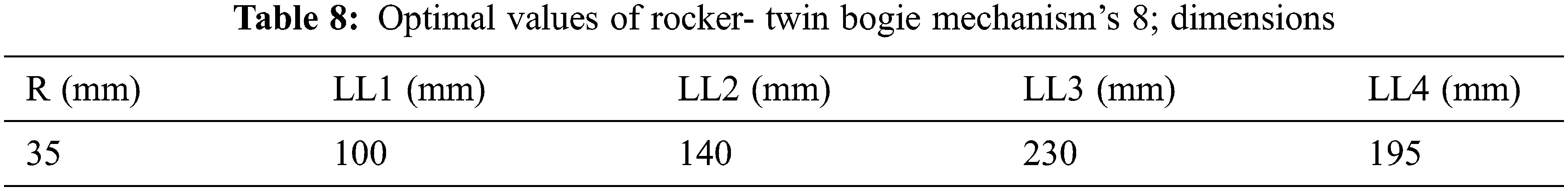
A critical point to remember is that the control factors will be optimised in successive simulations. OAL9 is still used since it is the smallest of the existing OAs for denoting two control elements at three levels. The control factor optimum values for the rocker-twin bogies system are reported in Tab. 8. With the goal of achieving a nearly straight line for the CM trajectory, the radius of the improved suspension system’s wheel naturally grows smaller.
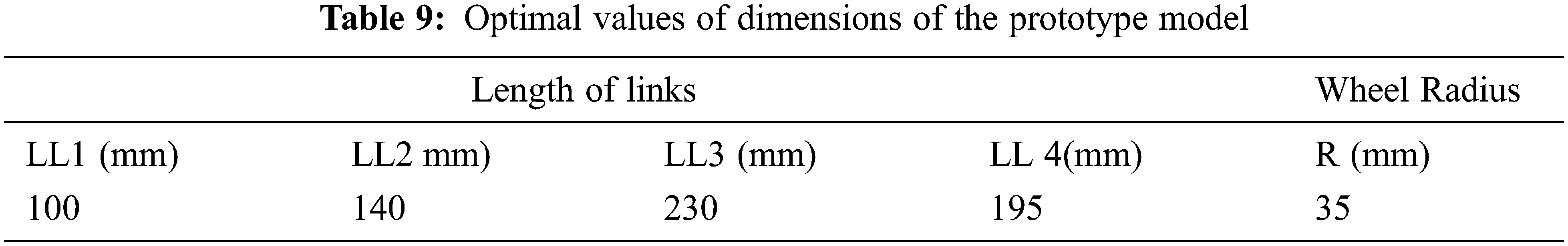
The key motivation of the proposed suspension system is to enable the product delivery robot to give traction for wheels to traverse in high stepped environment. Such a system enables the product delivery robot to travel properly in rugged environments which at present is a challenging endeavor for conventional robots in the supply chain system. In present designs, there is a restriction regarding the height of obstacles which robots can step over. It is very challenging for the conventional wheeled robots to climb up huge vertical obstacles. Using suspension systems with soft shocks, a robot could traverse staircases to an extent but regrettably, it cannot step over very high steps [26]. Therefore, there is a need for a novel and innovative suspension mechanism to drive robots against such obstacles. The snapshot of the developed model is shown in Fig. 6. To increase stair-climbing ability and thwart instability due to the wheel floating, the Taguchi optimization process was performed. The goal of the optimization is to achieve an effective stair-climbing process without losing the stability of the robot [27]. Based on results obtained from the Taguchi method, the diameter of wheels and the lengths of four links are optimally selected. The detailed dimensions of the prototype model of the product delivery robot are given in Tab. 9. The total weight and overall dimension of the product delivery robot are 6.5 kg and 405 mm × 340 mm × 220 mm (length × width × height), respectively.
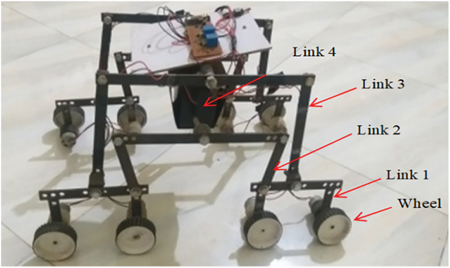
Figure 6: Prototype model of the proposed product delivery robot
A wall detecting sensor is used to accurately sense a contact condition during the climbing of stairs. The robot is powered by six high-power 12 V brushed DC motors with metal gears. Motor speed and torque are 180 RPM and 27 kg-cm respectively. The choice of rubber thread attached to the wheel makes it robust and lightweight. It produces excellent friction and traction. These plastic wheels provide a low-cost solution that is light enough to be practical yet still strong enough to operate in rugged terrain. In the prototype, a suitable wheel drive module to fix the wheel hubs inside was considered. It was attached to the steering module using a cantilevered link that aligns the steering axis via the wheel center. Optical encoders were utilized to know the velocity of wheel drive. Absolute magnetic encoders were utilized to know the wheel steer angles. A bogie joint and a rocker joint were attached to the rover chassis’ on both side. Also four steer-drive wheelsets using the links were connected to the rover chassis. With help of a differential mechanism, right-side and left-side suspension systems were joined. Items related to power, computing, communication, and motor controllers were placed in an electronics drive box. One ATMEL Mega 2560 microcontroller was used to do all onboard algorithms related to safety, wireless communication, power management, and driving. Additional software was also used by the microcontroller to enable data logging and debugging facility.
5.2 Experimental Setup and Results
The stair-climbing ability of the proposed system was evaluated with respect to more number of staircases with different widths and heights. The dimensions of stairs and time of traversal are logged for these tests and analysis was carried out to assess the efficiency of the product delivery rover. The objective of the proposed new suspension mechanism is to climb a staircase-like the obstacle of at least three times the wheel radius. The experiments conducted on different staircase dimensions on different surfaces namely wood; ceramic bricks, concrete, and carpet are given in Figs. 7–11. These experiments proved the proposed robot’s robustness under small changes in staircase dimensions. Snapshots of a robot climbing up 200 mm in height are given in Fig. 7. First, the front bogies climb on the obstacle (Figs. 7a and 7b), compressing its suspension spring. This discharges the rear bogie wheels’ load and so supports the bogie to step over (Figs. 7c–7e). The bogie gets a turn in the step’s upper corner when the wheel of the second bogie touches the wall. Now, the CM is extended to almost its maximum height. At the final point, the last wheel can ascent over on the step without any difficulty, pulled by the other wheels. Since the two bogies on each side are autonomous, even it is achievable to get on the staircase if the robot mechanism is not moving vertically or if one bogie hits an obstacle. Though it was intended to ascent steps up to 105 mm, the vehicle can ascent even steps of more than three times of its wheel radius (200 mm). Similar results are obtained while the robot is tested for climbing up 160 mm riser height, 310 mm tread, and 27.3° slope, as given in Fig. 8. Results are in the same line when the robot is tested for climbing up 100 mm riser height, 300 mm tread, and 18.4° slope, as given in Fig. 9. Similar results are obtained while the robot is tested for climbing up 200 mm riser height, 240 mm tread, and 39.8° slope, as given in Fig. 10. Similar results are obtained while the robot is tested for climbing up 100 mm riser height, 300 mm tread, and 18.4° slope, as given in Fig. 11.
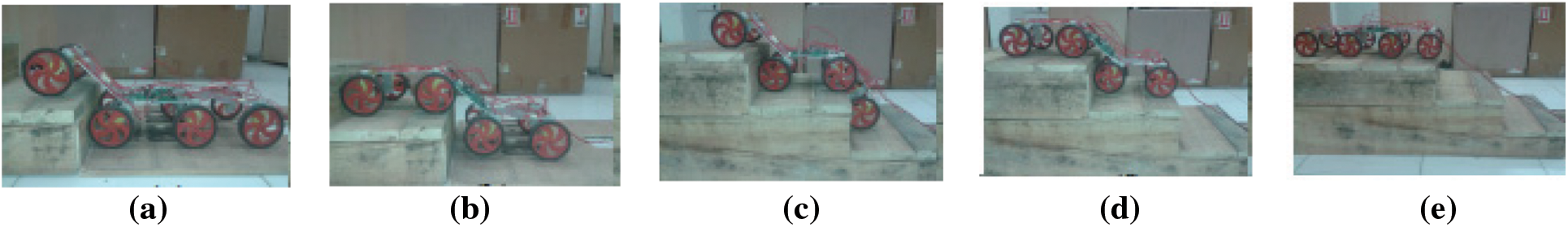
Figure 7: The robot is climbing on wooden staircases with dimensions as 200 mm riser, 240 mm tread and 39.8° slope
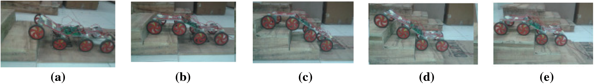
Figure 8: The robot is climbing on wooden staircases with dimensions as 160 mm riser, 310 mm tread and 27.3° slope
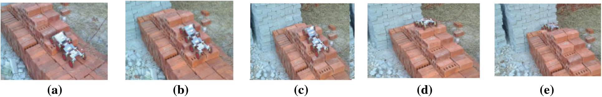
Figure 9: The robot is climbing on brick staircases with dimensions as 100 mm riser, 300 mm tread and 18.4° slope
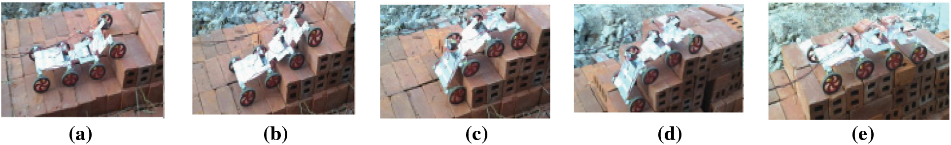
Figure 10: The robot is climbing on brick staircases with dimensions as 200 mm riser, 240 mm tread and 39.8° slope
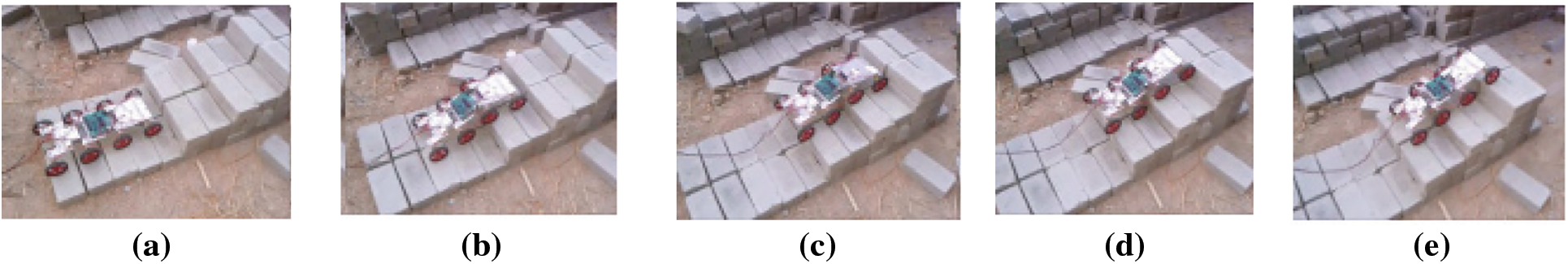
Figure 11: The robot is climbing on concrete staircases with dimensions as 100 mm riser, 300 mm tread and 18.4° slope
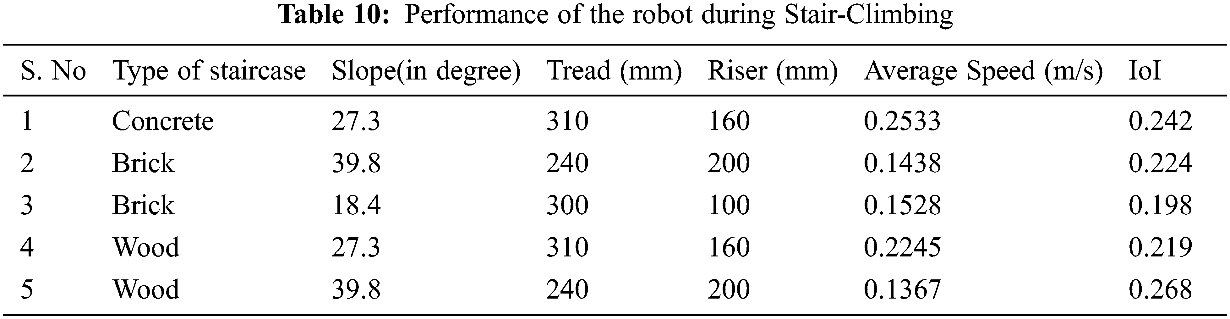
The speed and IoI of the proposed system are measured while traveling on the rugged terrain. As the value of IoI depends on variation in HPA of the body, a traversal with a low IoI value can be anticipated to demonstrate low HPA variations while traveling in the uneven environment, which ensures smooth movement of the CM shown in Tab. 10.
6 Conclusions and Recommendations
Based on an eminent rocker-bogie mechanism design, this work proposes an optimal design of product delivery wheeled robots in the supply chain system in order to guarantee higher stability and outstanding adaptability during climbing staircases. In the proposed system, the front wheel of the conventional rocker-bogie system is replaced with one more bogie arrangement. The proposed novel eight-wheeled robot with rocker-twin bogies suspension can achieve increased stability and climb over heights more than the chassis height (i.e., 3 times as far as the radius of wheels). The design parameters of the proposed product delivery robot are optimized to get a smooth trajectory for the vehicle’s center-of-mass using the Taguchi method. A new performance measure known as the Index of Instability (IoI) is introduced to assess the smooth running of the robot against a step or staircase. IoI is used to predict unwanted swinging while the robot stepping over the obstacles. This work exhaustively analyzed the traversability of different robots based on IoI metric. Finally, the kinematic analysis is done to demonstrate the traversability of the proposed system over vertical obstacles as related to renowned mobile robots in the literature. The results reveal that the modified rocker-bogie system not only increases stair-climbing capability but also thwarts instability due to overturning of a wheel of the robot. Hence a bright future for staircase robots is available in supply chain industries. Especially for delivering goods to customers can be effectively done by these robots. Visibility of end-to-end delivering goods, automation, and control of order taking and delivery are good using these robots. The advantages of using supply-chain robots are reduced errors, timely delivery, getting timely information, increased trust, efficiency in all working environments, etc. Robots are very reliable for automating both internal and external activities of the supply chain. Suppliers, logistics industries, and customers can rely on the output of supply-chain robots. The performance of the robot during stair climbing is experimentally tested based on the material of the staircase and the degree of slope. Concrete, brick, and wood are the materials considered for the analysis. Different degrees of slope considered here are 27.3, 39.8, and 18.4. For the concrete material with the degree of slope 27.3, the average speed and IoI obtained are 0.2533 and 0.242, respectively. For the wood material with the degree of slope 27.3, the average speed and IoI obtained are 0.2245 and 0.219, respectively. From the above discussed two scenarios, it is seen that when in the degree of slope 27.3 the best average speed is obtained. For the wood material with the degree of slope 39.8, the average speed and IoI obtained is 0.1367 and 0.268, respectively. From the above discussed scenarios, it is seen that the proposed model gives it best with the concrete material and 27.3 degrees of slope.
Funding Statement: The authors received no specific funding for this study.
Conflicts of Interest: The authors declare that they have no conflicts of interest to report regarding the present study.
1. V. V. Battua, R. J. M. Ventayenb, A. Firosc and R. Yadav, “Unmanned six-wheel bogie rover with robotic arm for surveillance and fixing objects,” Turkish Journal of Computer and Mathematics Education, vol. 12, no. 10, pp. 2066–2075, 2021. [Google Scholar]
2. F. A. Hamim, I. A. Probal, A. S. Ahmed, M. A. Islam and M. A. B. Siddik, “An enhanced prototype of rover for space exploration,” Advances in Astronautics Science and Technology, vol. 3, no. 1, pp. 75–96, 2020. [Google Scholar]
3. U. Illahi and M. S. Mirf, “Maintaining efficient logistics and supply chain management operations during and after coronavirus (COVID-19) pandemic: Learning from the past experiences,” Environment, Development and Sustainability, vol. 12, pp. 1–22, 2021. [Google Scholar]
4. J. Liu, L. Xu, S. Chen, H. Xu, G. Cheng et al., “Development of a bio-inspired wall-climbing robot composed of spine wheels, adhesive belts and eddy suction cup,” Robotica, vol. 39, no. 1, pp. 3–22, 2021. [Google Scholar]
5. K. Mathiyazhagan, S. Nangia, A. Senthilkumar, K. Elangovan, K. Savita et al., “Modelling the interrelationship of risks for green supply chain management adoption: A DEMATEL approach,” International Journal of Logistics Systems and Management, vol. 30, no. 3, pp. 414–440, 2020. [Google Scholar]
6. S. Qu, H. Yang and Y. Ji, “Low-carbon supply chain optimization considering warranty period and carbon emission reduction level under cap-and-trade regulation,” Environment, Development and Sustainability, vol. 36, pp. 1–28, 2021. [Google Scholar]
7. A. Yıldızbaşi, C. Ozturk, D. Efendioglu and S. Bulkan, “Assessing the social sustainable supply chain indicators using an integrated fuzzy multi-criteria decision-making methods: A case study of Turkey,” Environment, Development and Sustainability, vol. 23, pp. 4285–4320, 2021. [Google Scholar]
8. Z. Li, C. Deng and K. Zhao, “Human-cooperative control of a wearable walking exoskeleton for enhancing climbing stair activities,” IEEE Transactions on Industrial Electronics, vol. 67, no. 4, pp. 3086–3095, 2020. [Google Scholar]
9. V. Sathiya, M. Chinnadurai, S. Ramabalan and A. Appolloni, “Mobile robots and evolutionary optimization algorithms for green supply chain management in a used-car resale company,” Environment, Development and Sustainability, vol. 23, pp. 9110–9138, 2021. [Google Scholar]
10. D. Hanafi, A. Rahman and K. Azlan, “The mobile robot development for air pollution tele data capture,” Journal TeknologiElektro, Universitas MercuBuana, vol. 7, no. 2, pp. 95–100, 2016. [Google Scholar]
11. M. Gonzalez-de-Soto, L. Emmi., C. Benavides and I. García, “Reducing air pollution with hybrid-powered robotic tractors for precision agriculture,” Biosystems Engineering, vol. 143, pp. 79–94, 2016. [Google Scholar]
12. R. Saada, “Green transportation in green supply chain management,” in Green Supply Chain, First Edition, Intech Open Press, London, 2020. [Google Scholar]
13. G. T. Aguiar, G. A. Oliveira, K. H. Tan, N. Kazantsev and D. Setti, “Sustainable implementation success factors of AGVs in the Brazilian industry supply chain management,” Procedia Manufacturing, vol. 39, pp. 1577–1586, 2019. [Google Scholar]
14. H. Jiang, G. Xu, W. Zeng and F. Gao, “Design and kinematic modelling of a passively-actively transformable mobile robot,” Mechanism and Machine Theory, vol. 142, pp. 103591–103612, 2019. [Google Scholar]
15. B. D. Harrington and C. J. Voorhees, “The challenges of designing the rocker-bogie suspension for the Mars exploration rover,” in the Proc. of Aerospace Mechanisms Symp., Jet Propulsion Laboratory, California Institute of Technology, Pasadena, CA, US, pp. 19–21, 2004. [Google Scholar]
16. V. G. Yadav, T. Kazmi and K. Harshith, “Augmented reality tourism using tele-rover,” in Proc. of 7th Int. Conf. on Computing for Sustainable Global Development (INDIACom), New Delhi, India, pp. 124–129, 2020. [Google Scholar]
17. C. Visconte, P. Cavallone, L. Carbonari, A. Botta and G. Quaglia, “Design of a mechanism with embedded suspension to reconfigure the agri_Q locomotion layout,” Robotics, vol. 10, no. 1, pp. 15, 2021. [Google Scholar]
18. I. A. Probal, F. A. Hamim, M. A. Islam and M. A. B. Siddik, “Mars rover and its strategic implementation,” in Proc. of Int. Conf. on Information and Communication Technology for Sustainable Development (ICICT4SD), Dhaka, Bangladesh, pp. 215–219, 2021. [Google Scholar]
19. F. Ullrich, A. Haydar and G. S. Sukkarieh, “Design optimization of a Mars rovers rocker-bogie mechanism using genetic algorithms,” in Proc. of 10th Australian Space Science Conf., Brisbane, Australia, pp. 199–210, 2011. [Google Scholar]
20. R. A. Lindemann and C. J. Voorhees, “Mars exploration rover mobility assembly design, test and performance,” in Proc. IEEE Int. Conf. on Systems, Man and Cybernetics, Waikoloa, HI, USA, vol. 1, 2005. [Google Scholar]
21. S. Ryu, Y. Lee and T. Seo, “Shape-morphing wheel design and analysis for step climbing in high speed locomotion,” IEEE Robotics and Automation Letters, vol. 5, no. 2, pp. 1977–1982, 2020. [Google Scholar]
22. A. J. R. Lopez-Arreguin and S. Montenegro, “Improving limitations of rover missions in the moon and planets by unifying vehicle–terrain interaction models,” Advances in Astronautics Science and Technology, vol. 3, no. 1, pp. 17–28, 2020. [Google Scholar]
23. B. K. Rout and R. K. Mittal, “Parametric design optimization of 2-dof R–R planar manipulator—A design of experiment approach,” Robotics and Computer-Integrated Manufacturing, vol. 24, no. 2, pp. 239–248, 2008. [Google Scholar]
24. H. Kim, D. Kim, H. Yang, K. Lee, K. Seo et al., “Development of a wall-climbing robot using a tracked wheel mechanism,” Journal of Mechanical Science and Technology, vol. 22, no. 8, pp. 1490–1498, 2008. [Google Scholar]
25. K. Lee and J. Kim, “Controller gain tuning of a simultaneous multi-axis PID control system using the taguchi method,” Control Engineering Practice, vol. 8, no. 8, pp. 949–958, 2000. [Google Scholar]
26. J. A. Shivam Kumar, P. Subramaniam, L. Mercy and S. D. Raj, “Design and fabrication of smart rover using rocker bogie mechanism,” AIP Conference Proceedings, vol. 2311, no. 050003, pp. 1–15, 2020. [Google Scholar]
27. K. Kim, Y. Kim, J. Kim, H. S. Kim and T. Seo, “Optimal trajectory planning for 2-DOF adaptive transformable wheel,” IEEE Access, vol. 8, pp. 14452–14459, 2020. [Google Scholar]
 | This work is licensed under a Creative Commons Attribution 4.0 International License, which permits unrestricted use, distribution, and reproduction in any medium, provided the original work is properly cited. |