DOI:10.32604/iasc.2023.025511
| Intelligent Automation & Soft Computing DOI:10.32604/iasc.2023.025511 | |
| Article |
Fuzzy Based Interleaved Step-up Converter for Electric Vehicle
School of Electrical Engineering, Vellore Institute of Technology, Vellore, 632014, India
*Corresponding Author: R. Saravana kumar. Email: rsaravanakumar@vit.ac.in
Received: 26 November 2021; Accepted: 10 March 2022
Abstract: This work focuses on the fuzzy controller for the proposed three-phase interleaved Step-up converter (ISC). The fuzzy controller for the proposed ISC converters for electric vehicles has been discussed in detail. The proposed ISC direct current (DC-DC) converter could also be used in automobiles, satellites, industries, and propulsion. To enhance voltage gain, the proposed ISC Converter combines boost converter and interleaved converter (IC). This design also reduces the number of switches. As a result, ISC converter switching losses are reduced. The proposed ISC Converter topology can produce a 143 V output voltage and 1 kW of power. Due to the high voltage gain of this converter design, it is suitable for medium and high-power systems. The proposed ISC Converter topology is simulated in MATLAB/Simulink. The simulated output displays a high output voltage. But the output voltage contains maximum ripples. Fuzzy proposes an ISC Converter which makes closed loop responsiveness and reduces the output voltage ripple. The proposed ISC converter has the lowest ripple output voltage, which is less than 2%, because the duty cycle is regulated using the fuzzy logic controller. It offers high voltage gain, minimal ripple, and low switching loss. The performance of the proposed converter is compared to that of the fuzzy and Proportional Integral (PI) controllers implemented in MATLAB.
Keywords: Step-up converter; interleaved converter; ripple voltage; fuzzy; electric vehicles
The scarcity of fossil fuels and the rising threat of global warming have recently emerged as major worldwide concerns. Electric vehicles (EV) are the most reliable and practical solution for complying with increasingly strict environmental standards. The vast majority of these vehicles are equipped with battery packs that can be used to power electric automobiles [1]. In modern EV chargers, power control components such as DC-DC converters, which provide a direct current link between the battery and the inverter circuit, are included [2,3]. In the automotive, aerospace, industrial, and propulsion industries, the three-phase Interleaved Step-up DC-DC Converter (ISC) is well suited for battery applications. In order to store the energy required to provide the necessary torque and speed, electric cars are equipped with large-capacity batteries [4]. Topologies of DC-DC converters for electric vehicles include the Boost Converter, Buck Converter, Interleaved Converter, and others [5,6]. Because of the downsizing capabilities of battery packs, they are frequently used in a variety of applications.
A three-phase Interleaved Step-up DC-DC Converter based on the fuzzy architecture has been presented. In addition, this converter has the capability of operating in a Step-up mode. Electric vehicle propulsion systems require a high input voltage to function properly. As a result, the output voltage ripple, voltage stress, voltage gain, and efficiency are all reduced [7–9], and the voltage gain and efficiency are all raised. The most active research field in industrial and automation is fuzzy logic control (FLC). Unlike other control methods, FLC works best on complex, ill-defined issues that can be controlled by human experts. As a result, it provides a system with a double advantage. In addition to lowering the total cost, fuzzy enhances voltage regulation while simultaneously reducing complexity [10,11]. By modifying the duty cycle of the proposed ISC Converter, fuzzy was used to regulate the output voltage ripple and reduce the losses of the proposed ISC Converter. Consequently, it has a higher level of precision and efficiency. The current topology of the interleaved converter is quite similar to that of a single-phase boost converter, which has been utilized in electric vehicles in the past. Once the battery packs have been decreased, the rated voltage [12–14] will be reduced as well. Due to a lack of capability, the single-phase interleaved converter is incapable of supplying sufficient voltage to the transmission system (electric motor) due to a lack of capability [15,16]. Among the topology’s features is the incorporation of a three-phase interleaved boost converter, which assists in the downsizing of battery packs while also supplying sufficient voltage to the electric motor [17].
3 Proposed Three Phase Interleaved Step-up DC-DC Converter and Modes of Operation
The block diagram of fuzzy based converter is shown in Fig. 1. A high step up is therefore conceivable with the suggested ISC Converter topology, as illustrated in Fig. 2. A three-winding transformer between two phases is combined with a five-winding transformer as a result of the overall design of the converter topology, which results in a total of five winding transformers. The high Step-up operation creates a high output voltage that supplies propulsion to the motor while also overcoming the back emf of the driving circuit. The battery is directly connected to the inductor windings (L1, L2, and L3) through the use of a direct connection cable. The proposed converter circuit contains six diodes (D1 to D6) and central inductor windings (LC1 and LC2) are connected to the cathodes of the diodes D1, D2, and D3 and the anodes of the diodes D4, D5, and D6 through the central windings LC1 and LC2 respectively. An additional component of the ISC converter is a set of three power semiconductor switches (S1, S2, and S3), as well as an output capacitor (C) that is attached across the load resistance (R). Also connected across the switches is a freewheeling diode, which allows for freewheeling of the leakage current passing through the switches. The structure of ISC is depicted in Fig. 2. Eight modes of operation for the proposed ISC Converter will be described below using Fig. 3.
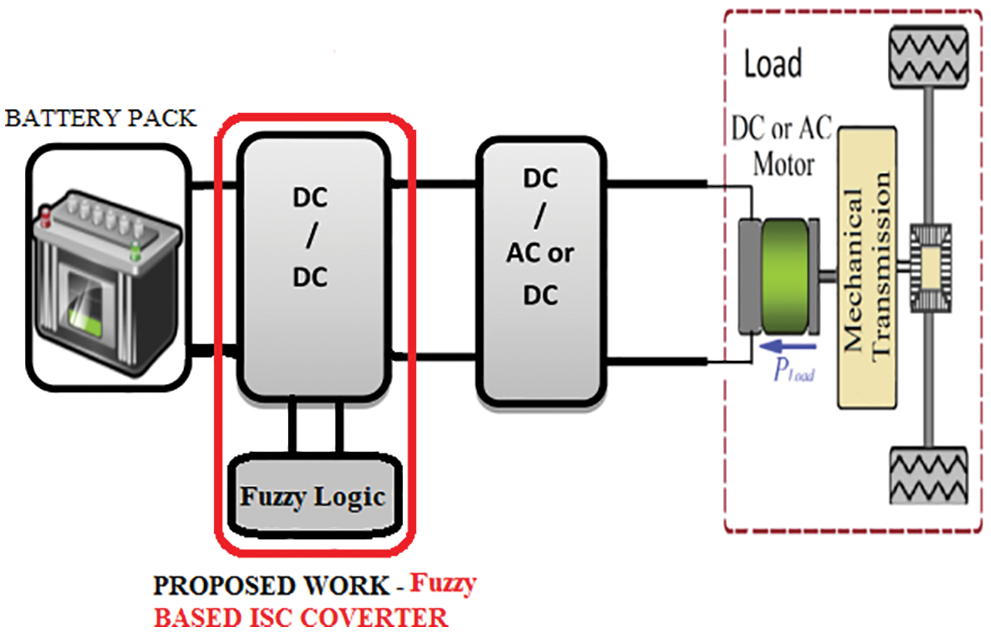
Figure 1: Block diagram of proposed fuzzy based ISC converter
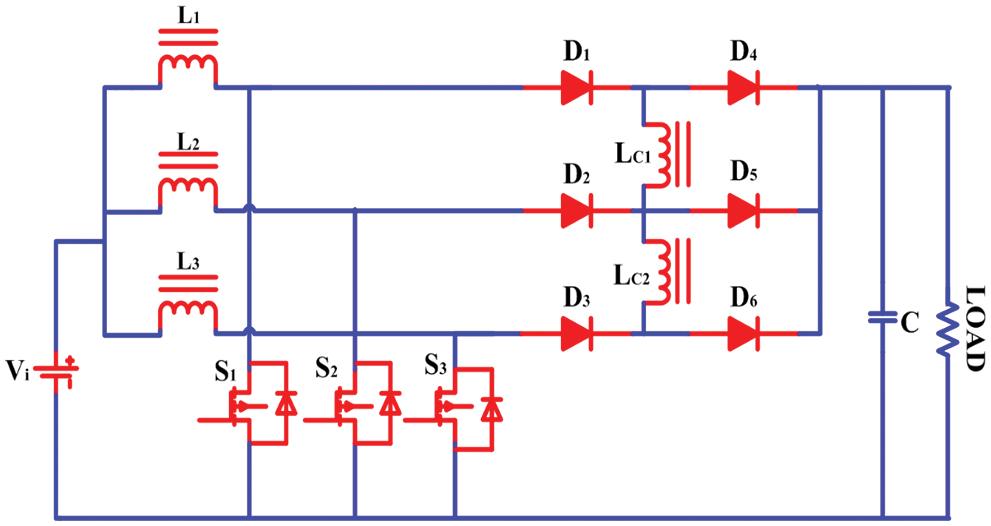
Figure 2: Proposed three phase interleaved Step-up DC-DC converter [ISC]
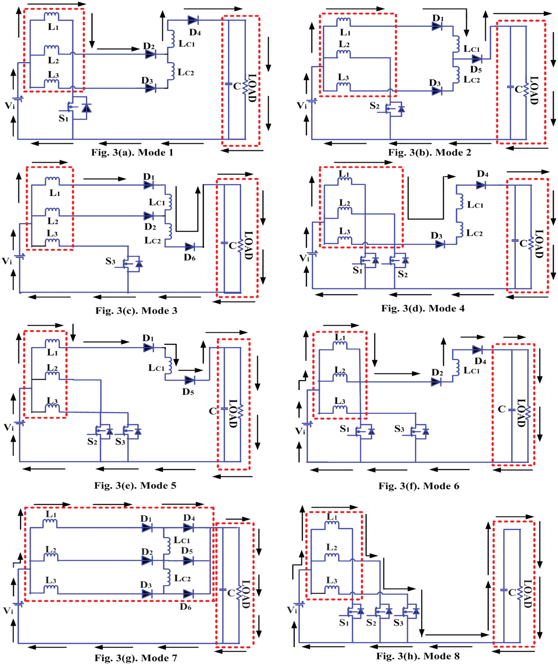
Figure 3: Modes of operation
Mode 1: Switch S1 is firstly switched on, while switches S2 and S3 are turned off, as shown in Fig. 3a. The battery’s current passes through the L1 winding and switch S1. L2 and L3 are likewise carried by the battery current. L2 transfers current to D2, LC1, D4, C, and the load. L3 transfers current to D3, LC2, LC1, D4, C, and the load.
Mode 2: Switch S2 is firstly turned on, whereas S1 and S3 are turned off, as shown in Fig. 3b. Through the winding L2, current from the battery reaches the switch S2. L1 and L3 are both supplied by the battery current. L1 transfers current to D1, LC1, D5, C, and the load. L3 transfers current to D3, LC2, D5, C, and the load.
Mode 3: Switch S3 is turned on, whereas S1 and S2 are turned off, as shown in Fig. 3c. The battery’s current travels through the L3 winding and the S3 switch. L1 and L2 are also connected to the battery current. D1, LC1, LC2, D6, C, and the load all receive current through L1. D2, LC2, D6, C, and the load all receive current through L2.
Mode 4: The switches S1 and S2 are initially turned on, as shown in Fig. 3d, while S3 is turned off. The battery’s current passes through the winding L1 and switch S1, as well as the winding L2 and switch S2. L3, D3, LC2, LC1, D4, C, and the load are all supplied by the battery current.
Mode 5: The switches S2 and S3 are initially turned on, while S1 is switched off, as shown in Fig. 3e. The battery’s current passes through the winding L2 and switch S2, as well as the winding L3 and switch S3. L1, D1, LC1, D5, C, and the load are all powered by the battery current.
Mode 6: S1 and S3 are initially switched on, whereas S2 is turned off, shown in Fig. 3f. The battery’s current passes through the winding L1 and switch S1, as well as the winding L3 and switch S3. L2, D2, LC1, D4, C, and the load are all connected to the battery current.
Mode 7: As shown in Fig. 3g, all three switches S1, S2, and S3 are kept off. The current from the battery powers the L1, L2, and L3 windings. The current from the battery travels through the L1 to D1, D4, C, and the load. D2, D5, C, and the load are all powered by L2 current. D3, D6, C, and the load are all powered through L3.
Mode 8: All three switches S1, S2, and S3 are switched on, as shown in Fig. 3h. Current flows through the L1 and S1 windings, as well as the L2 and S2 windings, and the L3 and S3 windings. The capacitor C is also discharged into the load.
The inductor’s current ripples (ΔiLn)
Value of inductor (Ln) is calculated by
The maximum voltage ripple (ΔV) over the capacitance-voltage relationship
Value of capacitor (C) is calculated by
The voltage gain (M) is the ratio of output voltage (Vo) to input voltage (Vi) can be calculated using the equation
The switch’s voltage stresses (Vs) and diode’s voltage stresses (Vd) are represented as
where, f is the frequency and N is the number of turns in the inductors.
4 Fuzzy Logic Control Design and Operation
In recent years, there has been a great deal of interest in fuzzy management in DC-DC converters, mostly because of its ability to improve dynamic performance and provide the needed outputs [18–20]. In this work, Sugeno’s fuzzy inference method serves as the foundation for the control of DC-DC converters. Its ability to process a large amount of data while also responding to various fault scenarios for changes in inputs while operating in real-time settings is one of its many advantages [21,22]. The operating waveforms of switches is shown in Fig. 4.
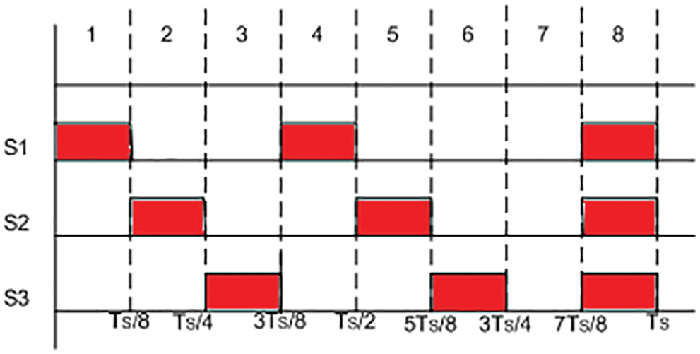
Figure 4: Operating waveform of duty cycle (D) = Ts/8
Specifically, the fuzzy controller uses the error signal and its rate of change to determine the required rate of change in the plant’s output feedback [23]. Fig. 5 depicts the block diagram of the fuzzy system, which is composed of four components: fuzzification, rule-base, inference mechanism, and defuzzification. Using the fuzzification interface, the inputs are classified into the relevant categories, such as Error (E) and Change in Error (CE). The rule-base is made up of fuzzy sets (database) and fuzzy control rules [24,25].
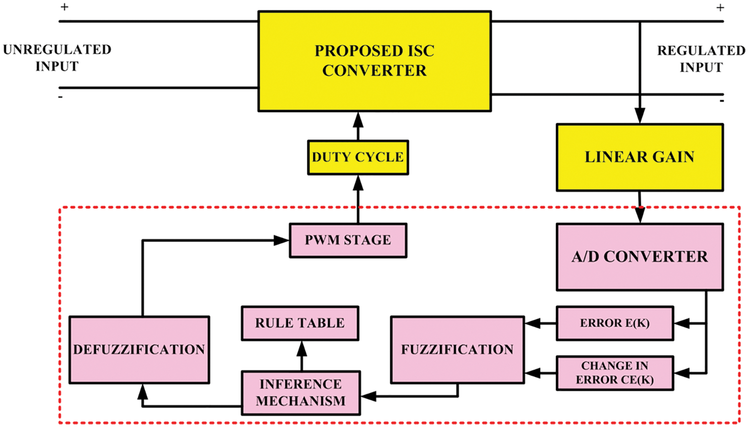
Figure 5: Basic component of fuzzy
By employing fuzzy relations and inference rules, the inference mechanism can replicate human decision-making based on fuzzy ideas as well as infer fuzzy control actions from fuzzy concepts. As shown in Fig. 5, When the defuzzification stage is completed, it extracts findings from the inference mechanism and generates an output that is then fed back into the pulse width modulation (PWM) stage, which adjusts the duty cycle of the proposed ISC converter [26,27].
As illustrated in Fig. 6, digital data is transformed from the output of the proposed ISC Converter, namely, error (E) and change in error (CE). Fuzzification is a process that involves comparing the suggested converter output value to a reference value. The various values of error (E) and change in error (CE) are transformed into an error membership function that has a range of 0 to 1 point. Fig. 7 shows a representation of the membership function for error, while Fig. 8 depicts a representation of the membership function for change in error.
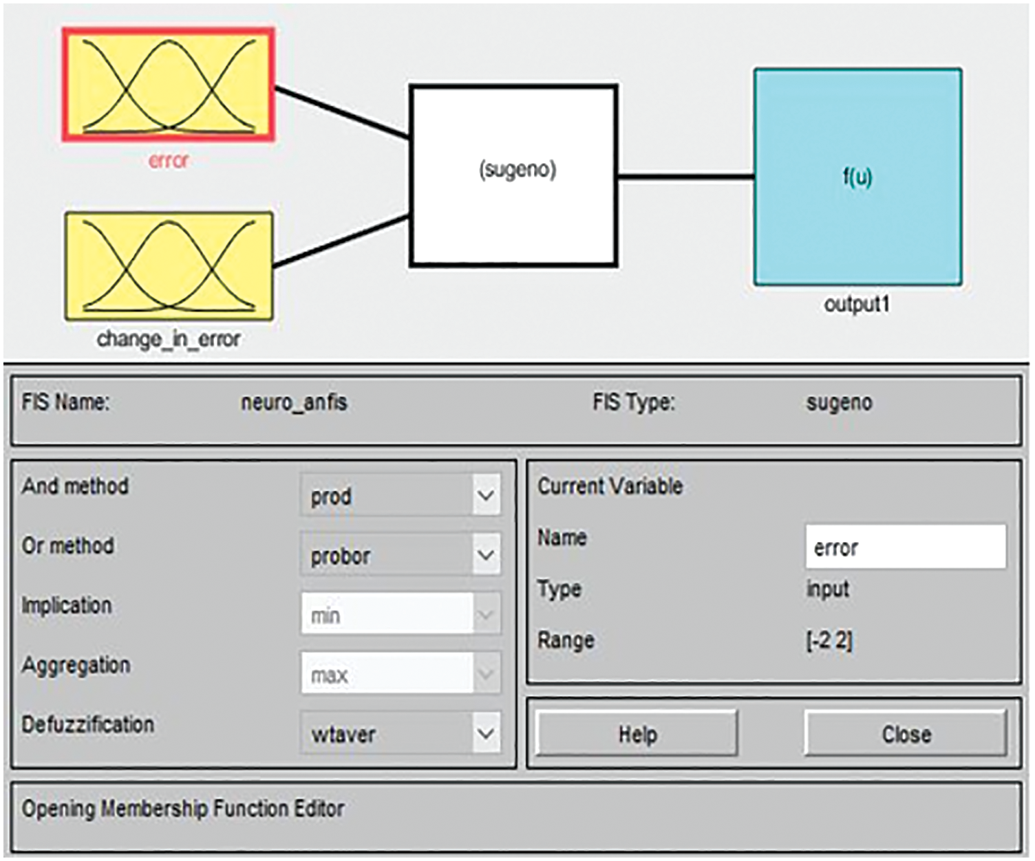
Figure 6: Block of fuzzy (sugeno)
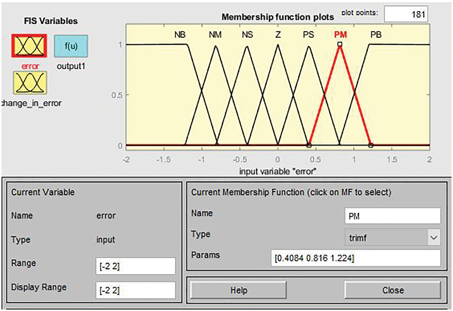
Figure 7: Error membership function
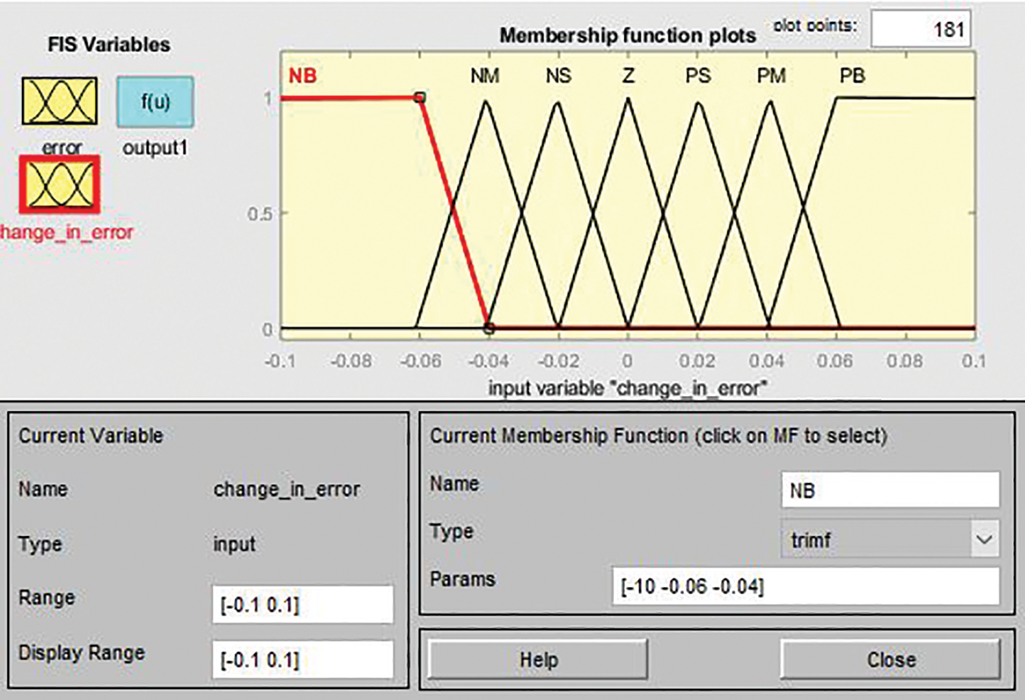
Figure 8: Change in error membership function
A rule base is a collection of distinct sorts of rules that are grouped together. Fuzzy logic algorithms are often composed of “if and then” criteria that must be met in order to function. A condition is represented by the preposition "if," while a conclusion is denoted by the preposition "then." This is illustrated in Fig. 9, where the controller implements these concepts and delivers the appropriate signal to the plant based on the received input data, such as error (E) and change in error (CE). If the load voltage of the converter is greater than the required value, the duty cycle should be lowered to compensate. If the load voltage of the converter is less than the reference voltage, the duty cycle should be increased. Generally, the inference mechanism is a decision-making process that generates a control signal that is supplied to the plant under a variety of operating circumstances. Defuzzification is the inverse of fuzzification in terms of its effect. It integrates all of the judgements made into a single crisp value that is sent into the proposed ISC converter through the PWM generator, which regulates the output voltage by adjusting the duty cycle of the PWM generator, which is depicted in the flowchart shown in Fig. 10.
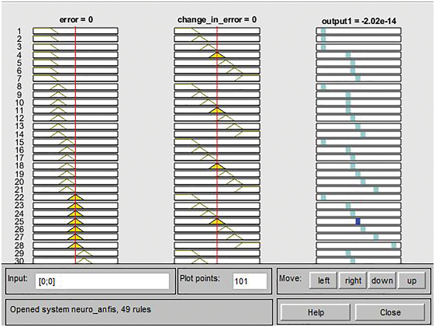
Figure 9: Fuzzy rule base
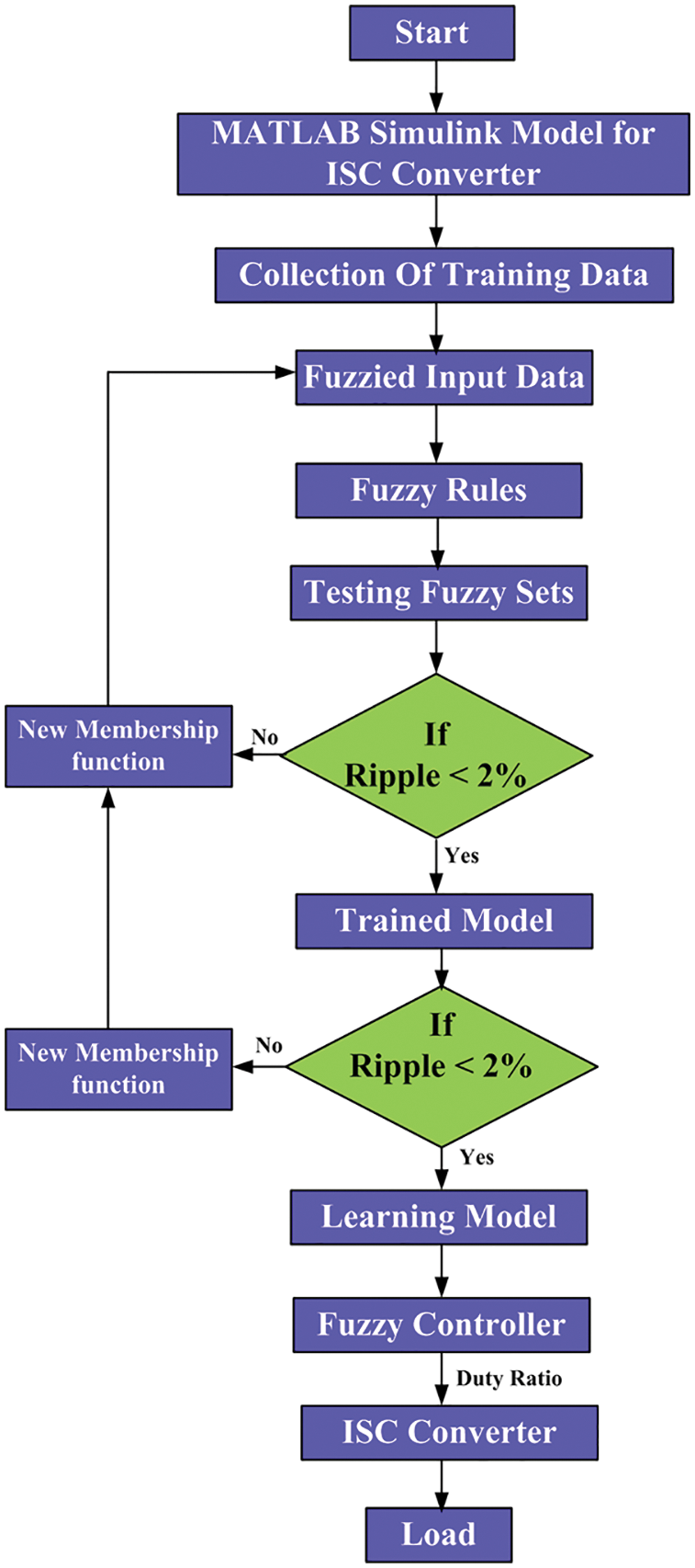
Figure 10: Flow chart of fuzzy based ISC converter
Fig. 2 depicts a three-phase interleaved Step-up DC-DC converter that has been developed. The proposed ISC converter, both with and without fuzzy, was simulated using MATLAB. [24] It provides the essential rules for simulating the topology of the converter. The magnitudes of the parameters that were utilized to test this topology are shown in Tab. 1. The simulated waveforms for the proposed ISC converter are shown in Fig. 11.
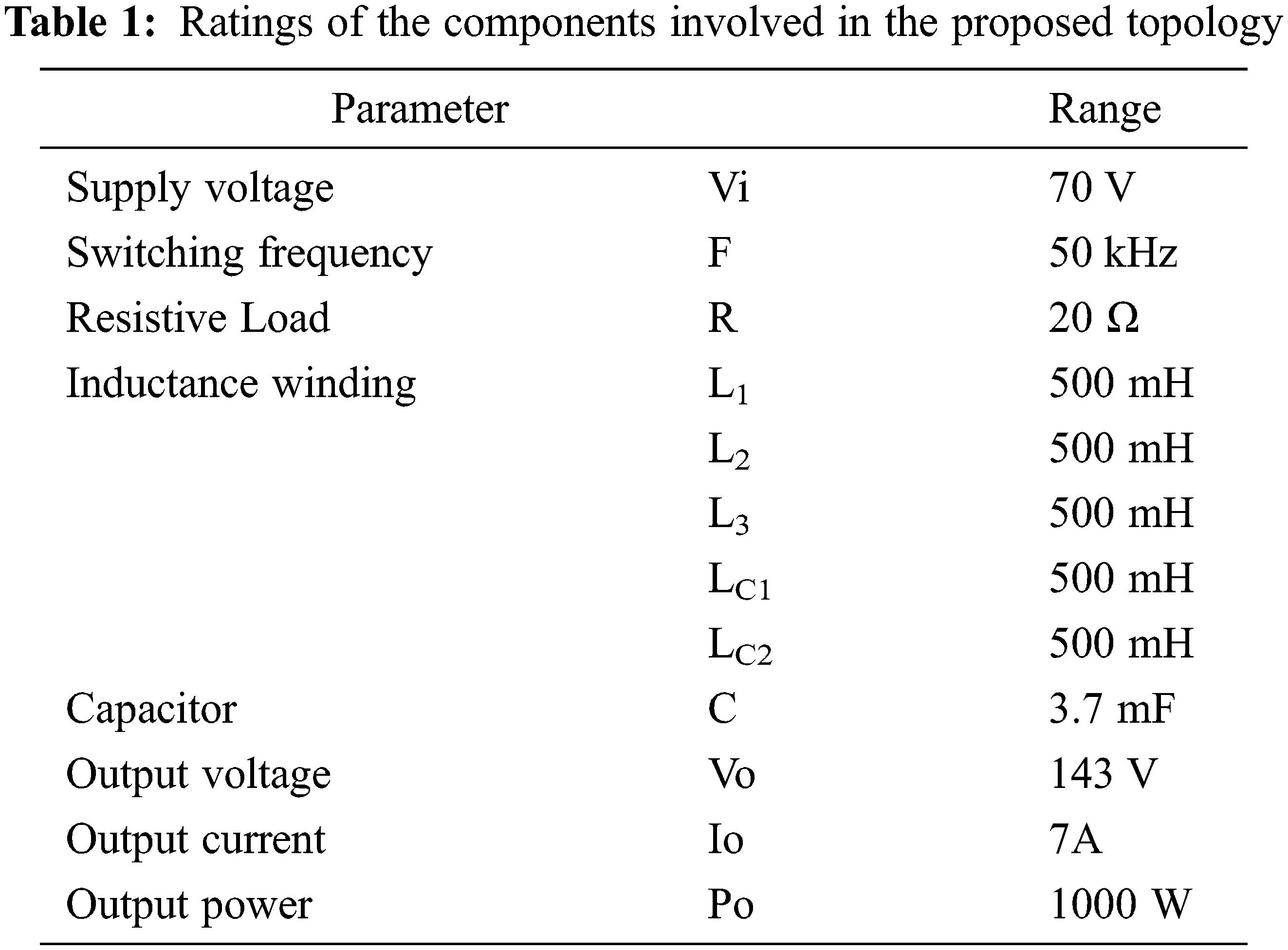
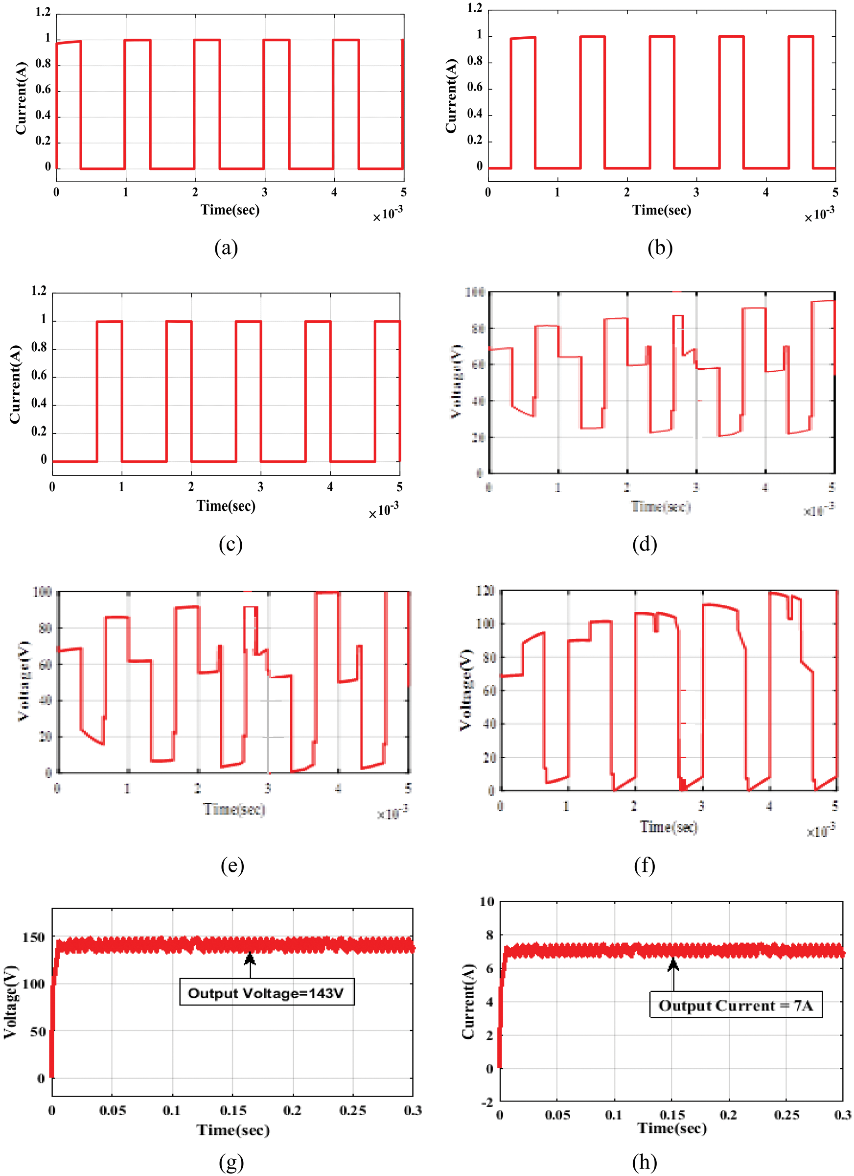
Figure 11: Proposed ISC converter’s MATLAB output waveforms without fuzzy switching current (a) IS1, (b) IS2, (c) IS3, Switching voltage, (d) VS1, (e) VS2, (f) VS3, (g) Output voltage, (h) Output current
5.1 MATLAB Simulation Result of ISC Converter
As shown in Tab. 1, the proposed Three-phase Interleaved Step-up DC-DC converter contains a number of parameters and an operating range that may be found in the table. A simulation of the proposed ISC converter circuit was carried out in MATLAB based on the operating range. Fig. 11 depicts the switching current, switching voltage, output current, and output voltage waveforms in the absence of a fuzzy controller, which is the open loop ISC Converter.
The output voltage and output current shown in Figs. 11g and 11h clearly show that when the undesirable ripple voltage and ripple current are present at the same time, the desired output voltage can be achieved. If there is ripple in a DC circuit, it wastes power and has a variety of undesirable effects, including heating components, creating noise, distortion, and causing digital circuits to operate incorrectly. By modifying the firing angle of the proposed converter, the fuzzy controller can minimise the undesired output ripples, hence improving the overall quality of the converter.
5.2 MATLAB Simulation Result with Fuzzy & Proportional Integral (PI) Controller
As illustrated in Fig. 12, the converter’s output voltage is sent to the PI Controller. In general, a PI controller performs well with lower-order systems because it eliminates steady-state error and high-frequency noise. The proposed ISC converter’s output voltage is routed through a PI controller, which also lowers voltage ripple. However, it decreases voltage gain, resulting in a decrease in output power. Hence, fuzzy control was used in the controller design process, and the results were promising in improving the adaptability of the proposed ISC Converter. The output waveforms of the proposed ISC Converter with fuzzy and PI controller are shown in Fig. 13. The proposed converter’s voltage regulation is improved by the use of a fuzzy controller rather than a PI controller.
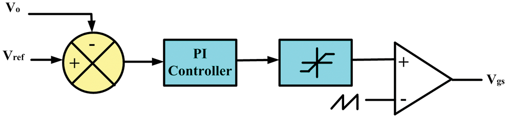
Figure 12: PI controller design
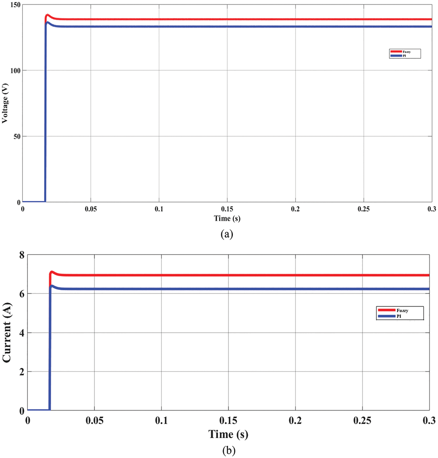
Figure 13: Simulated output waveform with fuzzy (a) Output Voltage (b) Output Current
There is more than 3% ripple in the voltage and current waveforms, as shown in Figs. 11g and 11h, raising the system temperature and revealing power quality issues such as waveform distortion and noise. Because of this, a fuzzy controller must be built to eliminate the disturbance and adjust the output voltage in direct proportion to the reference voltage, among other functions. As shown in Figs. 13a and 13b, the use of a fuzzy controller reduces ripple voltage and current to less than 2%, and the fuzzy controller provides a higher voltage gain than the PI.
The proposed converter is compared with the converter topology [1] with the same input voltage of both the converters. By comparing the experimental values, the proposed ISC Converter produced greater output performance than the converter topology published in [1]. The proposed ISC converter is a three-phase converter, and the converter topology published in [1] is a four-phase converter. The four-phase converter topology in [1] is very complex in constructional design with moderate output performance, and the proposed three-phase ISC converter is easy to design and will produce greater output performance, as shown in Fig. 14. Hence, this proposed converter topology is appropriate for EV applications.
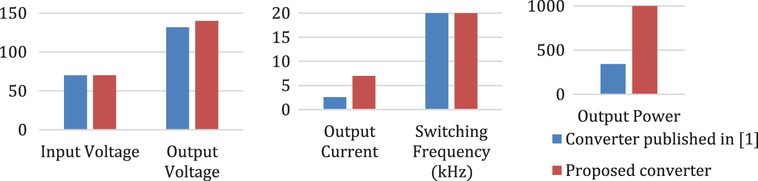
Figure 14: Statistical analysis comparison between ISC and converter topology [1]
From the simulated output waveforms, it is clearly understood that the proposed ISC Converter produces a high-power output (1 kW). Hence, this DC-DC converter design is appropriate for medium and high-power electric vehicle applications.
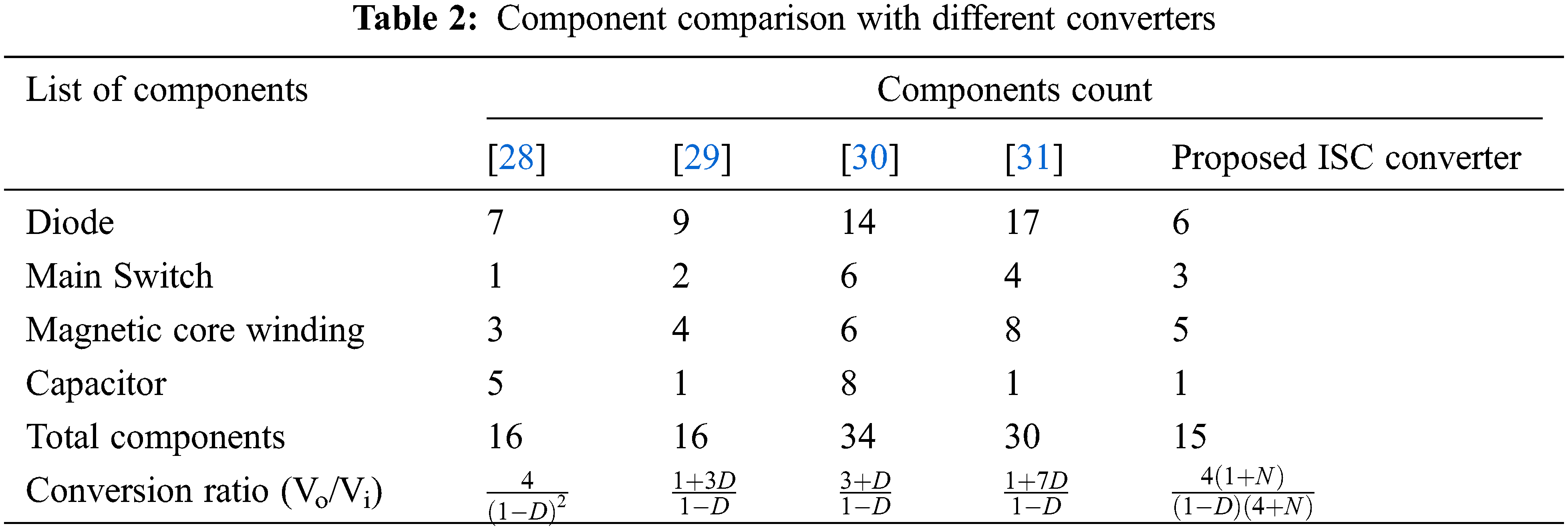
The comparison of output voltage, output current, and output power of a simulated waveform for the converter published in [1] and the proposed ISC Converter is shown in Fig. 15. The results obtained in the proposed three-phase ISC Converter topology are better than the four-phase converter topology published in [1]. The component comparison with different converters is shown in Tab. 2, which clearly shows the proposed converter has the reduced components. Hence, switching losses will be reduced.
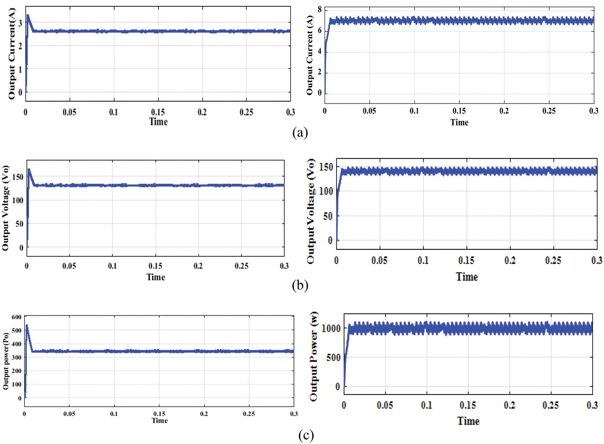
Figure 15: Simulated waveform for the converter published in [1] vs. the proposed ISC Converter (a) Output Current, (b) Output voltage, (c) Output Power
Thus, a fuzzy-based three-phase interleaved Step-up DC-DC converter has been developed and implemented. The modes of operation are discussed in detail, the component design is derived, and the flowchart for ripple reduction is constructed. The simulated output of the proposed ISC converter is displayed. The comparative output waveforms are displayed for both the fuzzy and the PI Controller. As a result, the proposed converter with a fuzzy controller provides better performance. The converter produces an output voltage of 143 V, an output current of 7A, and a power range of 1000 W or 1 kilowatt (kW). The proposed converter without fuzzy produces ripples in the output characteristics, whereas the proposed converter with fuzzy produces output characteristics with a minimum amount of ripple voltage. The reduced ripple voltage is 2.5 V, which is less than 2% of the output voltage. The output of the ISC Converter may be used by Fuzzy to make quick decisions on the response. It was verified that the proposed fuzzy-tuned ISC Converter had better output voltage responsiveness. Therefore, the proposed ISC converter’s performance is improved by the use of fuzzy soft computing techniques. During fluctuations in load, the fuzzy controller ensures that voltage and current travel through the converter without interruption.
Funding Statement: The authors received no specific funding for this study.
Conflicts of Interest: The authors declare that they have no conflicts of interest to report regarding the present study.
1. R. Saadi, M. Y. Hammoudi, O. Kraa, M. Y. Ayad and M. Bahri, “A robust control of a 4-leg floating interleaved boost converter for fuel cell electric vehicle application,” Mathematics and Computers in Simulation, vol. 167, pp. 32–47, 2020. [Google Scholar]
2. V. Karthikeyan, S. Kumaravel and G. Gurukumar, “High step-up gain DC-DC converter with switched capacitor and regenerative boost configuration for solar PV applications,” IEEE Transactions on Circuits and Systems II: Express Briefs, vol. 66, no. 12, pp. 2022–2026, 2019. [Google Scholar]
3. A. Kumar and P. Sensarma, “Ripple-free input current high voltage gain DC-DC converters with coupled inductors,” IEEE Transactions on Power Electronics, vol. 34, no. 4, pp. 3418–3428, 2019. [Google Scholar]
4. W. Hassan, D. D. C. Lu and W. Xiao, “Analysis and experimental verification of a single-switch high-voltage gain ZCS DC–DC converter,” IET Power Electronics, vol. 12, no. 8, pp. 2146–2153, 2019. [Google Scholar]
5. V. J. Samuel, G. Keerthi and P. Mahalingam, “Coupled inductor-based DC-DC converter with high voltage conversion ratio and smooth input current,” IET Power Electronics, vol. 13, no. 4, pp. 733–743, 2020. [Google Scholar]
6. S. Kumaravel, R. A. Narayanankutty, V. S. Rao and A. Sankar, “Dual input-dual output DC-DC converter for solar PV/battery/ultra-capacitor powered electric vehicle application,” IET Power Electronics, vol. 12, no. 13, pp. 3351–3358, 2019. [Google Scholar]
7. S. Saravanan, K. Karunanithi and S. Pragaspathy, “A novel topology for bidirectional converter with high buck boost gain,” Journal of Circuits, Systems and Computers, vol. 29, no. 14, pp. 2050222, 2020. [Google Scholar]
8. M. Premkumar, C. Kumar and R. Sowmya, “Analysis and implementation of high-performance DC-DC step-up converter for multilevel boost structure,” Frontiers in Energy Research, vol. 7, no. 149, pp. 1–11, 2019. [Google Scholar]
9. S. Zhuo, L. Xu, A. Gaillard, Y. Huangfu, D. Paireet et al., “Robust open-circuit fault diagnosis of multi-phase floating interleaved DC-DC boost converter based on sliding mode observer,” IEEE Transactions on Transportation Electrification, vol. 5, no. 3, pp. 638–649, 2019. [Google Scholar]
10. S. Zhuo, A. Gaillard, L. Guo, L. Xu, D. Paireet et al., “Active disturbance rejection voltage control of floating interleaved DC-DC boost converter with switch fault consideration,” IEEE Transactions on Power Electronics, vol. 34, no. 12, pp. 12396–12406, 2019. [Google Scholar]
11. Y. Sato, M. Uno and H. Nagata, “Non-isolated multiport converters based on integration of PWM converter and phase-shift-switched capacitor converter,” IEEE Transactions on Power Electronics, vol. 35, no. 1, pp. 455–470, 2020. [Google Scholar]
12. M. L. Alghaythi, R. M. O’connell and N. E. Islam, “Design of a high step-up DC-DC power converter with voltage multiplier cells and reduced losses on semiconductors for photovoltaic systems,” in Proc. IEEE ESTS, Washington, DC, USA, pp. 214–218, 2019. [Google Scholar]
13. Y. Zheng and K. M. Smedley, “Interleaved high step-up converter integrating coupled inductor and switched capacitor for distributed generation systems,” IEEE Transactions on Power Electronics, vol. 34, no. 8, pp. 7617–7628, 2019. [Google Scholar]
14. R. B. Sri, P. Mahalingam and F. Gonzalez-Longatt, “Interleaved high gain DC-DC converter for integrating solar PV source to DC bus,” Solar Energy, vol. 188, pp. 924–934, 2019. [Google Scholar]
15. G. Zhang, N. Jin, L. Qu and S. S. Yu, “Inherently non-pulsating input current DC-DC converter for battery storage systems,” IEEE Access, vol. 8, pp. 140293–140302, 2020. [Google Scholar]
16. S. Khan, A. Mahmood, M. Zaid, M. Tariq, C. H. Lin et al., “A high step-up DC-DC converter based on the voltage lift technique for renewable energy applications,” Sustainability, vol. 13, no. 19, pp. 11059, 2021. [Google Scholar]
17. S. Khan, M. Zaid, A. Mahmood, A. S. Nooruddin, J. Ahmad et al., “A new transformerless ultra high gain DC–DC converter for DC microgrid application,” IEEE Access, vol. 9, pp. 124560–124582, 2021. [Google Scholar]
18. M. H. Azam, M. H. Hasan, S. Hassan and S. J. Abdulkadir, “Fuzzy type−1 triangular membership function approximation using fuzzy C-means,” in Proc. ICCI, Bandar Seri Iskandar, Malaysia, pp. 115–120, 2020. [Google Scholar]
19. F. D. Murdianto, A. R. Nansur, N. A. Septiarini, K. Widarsono and E. Purwanto, “SEPIC converter with coupled inductor using fuzzy logic controller to optimized battery charging process,” Journal of Physics: Conference Series, vol. 1367, no. 1, pp. 012074, 2019. [Google Scholar]
20. T. Arunkumari and V. Indragandhi, “A fuzzy controlled high gain DC–DC converter for renewable power generation,” Journal of Intelligent & Fuzzy Systems, vol. 36, no. 5, pp. 4165–4176, 2019. [Google Scholar]
21. J. K. M. Kumar, H. A. Rauf and R. Umamaheswari, “An improved design for grid based PV control systems using modified fuzzy logic with an improved switched capacitor DC-DC converter,” Cluster Computing, vol. 22, no. 2, pp. 4221–4230, 2018. [Google Scholar]
22. H. Doubabi and I. Salhi, “Design and dspace implementation of a simplified fuzzy control of a DC-DC three-level converter,” Journal of Electrical and Computer Engineering, vol. 2021, pp. 5593572, 2021. [Google Scholar]
23. M. Bharathidasan, V. Indragandhi, R. Kuppusamy, Y. Teekaraman, U. Shabana et al., “Intelligent fuzzy based high gain non-isolated converter for DC micro-grids,” Computers, Materials and Continua, vol. 71, no. 2, pp. 4069–4084, 2022. [Google Scholar]
24. R. Thangam and S. P. J. V. Rani, “Nonlinear controller: Voltage controlled PFC–based fuzzy MDPSM controller with predictive input voltage,” Journal of Circuits, Systems and Computers, vol. 29, no. 13, pp. 2050207, 2020. [Google Scholar]
25. A. Rajavel and N. R. Prabha, “Fuzzy logic controller-based boost and buck-boost converter for maximum power point tracking in Solar System,” Transactions of the Institute of Measurement and Control, vol. 43, no. 4, pp. 945–957, 2021. [Google Scholar]
26. C. S. Shieh, “Constant voltage/current with slowly rising control for high power DC-DC converter based on FPGA digital control,” Journal of Intelligent & Fuzzy Systems, vol. 36, no. 2, pp. 885–895, 2019. [Google Scholar]
27. E. Y. Bejarbaneh, A. Bagheri, B. Y. Bejarbaneh, S. Buyamin and S. N. Chegini, “A new adjusting technique for PID type fuzzy logic controller using PSOSCALF optimization algorithm,” Applied Soft Computing, vol. 85, pp. 105822, 2019. [Google Scholar]
28. M. Zaid, C. H. Lin, S. Khan, J. Ahmad, M. Tariq et al., “A family of transformerless quadratic boost high gain DC-DC converters,” Energies, vol. 14, no. 14, pp. 4372, 2021. [Google Scholar]
29. N. Gupta, M. S. Bhaskar, D. Almakhles, P. Sanjeevikumar, U. Subramaniam et al., “Novel non-isolated quad-switched inductor doubleswitch converter for DC microgrid application,” in Proc. EEEIC/I&CPS, Madrid, Spain, pp. 1–6, 2020. [Google Scholar]
30. M. Maalandish, S. H. Hosseini, S. Ghasemzadeh, E. Babaei, R. S. Alishah et al., “Six-phase interleaved boost dc/dc converter with high-voltage gain and reduced voltage stress,” IET Power Electronics, vol. 10, no. 14, pp. 1904–1914, 2017. [Google Scholar]
31. E. Babaei, H. M. Maheri, M. Sabahi and S. H. Hosseini, “Extendable non isolated high gain DC-DC converter based on active–passive inductor cells,” IEEE Transactions on Industrial Electronics, vol. 65, no. 12, pp. 9478–9487, 2018. [Google Scholar]
 | This work is licensed under a Creative Commons Attribution 4.0 International License, which permits unrestricted use, distribution, and reproduction in any medium, provided the original work is properly cited. |