DOI:10.32604/iasc.2023.025510
| Intelligent Automation & Soft Computing DOI:10.32604/iasc.2023.025510 | |
| Article |
Optimized Power Factor Correction for High Speed Switched Reluctance Motor
Sri Sivasubramaniya Nadar College of Engineering, Kalavakkam, Tamilnadu, 603110, India
*Corresponding Author: R. S. Preethishri. Email: preethishrisld@gmail.com
Received: 26 November 2021; Accepted: 12 February 2022
Abstract: The Power Factor Correction (PFC) in Switched Reluctance (SR) motor is discussed in this article. The SR motors are applicable for multiple applications like electric vehicles, wind mills, machineries etc. The doubly salient structure of SR motor causes the occurrence of torque ripples, which affects the power factor of the motor. To improve the power quality, the power factor has to be corrected and the ripples have to be minimized. In order to achieve these objectives, a novel power factor correction (PFC) method is proposed in this work. Here, the conventional Diode Bridge Rectifier (DBR) is replaced by a Bridgeless Hybrid Resonant (HR) converter, which assists in improvising the output in a wider range. The converter is chosen because of having variety of beneficial measures including high gain. The converter’s output is fed to the SR motor by means of an asymmetric Bridge Resonant (BR) converter. The proposed converter operates in continuous mode of conduction with the switching frequency of 10 KHz. A hysteresis current controller and Proportional Integral (PI) controller are utilized for reducing the harmonics in the source current along with the regulation of output voltage. In addition, the speed control of SR motor is accomplished by means of the Whale Optimization Algorithm (WOA) assisted PI controller. The proposed methodology is effective for the control of unity power factor, torque and current ripples. The Total Harmonic Distortion (THD) of the source current is also minimized, which suits the standard of International Electrotechnical Comission IEC 61000-3-2. By this methodology, the power factor of 0.99 is achieved with 97% efficiency and 3.92% THD. The proposed methodology is validated in simulation by MATLAB and in hardware by FPGA Spartan 6E.
Keywords: Bridgeless hybrid resonant converter; switched reluctance motor; BR converter; hysteresis current controller; PI controller; WOA
The Switched Reluctance (SR) motors are applicable for the typical high-speed operations because of its beneficial factors like robust construction, low cost, less weight, lower winding losses and variable speed operations [1]. Though SR motors has several advantages, the torque ripple and noise makes it disadvantageous. As SR motor is the doubly salient structured machine, the occurrence of torque ripples is unavoidable in nature. However, these ripples are rectified either by improvising the machine design or by the electronic control methods [2]. Numerous torque ripple minimization techniques are discussed in literature. Fuzzy logic algorithm, reducing the ripples, pools the unknown load torque with the produced torque is proposed in [3]. A combined design of the machine and controller is presented for torque ripple reduction in [4] by considering the coupling effect. The positive or negative compensations are utilized and a hybrid chopping mode is established to drop the switching losses as discussed in [5]. Based on the current profiling method, under normal and faulty condition the torque ripples are minimized [6]. Generally, the large number of phases in SR motors results in lower torque ripple. In [7], a new control scheme had been presented to reduce these ripples. For minimizing the computational difficulty, a finite-state predictive control has been utilized, which aids in reducing the torque ripples and copper losses on the basis of sector-partition technique [8]. The optimal current profiles has been determined based on the flux linkage features that are attained from the finite element analysis to minimize the torque ripples [9]. The Direct Instantaneous Torque Control (DITC) and Current Control (CC) have been implemented instantaneously to control the phases, which delivers low ripple for moderate and high-speed operations [10]. The sense coil mechanism implemented by calculating the instantaneous inductance, generates a current profile to diminish the ripple and copper losses [11]. The PFC is necessary in SR motors and so several topologies employed for obtaining the PFC.
A simplified control has been implemented, which aids the converter to run in both Pulse Width Modulation (PWM) and resonant mode for attaining minimum switching losses [12]. A topology, which excludes electrolytic capacitors and facilitates twice-line frequency has been defended at high voltage resulting in miniaturization and high-power factor [13]. In [14], power factor correction (PFC) has been carried out by two controllers that are independently controlled by sliding mode control. SR motor drive with incorporated PFC during the starting time is implemented with an effective control algorithm for split-AC is discussed in [15]. The enactment of switched reluctance motor with CUK converter is observed for enhancing power quality requirements is discussed in [16]. Better voltage regulation and PFC is achieved by means of Modified Quasi Z-source Converter (MQZSC) fed SRM drive resulting in the reduction of total harmonic distortion is discussed in [17]. PFC in SR motors is accomplished by different converters such as CUK; CUK and Single-Ended Primary-Inductor Converter (SEPIC) [18]; modified SEPIC [19]; modified dual output CUK [20]; half-bridge dual output converter [21]. In all these existing converters that are applicable for PFC, there exist the problem of return current and hence an effective topology for PFC in SR motor is proposed in this work. Speed control is a vital part and generally PI controllers and Fuzzy controllers are employed for controlling the speed of the SR motor. The PI controller results in peak overshoot while the fuzzy controllers requires more data for processing and so in this work, optimization techniques has been employed for tuning the PI controller parameters [22–24].
Bridgeless HR converter is introduced in this paper in which diodes are utilized, by which the problem of return current is eliminated; also, no additional filters are required, as the topology itself acts as a low-pass filter because of the presence of inductor and capacitor. The proposed system operates under continuous mode of conduction at a switching frequency about 10 KHz. PI controller incorporated with hysteresis current controller is implemented in both converter side and the motor side which results in the power factor improvement along with torque and current ripple minimization. In this work, power factor correction in SR Motor is carried out by means of Bridgeless Hybrid Resonant (HR) converter. The proposed strategy and the modeling of proposed converter, Hysteresis current control, SR motor, BR converter and the simulation results are revealed in the upcoming sections.
As the rotor and stator of switched reluctance (SR) motor are made of silicon steel laminations, more ripples are produced in the current and torque which results oscillations in the speed. Also because of the usage of diode bridge rectifier (DBR) and back Electro Motive Force (EMF) in SR motors, harmonics are induced in the source which makes the input current non-sinusoidal. Due to the presence of coils in the stator, displacement of voltage and current takes place which affects the power factor. The diagrammatic representation of the proposed methodology is in Fig. 1. In the conventional methods, DBR is incorporated with boost or buck-boost or CUK or Single-Ended Primary-Inductor Converter (SEPIC) or push-pull converters but still there exist fluctuations in the power factor. In push-pull converter, AC-DC conversion takes place in two stages which makes the process complicated. In this paper, the diode is replaced with insulated gate bipolar transistor (IGBT) while the converter is replaced by bridgeless hybrid resonant (HR) converter. In this converter there exist diodes by which the problem of return current is rectified, but harmonics are still existing in the injected current and to eliminate this, a PI controller is instigated.
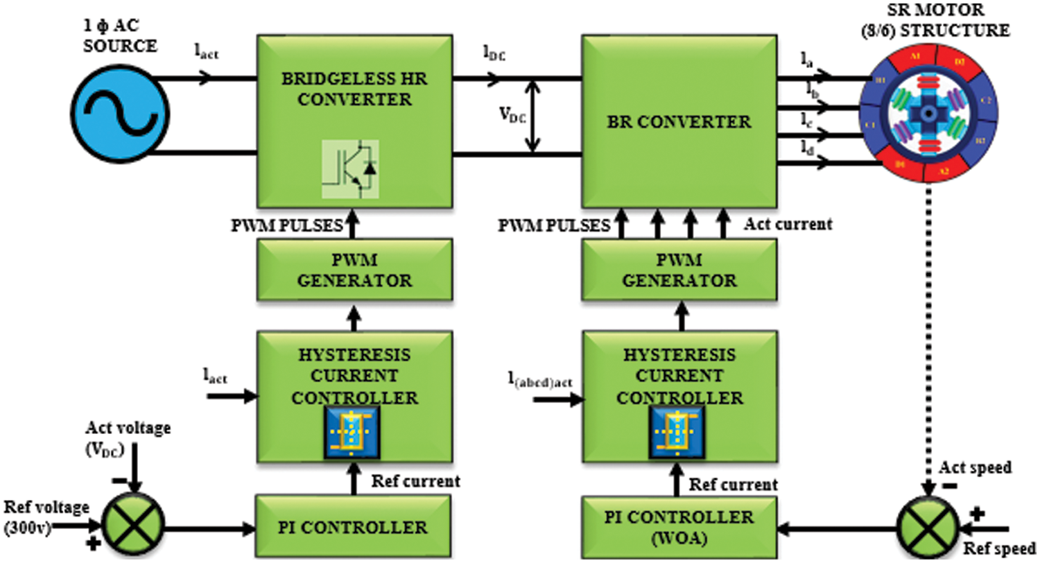
Figure 1: Work flow of the proposed method
Actual voltage obtained from the output of bridgeless HR converter and the reference voltage of 300 V are compared and fed to the PI controller as input. Now a hysteresis current controller is introduced which compares the reference current with the actual current, and the generated pulses are nourished to the bridgeless HR converter by which the voltage is retained and so the current will be pure sinusoidal and thus the power factor correction is achieved. In the motor side, as load is applied the speed of the motor decreases and so there exist torque and current ripples. The reference and the actual speed are analogized, and the error is given to the PI controller in which the parameters are tuned with whale optimization and the output is attained in terms of current. When load is applied there is a variation in the actual current. And so, a hysteresis current controller is instigated which compares the actual and reference current and the pulses are generated which is fed to the switching converter of SR motor. As diodes are present in the converter setup, it is not possible for the return current to reach the source. Hence the proposed methodology is effective for the torque and current ripple minimization with unity power factor.
3 Modelling and Proposed Method
In this paper the power factor correction in SR motors is achieved by Bridgeless Hybrid Resonant (HR) converter. The use of diode bridge rectifier is excluded in HR bridgeless converter. The diagrammatic illustration of bridgeless HR converter is as shown in Fig. 2.
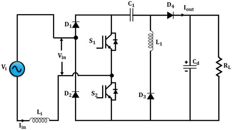
Figure 2: Illustration of bridgeless HR converter
Here, the PWM signal given for both the switches are same. During the starting phase, the converter drives at a duty cycle of low range. When S1 and S2 are ON, the converter drives in HR mode and when they are OFF, it drives in PWM mode. It is also noted that the resonant frequency is more or less or same as that of the switching frequency. Li, L1 and C1 refer to the input inductor, resonant inductor and resonant capacitor respectively. The waveforms of bridgeless HR converter are shown in Fig. 3. Considering the working of the converter for positive ac half-line cycle, the modes of operation of bridgeless HR converter is illustrated as follows:
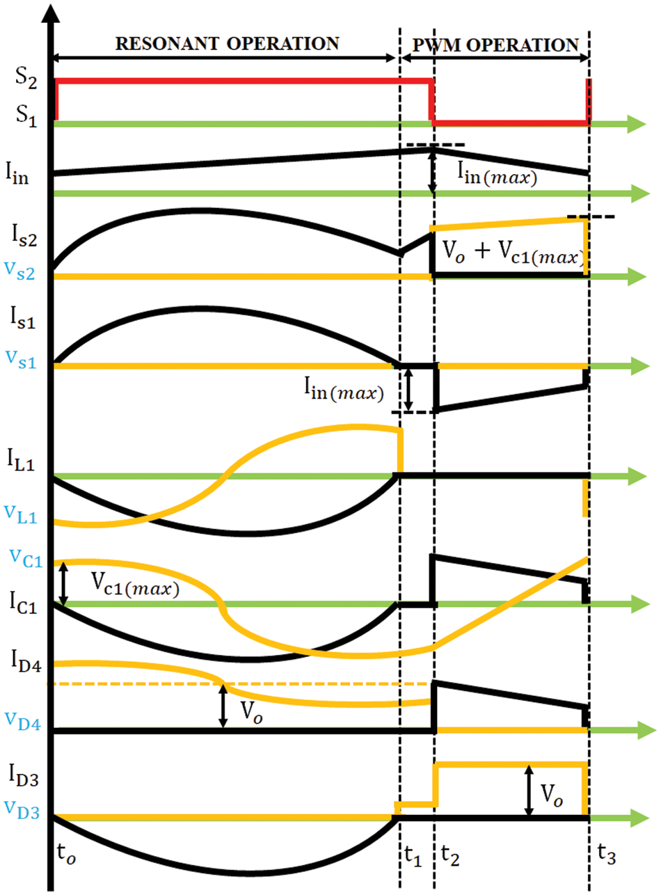
Figure 3: Waveforms of bridgeless HR converter
Mode 1
In this mode
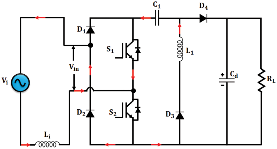
Figure 4: Bridgeless HR converter-Mode 1
Mode 2
When D3 stops conducting, the mode 2 operation starts and at this instant no current passes through the resonant inductor and capacitor. In this mode also Li stores energy continuously which is represented in Fig. 5. This mode ends when the switches are OFF.
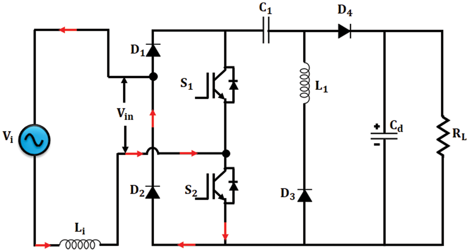
Figure 5: Bridgeless HR converter-Mode 2
Mode 3
The energy in the inductor Li is fed to the load which is illustrated in Fig. 6. This mode ends when the switches are ON and then again mode 1 operation starts.

Figure 6: Bridgeless HR converter-mode 3
Under normal operating condition the Voltage-conversion ratio of bridgeless HR converter is in (5) which resembles boost converter.
The power factor correction in SR motor is done by means of bridgeless converter. In order to attain constant voltage from the converter, the hysteresis current controller incorporated with PI controller is implemented. By which the output voltage is made constant and the input current is continuous.
An 8/6 SR motor scrutinized in this paper which is a four-phase motor with 8 stator poles-6 rotor poles. All phases are considered to be identical, ignoring the mutual inductance amid the phases. Equation for applied voltage to the phase with respect to time is as follows:
where L is the inductance, Rs and ψ are the resistance and the flux linkage per phase respectively. The phase voltage in terms of inductance is given as follows:
In Eq. (10), the terms in the Right Hand Side (RHS) signify voltage drop, inductive voltage drop, induced Electro Motive Force (EMF) correspondingly. EMF induced is given as,
EMF constant
SR motor equivalent circuit to single phase given at Fig. 7.

Figure 7: Equivalent circuit of SR motor-single phase
Instantaneous input current is given as follows:
But,
Thus, Pi is given as the addition of resistive loss, rate of change of field energy yet air gap power which is denoted by Pa.
Expression for time
Air gap power in terms of time is expressed as,
Thus, Pa can be shown as the product of torque and rotor speed,
The direction of current as
The output of the converter is fed to the Switched Reluctance (SR) motor by means of Bridge Rectifier (BR) converter. One of the advantages of using this converter is that each phase will conduct individually i.e., the motor can run in a single phase when the other three phases fail to operate. The schematic representation of BR converter is shown in Fig. 8. This converter comprises two semiconductor switching devices and two diodes in each phase. Here the windings are energized according to the rotor’s position.
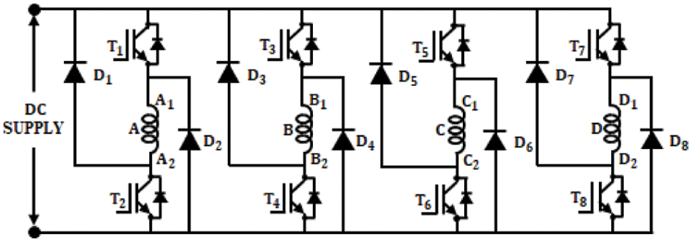
Figure 8: Circuit diagram of BR converter
When winding A is energized, T1 and T2 are ON and when the winding is detached from the supply T1 and T2 are OFF. In the OFF condition, the energy stored in the winding passes through the diodes D1 and D2 and thus the return current reaches the supply. The operation is similar for the other phases also. When this topology is applied for high-speed operations, it is noted that the stored energy should be nourished to the supply within the available time. Usually, switching ON and OFF of the upper leg switches T1, T3, T5, T7 are based on the position of the rotor while the controlling of the lower leg switches T2, T4, T6, T8 are based on the chopping frequency signal. Appropriate control circuits are used for controlling the angle of conduction θ.
3.4 Whale Optimization Algorithm for SR Motor Speed Control
The SR motor’s speed is controlled through the BR converter. At the initial stage motor starts running, but when load is applied, the speed of the motor decreases. Also, ripples are produced in the current as well as in the torque. To overcome this, PI controller is implemented which is tuned using whale optimization algorithm and tuning of these controllers relies on the dynamic system response. The PI controller controls the error and assigns appropriate signal to the system, which is represented in Eq. (21) and the time domain representation is in Eq. (22),
where Kp is the proportional gain and
Here, the current iteration is represented as
The coefficient vectors
The random vector is denoted by
The constant for defining the shape of the logarithmic spiral is denoted by b, the random number
3.5 Hysteresis Current Controller for SR Motor
The reference current thus obtained from PI controller is fed to the hysteresis current controller and the schematic representation of Hysteresis current controller (HCC) is in Fig. 9. When the motor runs at low speed, the back-emf is minimum and so current chopping is utilized to control the current flow through the stator winding hence, this control is chosen here. The actual and the reference speeds are analogized at the PI controller and the resultant reference signal is fed to the HCC. From the position sensor, the commutation controller takes the position and chooses the phase to be turned ON. Thus the

Figure 9: Hysteresis current controller
The main objective of employing Hysteresis current controller is, throughout the conduction period the current is maintained within the hysteresis band (
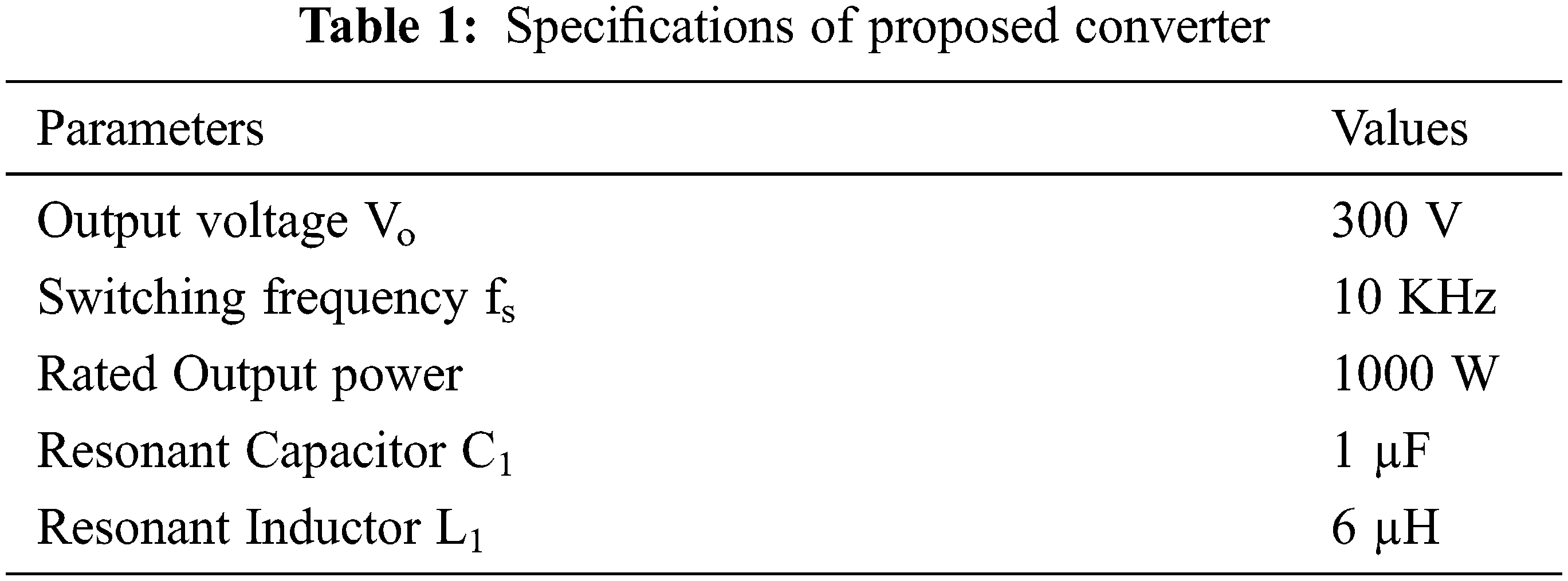
Power factor correction in SR motors with bridgeless HR converter is proposed in this paper. The performance of the proposed methodology is analyzed in MATLAB simulation and in hardware using FPGA Spartan 6E. The specifications used for simulation is shown in Tab. 1.
A four phase SR motor is analyzed in this work. When an input of 230 V AC is applied, initially there exist harmonics, the voltage and current illustrations are highlighted in Fig. 10.
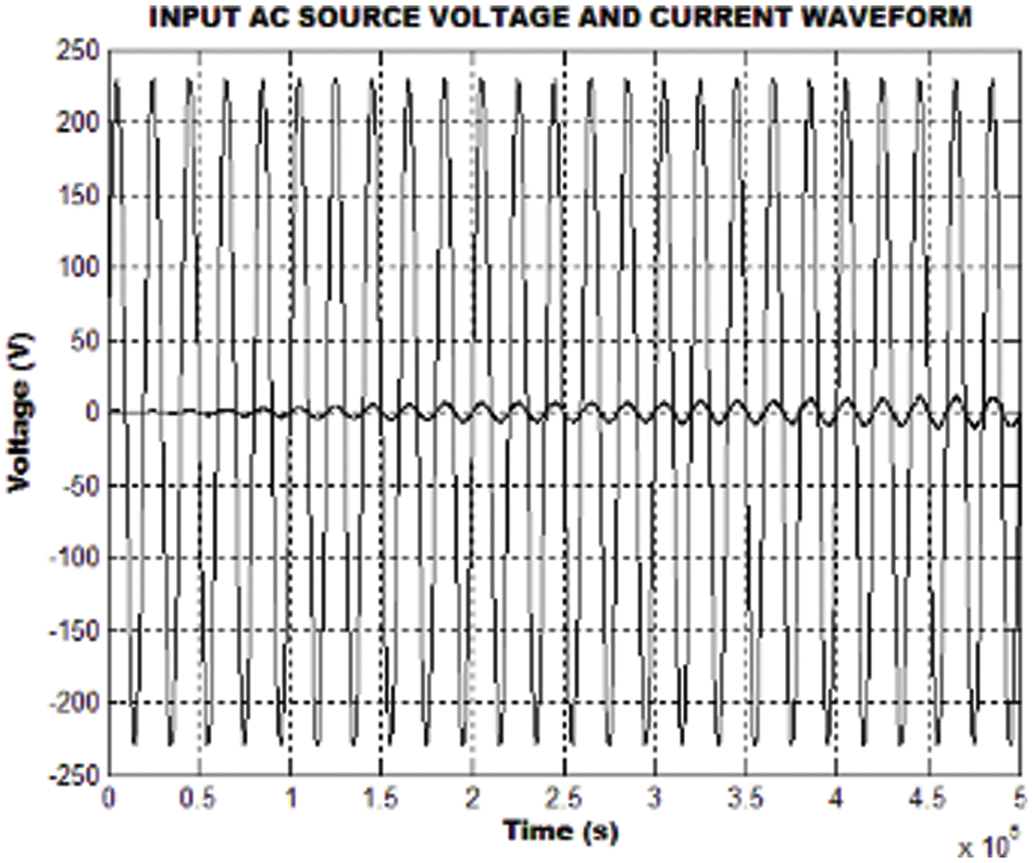
Figure 10: Input AC voltage and current
The output of the bridgeless HR converter is shown in Fig. 11. From the waveform it is noticed that the output voltage settles around 0.25 s. Even though different loads are applied, the output voltage remains unaffected.
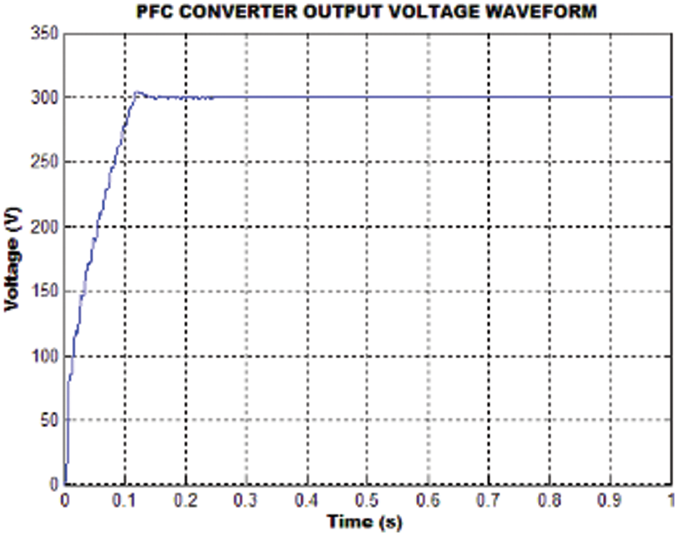
Figure 11: Converter output voltage
Generally, the starting current of the motor is more and after a certain time this tends to be normal. The analysis is done for various loading conditions. Here the waveforms for phase A are only shown, as all the other phases resembles phase A. Fig. 12 shows the current waveforms for different loading conditions like no load, 1, 2, 3 and 4 N-m.
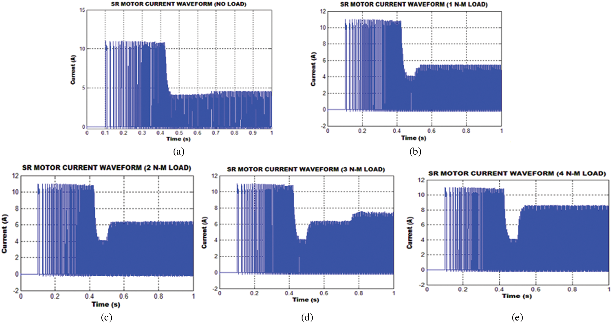
Figure 12: Current waveform at different loading conditions
Load is applied after 0.5 s and it is observed from Fig. 12, that there exist some variations and then the motor runs in a constant speed. It is also observed that even though variable loads are applied the voltage and current remains unaffected. The flux waveforms of Switched Reluctance motor for different loading conditions are as depicted in Fig. 13. The loading conditions includes no load, 1, 2, 3 and 4 N-m.

Figure 13: Flux waveforms for different loading conditions
The torque waveforms obtained as a result of simulation is as in Fig. 14. These waveforms are also analyzed for different loading conditions. In the starting time the torque is more and after that it tends to be normal.

Figure 14: Torque waveforms at different loading conditions
Speed control of SR motor is achieved by means of PI controller tuned with whale optimization algorithm and the speed waveforms observed for various loads is depicted in Fig. 15. From the waveforms it is depicted that for any variation in load the settling time remains the same as around 0.6 s. It is also observed that there is no problem with the maximum peak overshoot.

Figure 15: Speed waveforms at different loading conditions
The power factor correction (PFC) in Switched Reluctance Motor (SRM) is carried out by using of bridgeless Hybrid Resonant (HR) converter. This is achieved by using hysteresis current controller incorporated with Proportional Integral (PI) controller tuned by whale optimization algorithm. From the above simulation results it has been observed that the performance of the motor is unaffected under different loading conditions which is validated in hardware by using FPGA Spartan 6E controller (Fig. 16a).
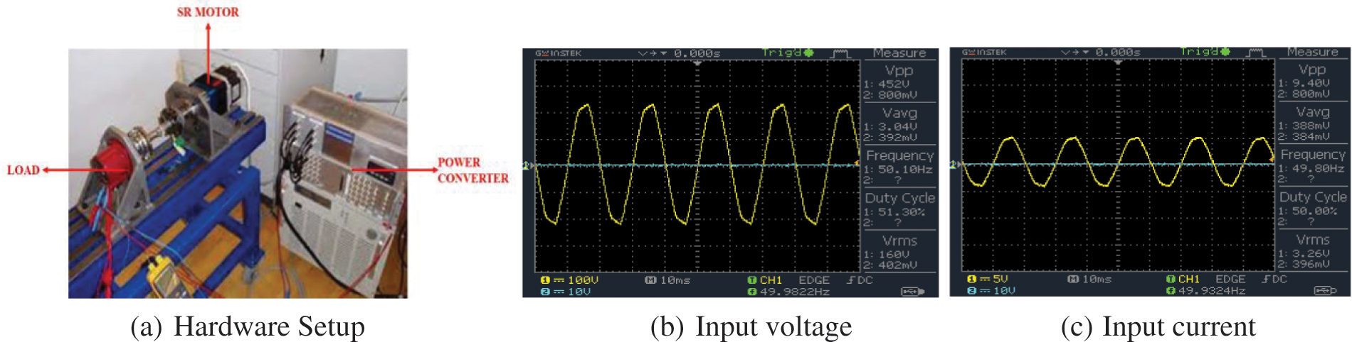
Figure 16: (a) Hardware Setup (b) Input voltage (c) Input current
The input voltage and current illustrations are displayed in Figs. 16b and 16c and the Bridgeless HR converter’s output voltage waveform is as highlighted in Fig. 17; it has been revealed that there are no variation even different loads are applied.
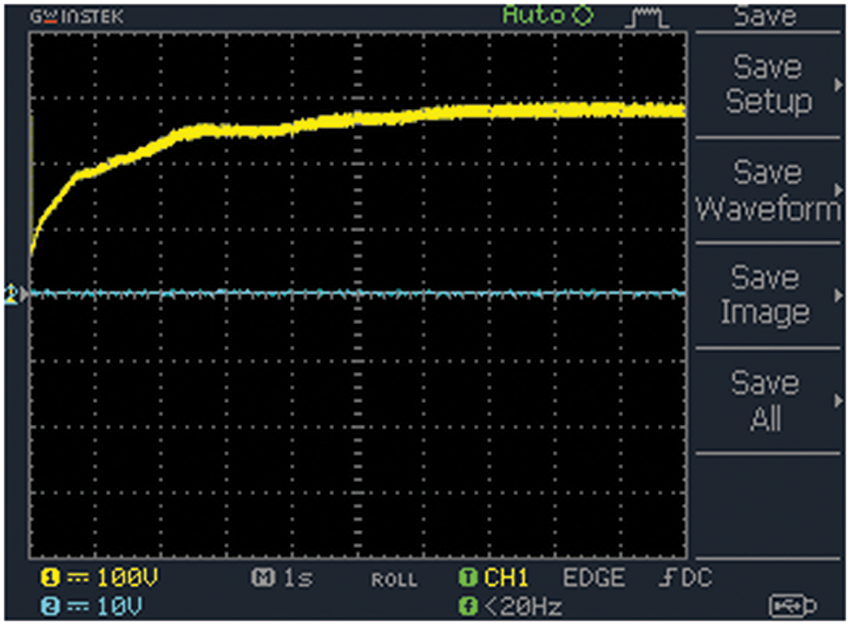
Figure 17: Output voltage of converter
From the hardware implementation of the proposed methodology, the waveforms for Current Fig. 18a, Flux Fig. 18b, Torque Fig. 18c, Speed Fig. 18d are observed and it has been noted that the motor speed is not affected though there occurs oscillations in the current, torque and flux.
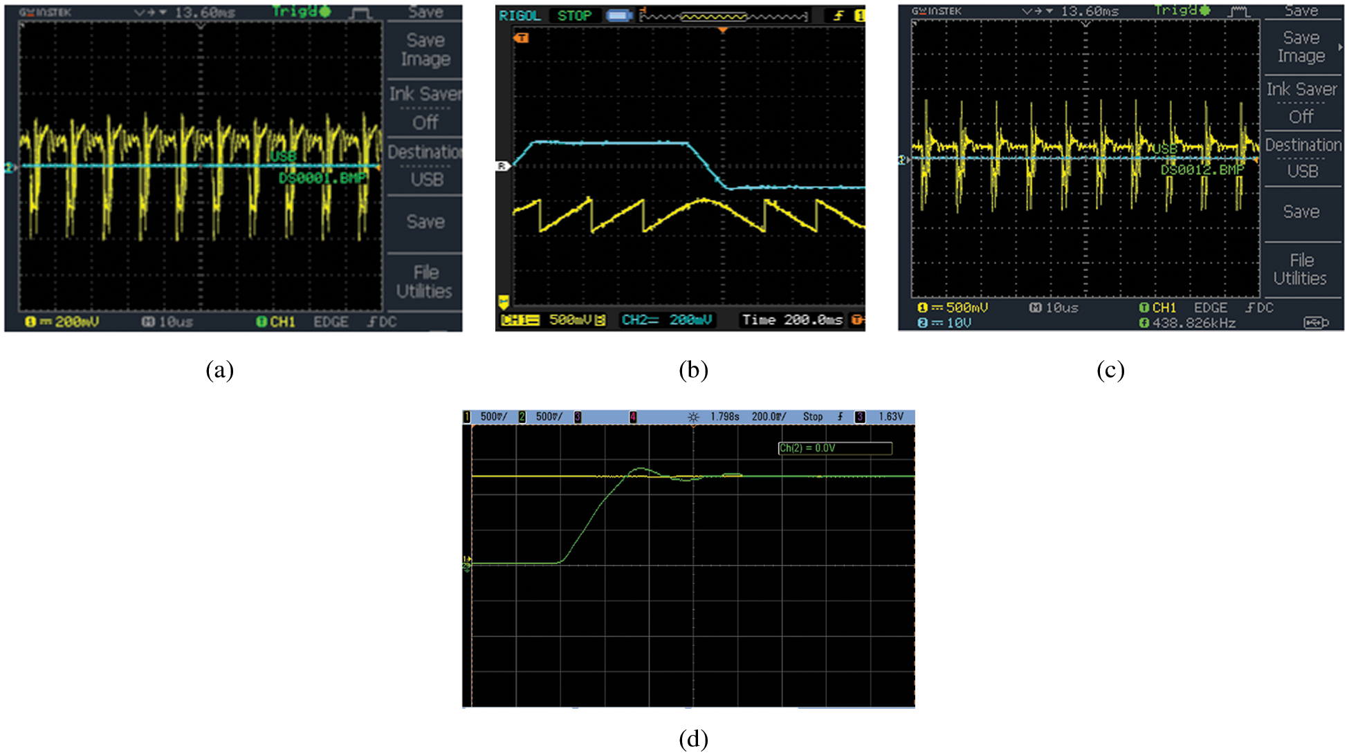
Figure 18: (a) Current waveform, (b) Flux waveform, (c) Torque waveform, (d) Speed waveform
The power factor and total harmonic distortion (THD) illustration are given in Figs. 19a and 19b respectively; it has been noted that the THD of 3.92% is observed which shows the effectiveness of the methodology.
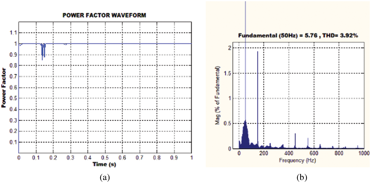
Figure 19: (a) Power factor representation (b) THD
The enactment of the proposed Hybrid Resonant (HR) converter is analogized with that of SEPIC, push-pull and boost converters in case of efficiency, power factor, voltage gain and THD as depicted in Fig. 20. From Fig. 20a, it has been observed that the efficiency of the proposed converter is 97% while the other converters show relatively lesser efficiency. The comparison of power factor for different converters is given in Fig. 20b and it has been observed that the power factor of 0.999 is accomplished.
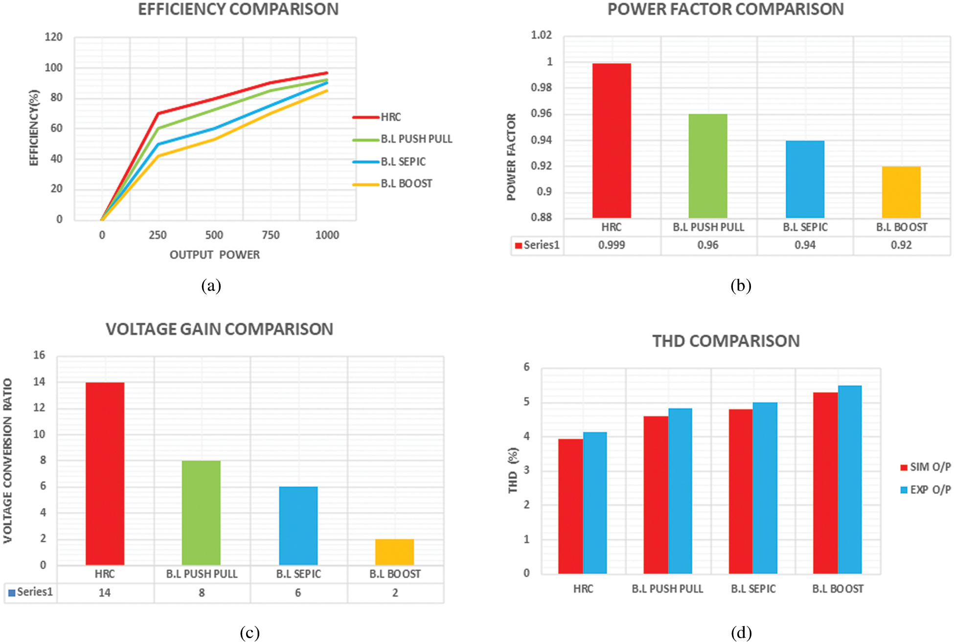
Figure 20: (a) Comparison of efficiency (b) Comparison of power factor (c) Comparison of voltage gain (d) Comparison of THD
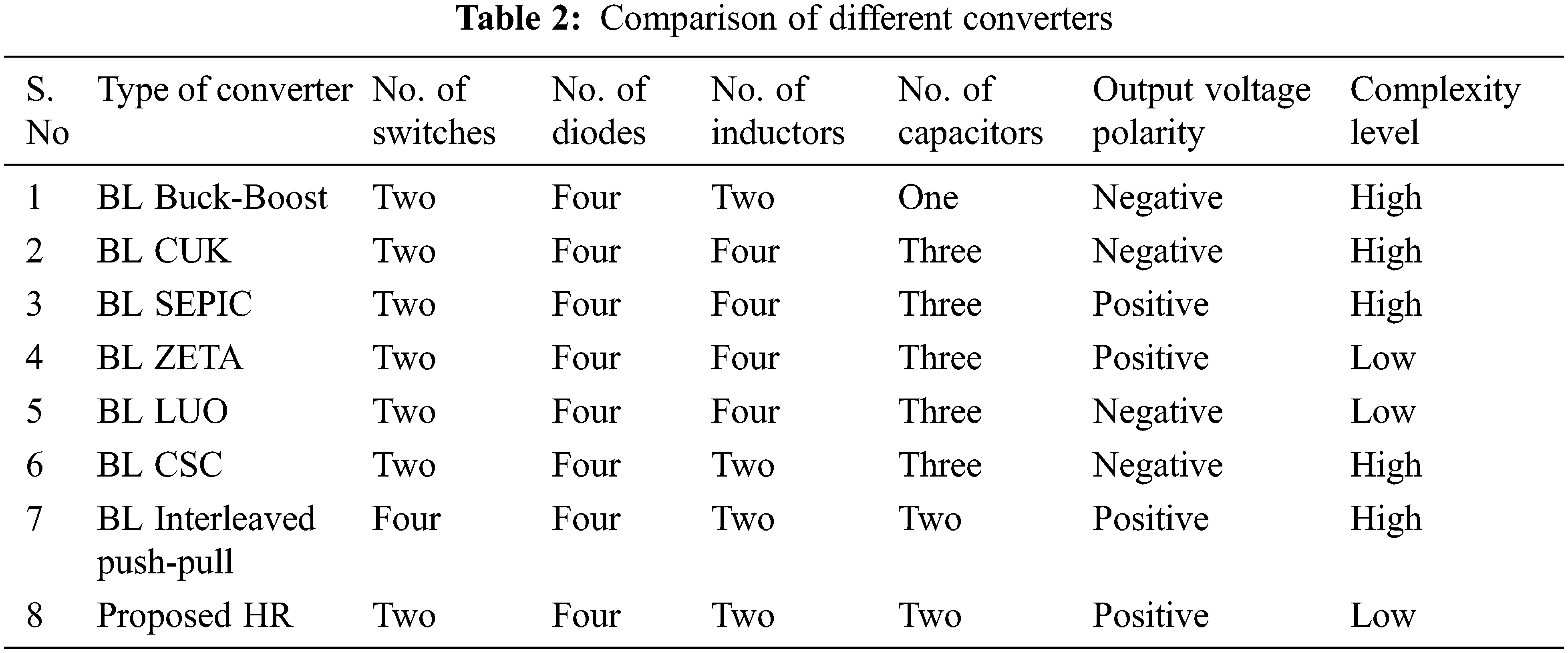
While comparing the voltage gain of various converters, it has been revealed that the voltage gain of HR converter is obtained as 14, which is relatively more when analogized with other converters as displayed in Fig. 20c. Fig. 20d represents the THD observed for different converters while the THD of the proposed converter is observed as 3.92%. Tab. 2 shows the comparison of different converters based on the devices used and its complexity.
The power factor correction of switched reluctance motor with a bridgeless hybrid resonant (HR) converter is analyzed in this paper, in which the problem of reverse current is eliminated by the use diodes in the converter; also, the converter operates under continuous mode of operation with a high voltage gain. The hysteresis current controller is utilized which assists in making the input current sinusoidal while the voltage and current are in-phase resulting in the improvement of power factor. The speed of the SR motor is retained with the assistance of proportional integral (PI) controller tuned with Whale Optimization Algorithm through simulation in MATLAB. The system has been verified for different loads and it has been observed that the speed of the motor remains without any change. As power factor correction (PFC) is the foremost intent of this paper, the power factor has been observed as 0.99 while the efficiency of HR converter is observed as 97% with a total harmonic distortion (THD) of 3.92% which satisfies the IEC 61000-3-2 standards. Also, the comparison of the existing converters with the proposed converter is shown which proves the superiority of the proposed methodology.
Funding Statement: The authors received no specific funding for this study.
Conflicts of Interest: The authors declare that they have no conflicts of interest to report regarding the present study.
1. K. Ha, C. Lee, J. Kim, R. Krishnan and S. Oh, “Design and development of low-cost and high-efficiency variable-speed drive system with switched reluctance motor,” IEEE Transactions on Industry Applications, vol. 43, no. 3, pp. 703–713, 2007. [Google Scholar]
2. I. Husain, “Minimization of torque ripple in SRM drives,” IEEE Transactions on Industrial Electronics, vol. 49, no. 1, pp. 28–39, 2002. [Google Scholar]
3. I. Agirman, A. M. Stankovic, G. Tadmor and H. Lev-Ari, “Adaptive torque-ripple minimization in switched reluctance motors,” IEEE Transactions on Industrial Electronics, vol. 48, no. 3, pp. 664–672, 2001. [Google Scholar]
4. R. Mikail, I. Husain, M. S. Islam, Y. Sozer and T. Sebastian, “Four-Quadrant torque ripple minimization of switched reluctance machine through current profiling with mitigation of rotor eccentricity problem and sensor errors,” IEEE Transactions on Industry Applications, vol. 51, no. 3, pp. 2097–2104, 2015. [Google Scholar]
5. Q. Sun, J. Wu, C. Gan, Yihua and J. Si, “OCTSF for torque ripple minimisation in SRMs,” IET Power Electronics, vol. 9, no. 14, pp. 2741–2750, 2016. [Google Scholar]
6. P. Dúbravka, P. Rafajdus, P. Makyš and L. Szabó, “Control of switched reluctance motor by current profiling under normal and open phase operating condition,” IET Electric Power Applications, vol. 11, no. 4, pp. 548–556, 2017. [Google Scholar]
7. X. Deng, B. Mecrow, H. Wu and R. Martin, “Design and development of low torque ripple variable-speed drive system with six-phase switched reluctance motors,” IEEE Transactions on Energy Conversion, vol. 33, no. 1, pp. 420–429, 2018. [Google Scholar]
8. C. Li, G. Wang, Y. Li and A. Xu, “An improved finite-state predictive torque control for switched reluctance motor drive,” IET Electric Power Applications, vol. 12, no. 1, pp. 14–151, 2018. [Google Scholar]
9. H. Li, B. Bilgin and A. Emadi, “An improved torque sharing function for torque ripple reduction in switched reluctance machines,” IEEE Transactions on Power Electronics, vol. 34, no. 2, pp. 1635–1644, 2019. [Google Scholar]
10. T. Husain, A. Elrayyah, Y. Sozer and I. Husain, “Unified control for switched reluctance motors for wide speed operation,” IEEE Transactions on Industrial Electronics, vol. 66, no. 5, pp. 3401–3411, 2019. [Google Scholar]
11. B. P. Reddy, J. R. Vemula and S. Keerthipati, “Torque ripple minimisation of switched reluctance motor using sense coils,” IET Electric Power Applications, vol. 14, no. 4, pp. 614–621, 2020. [Google Scholar]
12. M. Alam, W. Eberle, D. S. Gautam and C. Botting, “A soft-switching bridgeless AC-DC power factor correction converter,” IEEE Transactions on Power Electronics, vol. 32, no. 10, pp. 7716–7726, 2017. [Google Scholar]
13. S. Lim, D. M. Otten and D. J. Perreault, “New AC-DC power factor correction architecture suitable for high-frequency operation,” IEEE Transactions on Power Electronics, vol. 31, no. 4, pp. 2937–2949, 2016. [Google Scholar]
14. A. Marcos-Pastor, E. Vidal-Idiarte, A. Cid-Pastor and L. Martinez-Salamero, “Interleaved digital power factor correction based on the sliding-mode approach,” IEEE Transactions on Power Electronics, vol. 31, no. 6, pp. 4641–4653, 2016. [Google Scholar]
15. D. He, W. Cai, F. Yi, A. Clark, J. Liang et al., “Control algorithm for soft start of split-ac-switched-reluctance motor drives,” IEEE Transactions on Industry Applications, vol. 53, no. 6, pp. 5479–5488, 2017. [Google Scholar]
16. A. Anand and B. Singh, “Design and implementation of PFC Cuk converter fed SRM drive,” IET Power Electronics, vol. 10, no. 12, pp. 1539–1549, 2017. [Google Scholar]
17. M. Mohamadi, A. Rashidi, S. M. S. Nejad and M. Ebrahimi, “A switched reluctance motor drive based on quasi z-source converter with voltage regulation and power factor correction,” IEEE Transactions on Industrial Electronics, vol. 65, no. 10, pp. 8330–8339, 2018. [Google Scholar]
18. A. Anand and B. Singh, “Power factor correction in cuk-SEPIC-based dual-output-converter-fed SRM drive,” IEEE Transactions on Industrial Electronics, vol. 65, no. 2, pp. 1117–1127, 2018. [Google Scholar]
19. B. Singh and A. Anand, “Power factor correction in modified SEPIC fed switched reluctance motor drives,” IEEE Transactions on Industry Applications, vol. 54, no. 5, pp. 4494–4505, 2018. [Google Scholar]
20. A. Anand and B. Singh, “Modified dual output cuk converter-fed switched reluctance motor drive with power factor correction,” IEEE Transactions on Power Electronics, vol. 34, no. 1, pp. 624–635, 2019. [Google Scholar]
21. A. Anand and B. Singh, “PFC-based half-bridge dual-output converter-fed our-phase SRM drive,” IET Electric Power Applications, vol. 12, no. 2, pp. 281–291, 2018. [Google Scholar]
22. Y. Wang and H. Shao, “Optimal tuning for PI controller,” Automatica, vol. 36, no. 1, pp. 147–152, 2000. [Google Scholar]
23. R. K. Mudi and N. R. Pal, “A self-tuning fuzzy PI controller,” Fuzzy Sets and Systems, vol. 115, no. 2, pp. 327–338, 2000. [Google Scholar]
24. M. I. Mosaad, “Direct power control of SRG-based WECSs using optimised fractional-order PI controller,” IET Electric Power Applications, vol. 14, no. 3, pp. 409–417, 2019. [Google Scholar]
 | This work is licensed under a Creative Commons Attribution 4.0 International License, which permits unrestricted use, distribution, and reproduction in any medium, provided the original work is properly cited. |