DOI:10.32604/iasc.2023.024257
| Intelligent Automation & Soft Computing DOI:10.32604/iasc.2023.024257 | |
| Article |
Design and Analysis of Novel Three-Phase PFC for IM Drives
1VIT University, Vellore, Tamil Nadu, 632014, India
2Faculty of School of Electrical Engineering, VIT University, Vellore, Tamil Nadu, 632014, India
*Corresponding Author: V. Kavitha. Email: kavithav.rs20@gmail.com
Received: 11 October 2021; Accepted: 17 January 2022
Abstract: Induction motor drives (IMDs) can achieve high performance levels comparable to dc motor drives. A major problem in getting high dynamic performance in an IMD is the coupling between the flux and torque producing components of stator current. This is successfully overcome in FOC (Field-Oriented Control) IM, making it to the industry standard control. The performance of an IMD with an improved power quality converter at the front end is presented in this study. In the IMD, boost converter is employed to reduce power quality difficulties at the utility interface. As the boost converter contains only one switch, it results in a low processing time and cost. To ensure sinusoidal supply currents with high PF (Power Factor) and minimal THD (Total Harmonic Distortion), a novel PFC (Power Factor Corrector) control technique is proposed. To enhance the performance of the converter and to lower distortions at the motor side, PI (Proportional Integral) controller is incorporated at the PFC side. Thus it controls the DC bus voltage. The proposed boost converter improves power quality by lowering overall harmonic distortion of AC mains current, improving power factor correction, and regulating dc-link voltage. It is designed, modelled, and simulated in the MATLAB/simulink platform. Using a DSP (Digital Signal Processor), the suggested system’s performance is experimentally validated. The system’s performance is evaluated for speed and load torque, and the power quality indices are determined to meet IEEE-519 standards under all operating conditions. From the obtained results, it is evident that the proposed system mitigates the power quality issues effectively.
Keywords: Induction motor; PI controller; boost converter; power factor corrector
IMs (Induction Motor) are widely utilized in many industrial processes because of its higher efficiency. IM drives utilizes 3ϕ uncontrolled rectifier unit for AC to DC conversion. This rectifier circuits in turn injects harmonics into the system. As a result of this, distortions occur at the output current and PF gets reduced. To avoid such condition, capacitors are being utilized. In this, aluminium based electrolytic capacitors are used. A survey report over the electrolytic capacitors states that these types of capacitors are the main reason for breakdown of inverter. So, instead of electrolytic capacitor, film capacitor came into existence. This type of capacitor can reduce the system volume. It also improves the reliability of the system. However the implementation of this type of DC link capacitor can also exhibit unbalanced condition, when it is connected with VFD (Variable Frequency Drive). This unbalanced condition can create distortion in the output current and the system becomes unstable one [1].
Another technique to overcome this problem is the implementation of PFC circuits. The traditional PFC converter implements a switched power converter between the rectifier and output [2–5]. Kamnarn et al. (2009) formulated a modular converter as a power factor collector [6]. The results obtained proven that the proposed controller exhibits simple control strategy and enhanced fast transient response. Bhuvaneshwari et al. (2012) presented a 3 phase, 2 switch PFC rectifiers for IM drive [7]. In this work, both unity PF and DC link voltage regulation are achieved using these rectifier switches. A bridgeless SEPIC controlled rectifier for IM is implemented to obtain unity PF. But it is suited for low power motors only. While implementing converter at the front-end side, voltage stress over the converter increases [8–13]. Hence, to relieve the voltage stress of the boost converter utilized in power supply unit, a new topology s proposed by Beak et al. 2014. This results in increased size of converter unit [14]. Eventhough numerous converters are employed at the front end side to suppress the input oscillations, flyback converter has been widely utilized in commercial applications. But the major limitation of implementation of fly back converter is the magnetic energy in a coupled circuit. Based on the type of magnetic material, the energy transfer will vary [15–18]. Hence, this work designed a Boost converter as a front-end converter for IM drive system. Compact in size and low cost characteristics make the implementation of boost converter as a choice of this application. Thus, to improve the dynamic performance of the controller, controllers has to be implemented [19]. Chiang et al. (2016) introduced a control topology for PFC converters which can be widely implemented as AFC (Automatic Frequency Control) in many power supplies [20]. In general, the control of a PFC rectifier necessitates at least three sensors [21,22] and hence results in higher cost. Thus, to overcome this situation, the proposed topology utilises converter and maintains the stability of the system.
Thus, the contributions proposed by this work is presented below
1. Design of three-phase PFC for VSI (Voltage Source Inverter) fed IM drive using a boost converter.
2. Proposes a control technique at the input side and as well on the motor with a minimized THD.
3. Presents the effectiveness of the proposed topology over power quality issues.
Fig. 1 depicts a schematic diagram of the proposed design. It comprises two stages namely,
(I) AC-DC PFC power supply
(II) IM motor drive.
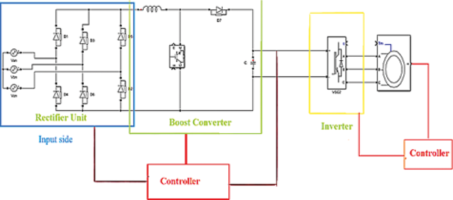
Figure 1: Schematic diagram of the proposed design
In this, the PFC unit offers ripple free and stable power supply to the IM. Each stage is explained in detail below.
The main objective of the AC/DC PFC power supply is to deliver a stable DC supply to the VSI and powers the IM. This stage comprises 3 phase AC voltage, rectifier unit and converter section as shown in Fig. 1. Full wave Diode bridge rectifier is implanted for AC/DC conversion. Conventional Boost DC/DC Converter with PI controller is incorporated to provide supply to IM. The schematic diagram of the proposed converter is depicted in Fig. 2.
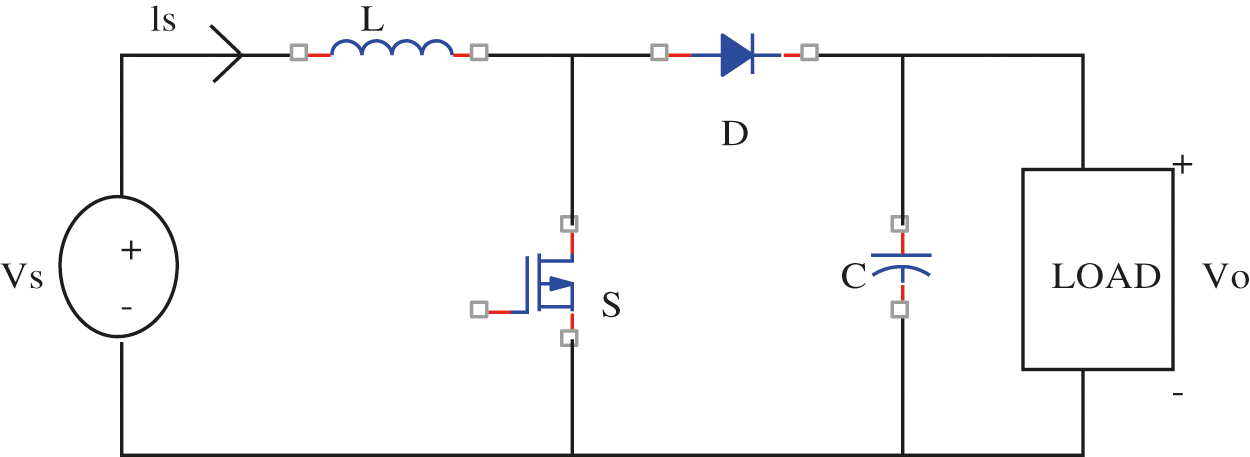
Figure 2: Proposed boost converter
Operation of the converter
Mode-1:
During Mode 1, Switch ‘S’ remains ON and it is shown in Fig. 3a. The voltage across the inductor VL is equal to Vin [23,24].
This can be represented as
Thus, the current across the inductor is about
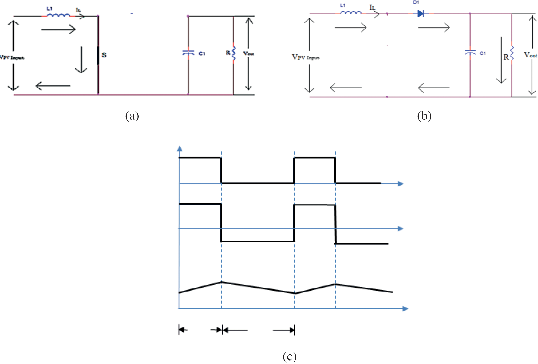
Figure 3: (a) Mode 1 (b) Mode 2 (c) Timing diagram of the proposed converter
Mode-2:
The Switch remains in OFF condition as shown in Fig. 3b. Fig. 3c depicts the timing diagram of the proposed converter.
Under this condition, Vin is about
And the hence the output voltage in terms of duty cycle can be represented as
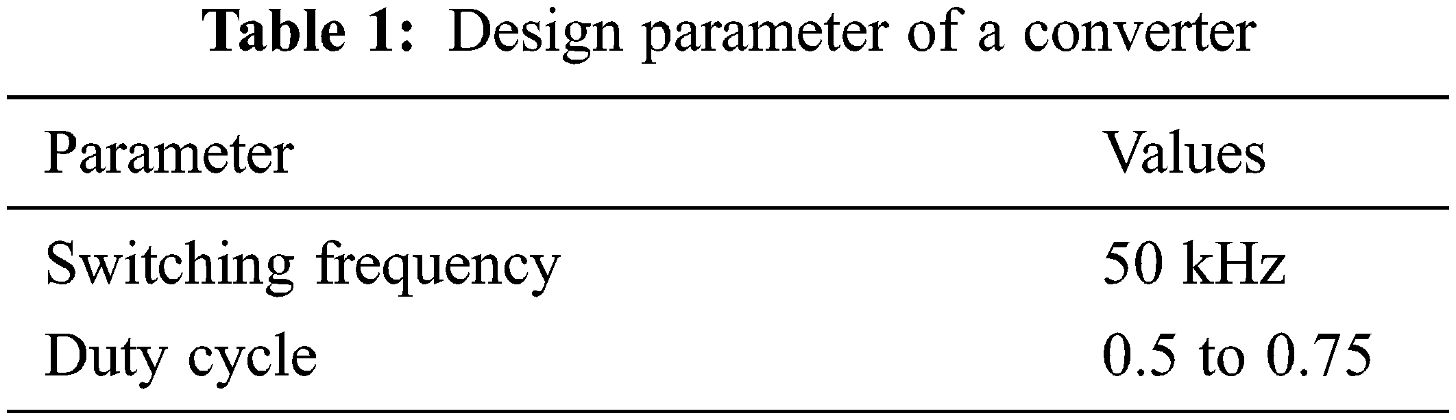
Tab. 1 presents the design inputs used in this converter.
The main aim of the control loop is regulation of dc link voltage. The schematic diagram of a control loop is depicted in Fig. 4a. This control loop controls the output dc voltage. The PI controller acts as controller. The output from the controller activates the PWM (Pulse Width Modulation) signal of the converter.
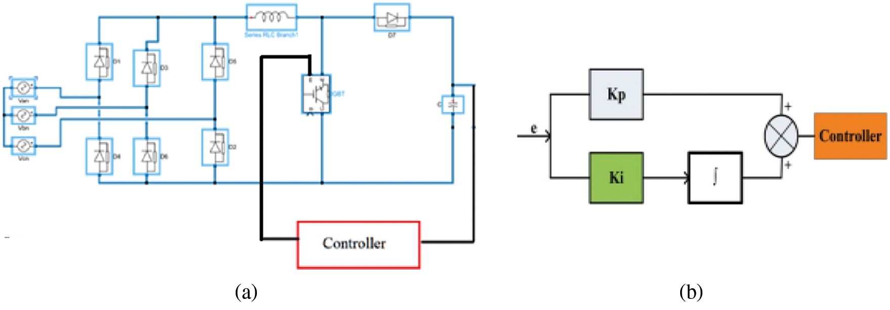
Figure 4: (a) Closed loop control (b) Structure of the PI controller
The standard format of the proposed PI controller depicted below.
where
e - Error
Kp - Proportional gain
Ki - Integration gain
The structure of the PI controller is projected in Fig. 4b.
The output obtained from the converter drives the IM through VSI [25–27]. A Conventional three phase VSI is implemented in this work.
Fig. 5 shows the control of three-phase IM. The speed control over IM is carried out using PI controller. Based on the Gain values G1 and G2, PWM signal is generated for six pulse VSI [28,29]. Here SPWM(Sinusoidal Pulse Width Modulation) topology is utilised for pulse generation.
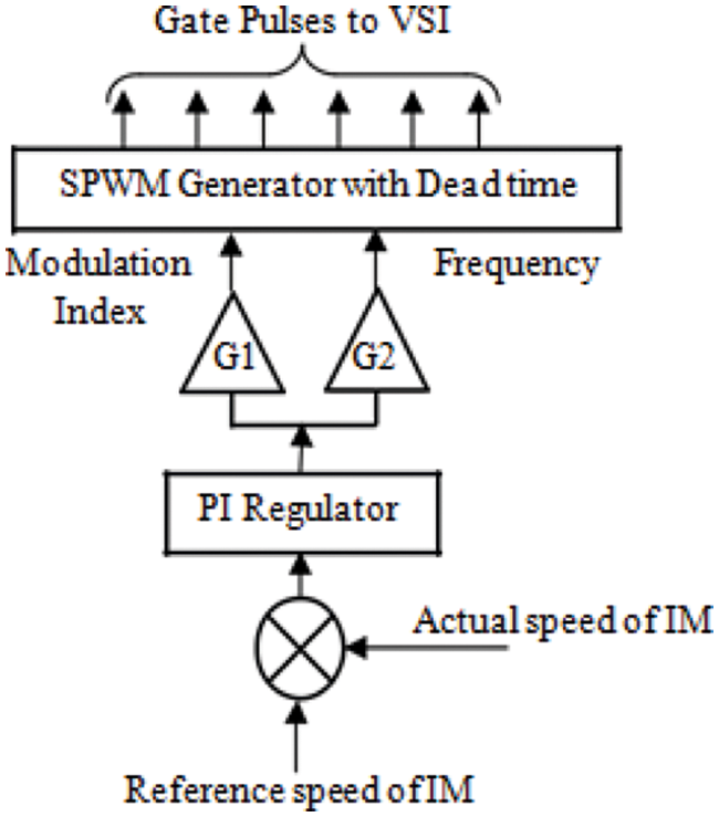
Figure 5: Gate control approach applied to VSI
The effectiveness of the proposed converter was evaluated using MATLAB simulation software. Thus, the performance of the proposed system can be analyzed as follows
Fig. 6 presents a steady state waveforms of the converter. The input voltage obtained from the supply is shown. Fig. 7 presents the output obtained from the converter.
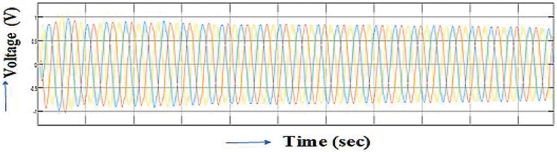
Figure 6: Input voltage of the system (pu)
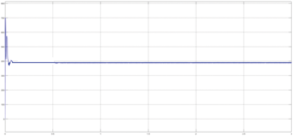
Figure 7: Output of the proposed boost converter
Initially, the capacitor starts charges from zero. When the output voltage of the converter becomes stable (300 V), the motor reaches its steady state condition. As a result the current also remains constant at steady state condition.
Fig. 8 presents the motor stator currents and torque. The motor speed and torque ramp up and reach steady state as seen in the Fig. 8a. Similarly, the output voltage and modulation index of the inverter is depicted in Fig. 8b.
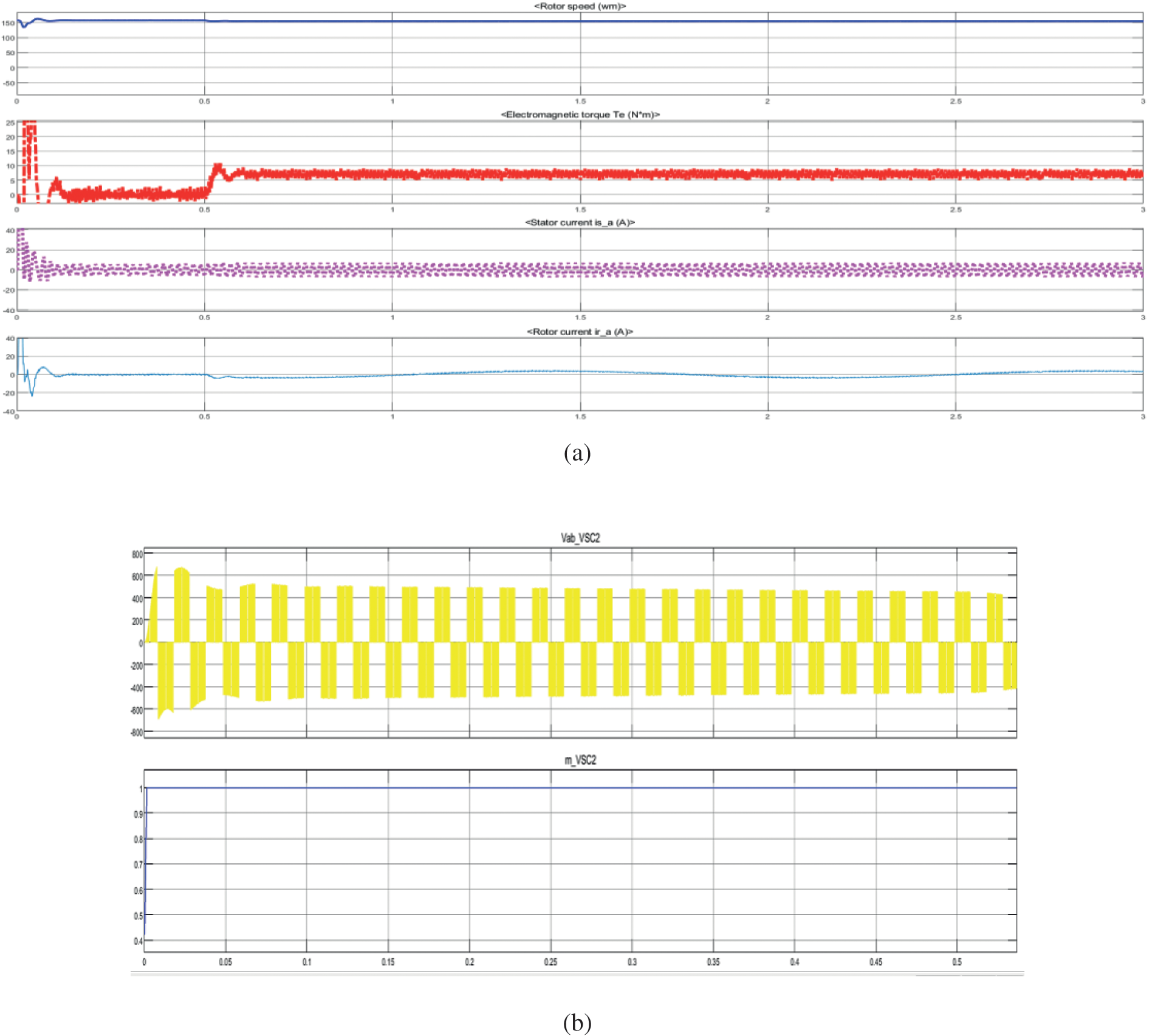
Figure 8: (a) Characteristics of the motor (b) Output of the inverter and modulation index
Thus, to examine the effectiveness of the proposed converter, a prototype model of 3Φ phase IM with full-load torque (7 N.m) is considered and its reference speed is set about 120 rad/sec. Fig. 9 depicts the picture of prototype of proposed converter and its block diagram. The gate pulse given to the switch is generated using dspace board.
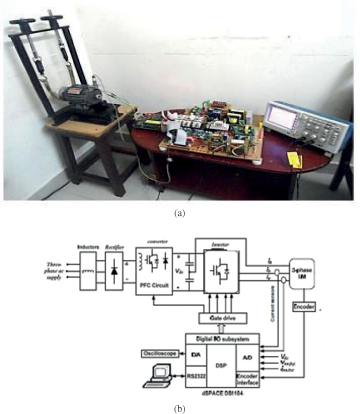
Figure 9: (a) Prototype model of the proposed system (b) Block diagram of the experimental setup
Three-phase supply currents are depicted in Fig. 10. From the Fig. 10, it is clearly observed that the supply currents are nearly sinusoidal and hence, PF is high. DC bus voltage and motor speed are shown in Fig. 11. These values remain same as the reference value.
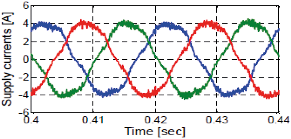
Figure 10: Supply current
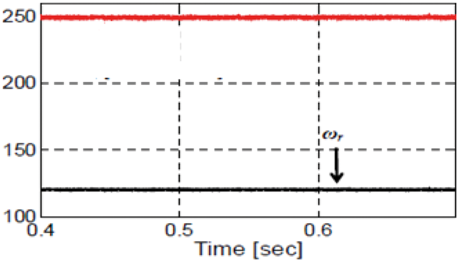
Figure 11: DC bus voltage and motor speed
Tab. 2 shows a comparison analysis with the existing techniques [7,13]. The proposed technique provides cost effective solution and it offers lower THD than the other state of arts. Hence it is concluded that the proposed topology exhibits better performance over power quality issues of adjustable speed drives.
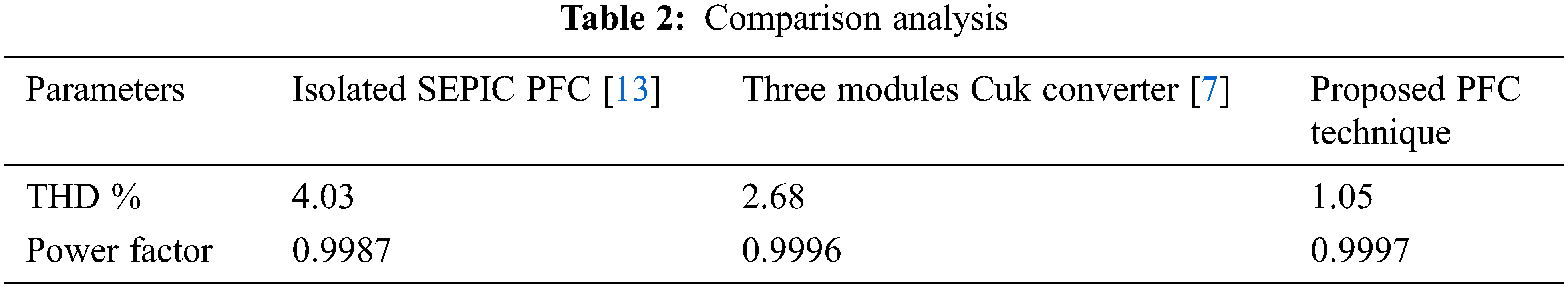
From the obtained results obtained, it is observed that the proposed technique enriches the PF along with the harmonics reduction. Thus, it proves the efficiency of the proposed topology.
A new three-phase PFC for IM drive is modelled and analysed in this work. A PI-controlled boost converter works as a PFC in the proposed system. To deliver power to IM, a traditional VSI is utilized. To regulate the speed of the motor on the inverter side, a PI controller is used. The SPWM topology is specifically designed for the VSI. The suggested system’s performance is verified using simulation and an experimental setting. As a result, the suggested system has a low THD (1.05%) in the supply current, a high input PF about 0.9997 and is simple to construct. In the future, this might be coupled with IoT based controls to provide autonomous control.
Funding Statement: The authors received no specific funding for this study.
Conflicts of Interest: The authors declare that they have no conflicts of interest to report regarding the present study.
1. N. Zabihi and R. Gouws, “Improving energy consumption of an induction motor by design of a power factor correction system and estimation of it’s saving on a large scale,” in Proc. of the IEEE Int. Conf. on Industrial and Commercial Use of Energy (ICUE), Cape Town, South Africa, pp. 1–9, 2014. [Google Scholar]
2. H. Z. Azazi, E. E. El-Kholy, S. A. Mahmoud and S. S. Shokralla, “Power factor correction using predictive current control for three phase induction motor drive system,” Electric Power Components and Systems, vol. 42, no. 2, pp. 190–202, 2014. [Google Scholar]
3. J. O. Estima and A. J. M. Cardoso, “A new algorithm for real-time multiple open-circuit fault diagnosis in voltage-fed PWM motor drives by the reference current errors,” IEEE Transactions on Industrial Electronics, vol. 68, no. 8, pp. 3496–3505, 2013. [Google Scholar]
4. N. Takeuchi, K. Matsui, F. Ueda and H. Mori, “A novel PFC circuit using ladder type filter employing only passive devices,” in Proc. of the IEEE Applied Power Electronics Conf. and Exposition, Austin, TX, USA, pp. 1005–1009, 2008. [Google Scholar]
5. O. A. Ahmed and J. A. M. Bleijs, “Three phase passive bridge rectifier with low distortion input current and boosted DC output voltage,” in Proc. of the 2008 43rd Int. Universities Power Engineering Conf., Padua, Italy, pp. 1–5, 2008. [Google Scholar]
6. U. Kamnarn and V. Chunkag, “Analysis and design of a modular three-phase AC-to-DC converter using CUK rectifier module with nearly unity power factor and fast dynamic response,” IEEE Transactions on Power Electronics, vol. 24, no. 8, pp. 2000–2012, 2009. [Google Scholar]
7. G. Bhuvaneswari, B. Singh and S. Madishetti, “Three-phase, two-switch PFC rectifier fed three-level VSI based FOC of induction motor drive,” in Proc. of the 2012 IEEE Fifth Power India Conf., Murthal, India, pp. 1–6, 2012. [Google Scholar]
8. P. Crisbin and M. Sasikumar, “Analysis of PFC cuk and PFC Sepic converter based intelligent controller fed BLDC motor drive,” in Proc. of the Second Int. Conf. on Science Technology Engineering and Management (ICONSTEM), Chennai, India, pp. 304–308, 2016. [Google Scholar]
9. P. Deshpande, S. S. Mopari and P. S. Swami, “Power factor correction and power quality improvement in BLDC motor drive using SEPIC converter,” in Proc. of the IEEE Int. Conf. on Electrical, Computer and Communication Technologies, (ICECCT), Coimbatore, Tamil Nadu, India, pp. 1–4, 2019. [Google Scholar]
10. Y. Liu, Y. Sun and S. Mei, “A control method for bridgeless Cuk/Sepic PFC rectifier to achieve power decoupling,” IEEE Transactions on Industrial Electronics, vol. 64, no. 9, pp. 7272–7276, 2017. [Google Scholar]
11. D. Wu, R. Ayyanar, M. Sondharangalla and T. Meyers, “High performance active-clamped isolated SEPIC PFC converter with SiC devices and lossless diode clamp,” IEEE Journal of Emerging and Selected Topics in Power Electronics, vol. 8, no. 1, pp. 567–577, 2019. [Google Scholar]
12. U. S. Patel, S. Shiva Kumar and V. S. Kommukuri, “Power factor correction using continuous conduction mode based bridgeless SEPIC converter for improved THD and voltage regulation,” in Proc. of the Int. Conf. on Vision Towards Emerging Trends in Communication and Networking (ViTECoN), India, pp. 1–4, 2019. [Google Scholar]
13. T. Gabriel and I. Barbi, “Isolated three-phase high power factor rectifier based on the SEPIC converter operating in discontinuous conduction mode,” IEEE Transactions on Power Electronics, vol. 28, no. 11, pp. 4962–4969, 2013. [Google Scholar]
14. J. Baek, J. K. Kim, J. B. Lee, M. H. Park and G. W. Moon, “A new standby structure integrated with boost PFC converter for server power supply,” IEEE Transactions on Power Electronics, vol. 34, no. 6, pp. 5283–5293, 2018. [Google Scholar]
15. M. Chomat and S. Ludek, “Compensation of unbalanced three-phase voltage supply in voltage source inverter,” in Proc. of the IEEE, 2002 28th Annual Conf. of the Industrial Electronics Society, IECON 02, Seville, Spain, vol. 2, pp. 950–955, 2002. [Google Scholar]
16. M. Baumann and J. W. Kolar, “A novel control concept for reliable operation of a three-phase three-switch buck-type unity-power-factor rectifier with integrated boost output stage under heavily unbalanced mains condition,” IEEE Transactions on Industrial Electronics, vol. 52, no. 2, pp. 399–409, 2005. [Google Scholar]
17. M. Cichowlas, M. Mariusz, M. P. Kazmierkowski, D. L. Sobczuk, P. Rodríguez et al., “Active filtering function of three-phase PWM boost rectifier under different line voltage conditions,” IEEE Transactions on Industrial Electronics, vol. 52, no. 2, pp. 410–419, 2005. [Google Scholar]
18. X. Guo, H. P. Ren and J. Li, “Robust model-predictive control for a compound active-clamp three-phase soft-switching PFC converter under unbalanced grid condition,” IEEE Transactions on Industrial Electronics, vol. 65, no. 3, pp. 2156–2166, 2017. [Google Scholar]
19. J. C. Basilio and S. R. Matos, “Design of PI and PID controllers with transient performance specification,” IEEE Transactions on Education, vol. 45, no. 4, pp. 364–370, 2002. [Google Scholar]
20. H. C. Chiang, F. J. Lin, J. K. Chang, K. F. Chen, Y. L. Chen et al., “Control method for improving the response of single-phase continuous conduction mode boost power factor correction converter,” IET Power Electronics, vol. 9, no. 9, pp. 1792–1800, 2016. [Google Scholar]
21. W. Qi, S. Li, S. C. Tan and S. Y. Hui, “Design considerations for voltage sensorless control of a PFC single-phase rectifier without electrolytic capacitors,” IEEE Transactions on Industrial Electronics, vol. 67, no. 3, pp. 1878–1889, 2009. [Google Scholar]
22. H. R. Khan, M. Kazmi, H. B. Ashraf, M. Hashir Bin Khalid and A. Hasan, “An isolated power factor corrected cuk converter with integrated magnetics for brushless dc ceiling fan applications,” Electronics, vol. 10, no. 14, pp. 1720, 2021. [Google Scholar]
23. D. Sun, J. Su, C. Sun and H. Nian, “A simplified MPFC with capacitor voltage offset suppression for the four-switch three- phase inverter-fed PMSM drive,” IEEE Transactions on Industrial Electronics, vol. 66, no. 10, pp. 7633–7642, 2018. [Google Scholar]
24. H. Z. Azazi, S. M. Ahmed and A. E. Lashine, “Single-stage three-phase boost power factor correction circuit for AC-DC converter,” International Journal of Electronics, vol. 105, no. 1, pp. 30–41, 2018. [Google Scholar]
25. S. Sajeev and A. Mathew, “Novel cost effective induction motor drive with bridgeless PFC and four switch inverter,” in Proc. of the 2013 Int. Conf. on Emerging Trends in Communication, Control, Signal Processing and Computing Applications (C2SPCA), Bangalore, India, pp. 1–6, 2013. [Google Scholar]
26. M. Gonzalez-Ramirez and C. A. Cruz-Villar, “Variable speed drive with PFC front-end for three-phase induction motor,” Electronics Letters, vol. 53, no. 16, pp. 1139–1140, 2017. [Google Scholar]
27. M. Chomat and L. Schreier, “Power factor correction in voltage source inverter under unbalanced three-phase voltage supply conditions,” in Proc. of the 2003 IEEE Int. Sym. on Industrial Electronics (Cat. No. 03TH8692), Rio de Janeiro, Brazil, pp. 264–269, 2003. [Google Scholar]
28. B. El Badsi, B. Bouzidi and A. Masmoudi, “DTC scheme for a four-switch inverter-fed induction motor emulating the six-switch inverter operation,” IEEE Transactions on Power Electronics, vol. 28, no. 7, pp. 3528–3538, 2013. [Google Scholar]
29. J. Klima, “Analytical investigation of an induction motor fed from four-switch VSI with a new space vector modulation strategy,” IEEE Transactions on Energy Conversion, vol. 21, no. 4, pp. 832–838, 2006. [Google Scholar]
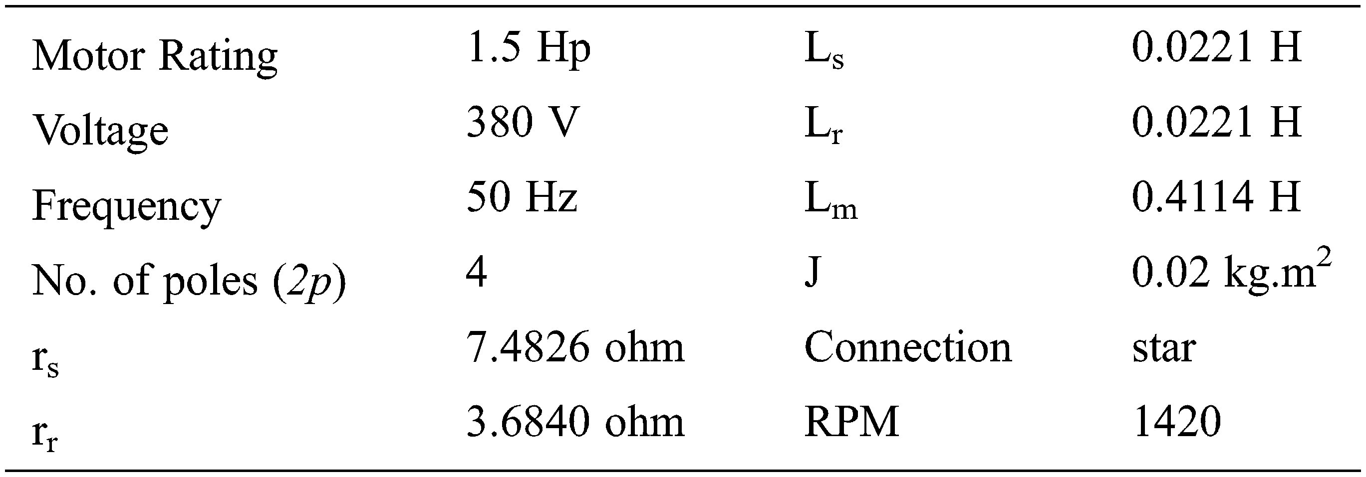
Nomenclature
Appendix A
Induction Motor Rating
 | This work is licensed under a Creative Commons Attribution 4.0 International License, which permits unrestricted use, distribution, and reproduction in any medium, provided the original work is properly cited. |