DOI:10.32604/iasc.2022.025860
| Intelligent Automation & Soft Computing DOI:10.32604/iasc.2022.025860 | |
| Article |
Analysis of Brushless DC Motor Using Enhanced Fopid Controller with ALO Algorithm
1Department of Electrical and Electronics Engineering, Sri Sai Ram Engineering College, Chennai, 600045, Tamilnadu, India
2Department of Electrical and Electronics Engineering, College of Engineering, Anna University, Chennai, 600025, Tamilnadu, India
3Department of Information Technology, Sri Venkateswara College of Engineering, Sriperumbudur, 602105, Tamilnadu, India
*Corresponding Author: K. Prathibanandhi. Email: kprathibanandhi@gmail.com
Received: 07 December 2021; Accepted: 14 January 2022
Abstract: The delivery of combined benefits of Alternating Current (AC) motor and Direct Current (DC) Motor makes the Brushless Direct Current (BLDC) motors as a unique feature in numerous industrial applications. The possibilities of running the motor at very high speed with extensive operating life span of BLDC with miniature and its compact design make it an un-ignorable option for Electrical Engineers. With many advantages, till managing as well as controlling the speed of BLDC is complicated. This work is intended to come up with an effective control of speed of the motor through Torque Ripple Minimization Route and an Enhanced-Fractional Order Proportional Integral and Derivative Controller based Ant-Lion Optimizer (EFCA)Technique, which is evaluated as well as its strategy is executed in this paper. The critical factors like BLDC’s Back Electro Magnetic Force, Values of Current, Torque level and the operating speed of the motor are considered and evaluated closely and from that, the ripple level present in the torque is controlled as well as it is brought down to minimalistic value by using Fractional Order (FO) Proportional Integral Derivative (FOPID) controller. To control the speed of the motor, the Gain parameters and the ripple present in the torque have to be reduced, the latter is obtained using FOPID controller and the former is achieved by employing Modified – Ant Lion Optimizer (ALO). The technique presented in this paper helps for the enhancement of controlling behavior of BLDC and improves the overall performance of the motor. The dynamic part of the BLDC is analyzed using the platform of Matrix Laboratory (MATLAB) simulink and the results are tabulated. The final values are compared with the results of the existing methodologies and the comparative study has yielded that the presented technique has outperformed than that of the available methodologies. A proto type model has been designed and results are executed in real time environment to ensure the effectiveness of the presented work.
Keywords: FOPID controller; BLDC motor; ALO algorithm; BA; PSO; speed; torque ripples
In this era of industrial revaluation, the commercial industries need electrical motors which have less complicated design structures with high power density, wide spread of T (Torque) to I (Current) ratio and maximum possible speed with optimal control of the same. The Direct current motor of Brushless type (BL-DC) possesses all the said qualities and hence, it is being obvious choice in the modern industrial applications as well as this BL-DC motors have no brushes and commutator in their design structure which makes it peaceful to use in all kinds of medical related, and domestic applications [1–3]. The brushless motor of DC type has permanent magnets in its construction and the permanent magnets are placed either interior of stator body or mounting it on the surface where the latter is called as out-Runner BL-DC and the former is called as In-Runner BL-DC [4–6]. In order to achieve precise position and accurate running stages in brushless type Direct Current motors, proper regulation of speed and position is pre-requested and if it is placed in the operations where it requires sensible speed and position. When the motor of BL-DC types operated in a condition of steady state, visible increased flections, and transitory periods in the form of large overshoot occur as a result of speed of the motor.
The highly concerned factor, which restricts BLDC’s placement in highly precise applications, is its non-ideal trapezoidal shape back- Electro Magnetic Field (EMF) and Non-idealistic of phase current at commutation which happen because of the existence of the ripple content in BL-DC motor’s Torque, since these parameters effectively de-stabilize the motor action. There are some of the few results, why the researchers are more concern about minimization of ripple presence in BL-DC motor torque [7–10]. There are many factors being the reason for creation of ripples in the torque of BLDC motor, specifically, imperfections in the stator part including all kinds of controlling units, usage of power electronic components with high frequency operating ranges and also the presence of harmonics in the input supply voltage of the motor. Commutation using electronic means as well as the pulsating inputs current indirectly induces the ripples in the torque [11–13]. In order to achieve better performance, a suitable controlling technique with proper methodology is needed to eradicate or minimize the existence of the ripples content in BL-DC motor torque either through regularizing the line voltage pulsating nature and or eliminating the presence of harmonics in the line supply (voltage) of the Drive of the BL-DC motor [14,15]. An optimal control of Torque is a method adopted in BLDC motor drive control system and this technique helps in reducing certain level of ripples in the torque [16] like that many more technologies have been implemented and intended to overcome the ripple reduction issues in the BL-DC motor torque specifically PWM: Pulse Width Modulation scheme, change of phase using Overlap method [17], current control using prediction technique, Direct control of Torque and Hysteresis method (Current) but in those techniques either under compensation or Over compensation problem exists that nullifies the effect of the technique used in the minimization of ripples content in motor torque [18–20]. The control methodology and technique need to estimate current running count of rotor and its slot position need to be known before applying any technique that involves in minimization of ripples present in BLDC motor torque. For this purpose, some kind of estimation based analysing technique or placement of sensor on the rotor is used to do the task [21,22]. Many topologies have been presented to control the speed of the DC motor such as P-I : Proportional Integral which makes the native impact of PI (that is High Rise Time, Huge Fall Time or settling time and possibilities of oscillation) and it is not an oblivious choice for BLDC motor speed control mechanism [23]. Apart from Genetic Algorithm (GA), Neural Network (NN), Least Square Approximation (LSAM) and Improved Gradient Descent Algorithm (IGDA) are some of the conventional algorithms used in the motor control mechanism [24,25].
The speed management with torque improvement in the form of reducing the presence of ripple content has become the hinting stone for many researchers and they have come up with many techniques, topologies and design procedures. Some of the recent works related to the speed management with torque improvement are reviewed in this section. ANFIS: Adaptive Neuro-Fuzzy Inference System framework for brushless Direct current motor speed management. Extensive simulations are performed on the MAT Lab tool with help of simulink feature and they have compared the performance of the system with help of traditional controllers like Proportional Integral (P-I), Proportional Integral Differential (P-I-D) along with Fuzzy Variable Structure (FVS) [26]. The time varying nature of the BL-Direct Current motor is examined. Specifically, factors such as time taken to Rise, Time duration utilized for complete recovery, Error at steady state, under and Over Soot are noted for the BL-DC motor while applying the controlling technique. The simulations have been done for the scenarios like different loads and varying running conditions of the motor. The speed management using P-I-D based controller by utilizing PSO along with Bacterial Foraging (BF) [27].
For the parameter management, P-I-D controller is used in BL-Direct Current Motor drives to handle the speed of the motor, Error at steady state, Maximum Over shoot, time taken to Rise, Time duration is utilized for complete recovery as well as step response is handled considerably by this technique which has missed to address the existence of the ripple content in the Torque of BL-DC motor. Calculations of Phase to phase trapezoidal back-EMF without using any sensing element [28]. They have modeled most challenging task like tactical design and analysis for high performance of BL-DC motor without using any sensor. They have named the technique as De-convolution and they have developed a Filter by setting it at H-infinity. Hence, it is called as robust stochastic H-infinity de-convolution filter. Generally, the approach followed in handling Back Electro Motive Force in Brushless Direct Current Motor Drive is observer monitoring based and the factor Back Electro Magnetic Field (B-EMF) is considered as ‘Unknown Value’. In contrary, the authors have tried to include the modeling of this parameter, since in the tradition monitoring based technique, Back Electro Motive Force is ignored to estimate in the continuous and frequent interval and it leads to high presence of ripple in the motor torque because of the position of the rotor slot and variations in the running count [29]. The variation of running count and position of the rotor induce high Back Electro Motive Force, since it is dynamic in nature with the cumulative effect and the ripples present at the Torque (Commutation) increase rapidly. To handle such scenarios and attain high precision speed management, the authors have proposed a Direct Torque Control method (DTC-m) into a 3 phase 120 conduction angle BLDC motor to compensate the downgrade factors, but this technique has failed to achieve considerable improvement in the overall motor performance. The high performance delivering DTC has been re-modified [30]. They have used high quality Insulated Gate Bipolar Transistor to handle higher and lower frequencies of the employed inverter module. This simple modified DTC: m-DTC has helped the system to achieve extended performance with improved overall system reliability. The 3 stage torque (Hysterias) controller helps the system to achieve better speed control by minimizing the existence of the ripple content in the torque [31].
The major objective of the proposed work is to come up with an effective control of speed of the motor through Torque Ripple Minimization Route and an Enhanced-Fractional Order Proportional Integral and Derivative Controller based Ant-Lion Optimizer (EFCA)Technique.
The organization of this research manuscript is proceeded as Literature study in Section 2 with a detailed illustration on BLDC motor modeling in Section 3. The proposed technique is described in Section 4 with an analysis of simulation results in Section 5. The work was concluded with future scope in Section 6.
3 BLDC Motor Modeling and Design
The stator and rotor design of the Brushless Direct Motor is a machine which interchanges the applied Electrical Input into an equivalent Mechanical Movement by means of permanent magnet created with Magnetic field. The performance and the management of motor including speed depend on the position of its rotor slots. Trapezium and sinusoidal are the two important methods of forming a coil structure (Stator; - Non Movable Part of the motor) which is generally termed as Windings. Normally, all the windings of the BL-DC motor are interconnected. Both the stator and Rotor (Movable part of the motor) have windings and hence, Back electro Motive Force is emerged because of the windings on the stator. Brushless Direct Current Motors have three crucial aspects: connected load and speed, pulse width modulated inverter power conversion and current and torque controller. In that, trapezoidal back-EMF has very high power density and less complicated speed and torque control method. Hence, based on this factor the design of BL-DC is widely adopted. Further, the design based on this method requires single direct current linkage to perform the task of allowing current to flow in two phases of the motor smoothly out of three phases on the motor. The stator is designed with non-permanent type of magnet while the rotor is designed with a permanent magnet, since the characteristics keep vary during operation (Dynamic – Characteristics). The 3rd phase of the motor is in OFF state, since the connected inverter with the BLDC has only 2 terminals and hence at any given time, two phases out of three are always connected with the inverter and the remaining one phase always in OFF state. In common practices, the controlling signal is generated using Pulse Width Modulation based or Hysterias based from the Microcontroller through the available option of control modes either Torque or Speed and the symmetrical framed 3 Φ BLDC. Its current equation is listed via Eq. (1) and Voltage equation of the same is listed in Eq. (2).
In Eq. (2), ‘U’ is used to indicate the windings of the stator and ‘I’ (in Amphere) represents its corresponding current values. Subscript ‘A, B and C’ help to identify the phases of the motor. The Electro Motive Force is resulted due to backward which is represented via E (In Volts). The Neutral point is indicated using the notation U. s &
3.1 Intend of Back Electro Motive Force and Torque Generation for BL-DC Motor
In Brushless Direct Current Motor, permanent magnets are used in the rotor fabrication which in turn during operation cuts the windings of the fixed stator. As a result, a voltage will be induced on rotation and it is in the opposite direction to the line voltage. Hence, it opposes the line voltage force which is referred as Back Electromotive Force (B-EMF) and it is influenced by the following factors (1) strength of the Magnetic field (permanent magnets of the rotor field strength (2) winding counts of the stator (Number of turns) and (3) rotor’s Angular Velocity. During the operation of the BL-DC motor, the Electro-Mechanical Torque produced is represented by using the Eq. (3),
In the above Eq. (3), the terms used as same meaning as represented in Eqs. (2) and (1) except that
Here, the notation
The rotor’s slot movement (in Angular Fashion) is derived based on Newton’s second law of motion and it is given by Eq. (6).
In the above Eqs. (5) and (6),
In the complex structure of Brushless Direct Current motor shows extreme complexity in the management of speed and torque control during running condition. The Voltage Source Inverter used in the BLDC motor drive requires high frequent switching which causes instability issues like increased vibration of the motor and contributes to switching losses. Moreover, the hysteris of line voltage and various torque creating complexity design procedures of BL-DC induce the creation of ripples in the Torque of the motor. It leads to uncontrollable speed and the torque management makes it less suitable to precision applications. Many protocols and methodologies have been presented to address the issue and till the exact optimized performance with perfect speed and torque management for BLDC has not been witnessed. This paper addresses the issue by presenting an EFCA (Proposed) Technique and the complete methodology of the technique is detailed in the following sections.
4 The EFCA (Proposed) Technique
To improve the performance of the BLDCM Drive, more focus should be given to speed management and control strategies for Torque. These two mechanisms are possible by eliminating and or minimizing the existence of the ripple content in BLDC motor drive. In the presented controlling strategy, the gain parameter of the BLDC is taken as key element to achieve the intended results. FOPID controllers used in this technique need an optimized gain parameter to achieve the intended results and it is done through modifying the Ant Lion Optimizer Algorithm. This Modified – Ant Lion Optimizer (M-ALO) takes care of Speed/Error Loop regulation of the FOPID controller which in-turn helps in the minimization of ripple content present in the Torque of BLDC indirectly and hence, the performance of the system is improved. It is clear that VSI used in the process receives Direct current linking voltage from the rectifier and it ensures perfect line voltage, since the rectifier is fed by the line voltage as well as it feeds the BLDC depending on load connections. In this arrangement, the angle of commutation of BLDC is connected internally in order to regulate the operation of the motor, since the rotation of the slots of the rotor is handled by commutator. Hence, the rotation becomes smooth and proper and also the commutator plays of the generation of B_EMF, even though speed of the BLDC purely depends upon the amplitude of the supply voltage which is controlled by using Pulse Width Modulated signal. Through the proposed EFCA (Proposed) technique, the control of speed management is achieved and through which, the presence of the ripples is minimized in the BL-DC Motor Drive. The performance of the presented Modified ALP with FOPID controller is witnessed by analyzing the following strategy of this system in a detailed way.
4.1 Strategy Used by EFCA for Speed Control of BL-DC Motor
The BLDC’s Rotor slot placement within the motor complex structure is linked with Rectangular Voltage which in turn drives the BL-DC Motor. The Fig. 1 explain the control strategy used in the proposed system.
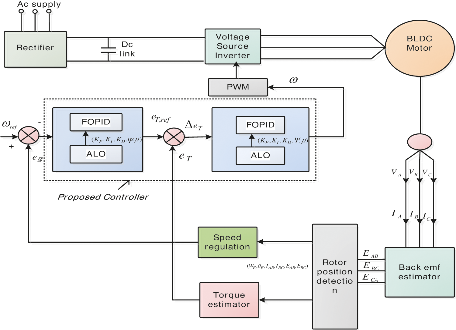
Figure 1: Control strategy used in EFCA technique
Inside the BLDC structure, Stator and Rotor Fluxes meet together, since the rotor flux is fixed due to permanent magnet and stator is flux based on the supplied voltage. The rotor magnets play vital role, since the speed and torque of the motor depend on these magnetic fluxes of the rotor. From this angle, it may be convenient and in the beginning, management of speed of BLDC is examined by using this presented mechanism. All kinds of Errors at speed management are managed using the presented controller, since by comparing with the pre defined parameter, the running count of the BLDC is estimated and it is displayed using Eq. (7).
The presented FOPID controller is fed with the comparator output as a input, since the comparator gets the values as per the Eq. (7) that is the error at speed and it is obtained from the comparator output as per the design of this EFCA (Proposed) Technique. The core benefit of EFCA is the gain optimization which is done through modified Ant-Lion Optimizer algorithms which effectively handles and optimizes all the five gain parameters of the controller (FOPID). Further, the parameter (gain) of controller (FOPID) plays effective role in handling the FOPID controller during operation. These Gain values are accurately tuned by the way to achieve the best outcome from the controller. These are the steps involved in this presented system to estimate the final Error in the resulting Torque values and they are detailed in the forth coming section.
4.2 Strategy Used by EFCA for Torque Control of BL-DC Motor
The second target of this EFCA (Proposed) Technique is elimination or minimization of the presence of ripples in the BLDC motor torque in order to achieve better performance. The ripples content exists at Torque in the commutator (Commutator Torque) due to the motor running at high speed and to handle this scenario, Torque ripples are created when the motor is running at high speed and it is effectively handled by Direct Control Strategy (DTC) which is an effective mechanism to remove the existence of ripple content at high speed in BLDC motor by utilizing EFCA (Proposed) Technique algorithm. The Controller developed by EFCA (Proposed) Technique generates necessary reference values for the 3 phase BL-DC motor drive and it is being the first input to the comparator. Whereas the original torque value from the real-time operation is fed as the second input to the comparator. The comparator now generates change in Error values on the top of the proposed Optimization strategy. The PWM which generates the actual controlling pulse for the proposed controller generates the final optimized value as a control signal to the proposed FOPID controller. This approach of EFCA nullifies the need of effective calculation and accurate feed of line voltage to the controller, since the Torque due to EMF of the BLDC motor stays stable and also due to the effect of this EFCA algorithm, the creation of ripples in the commutator torque is minimized. As the speed of the motor is stable, switching losses are minimized even at high speed running condition of BLDC motor drive
4.3 EFCA’s Strategy to Control BL-DC Motor Using FOPID Controller
EFCA (Enhanced-Fractional Order Proportional Integral and Derivative Controller based Ant-Lion Optimizer) methodology utilizes an Enhanced version of FOPID controller in order to manage the speed control of the BL-DC motor as well as to get hold of the Torque management of the motor. It is depicted in Fig. 2. The Brushless Direct Current Motor’s reference current is kept as an extract in order to enhance the FOPID controller used in the EFCA technique. Similarly, the extract of the Error value at motor speed, when the line voltage is intact, is also utilized to enhance the intended FOPID controller presented by EFCA. The speed (reference) is used in the comparator to evaluate the error at speed from the line voltage of BL-DC Motor drive. The speed error
Here, the speed controller (FOPID) output is indicated using
Eq. (8) explains the Transfer Function of the Enhanced FOPID controller proposed by EFCA technique and in similar way, control Loop for Torque in BL-DC motor intended by EFCA is written as follows in Eq. (9).
Here, the EFCA’s Enhanced FOPID controller’s torque output is indicated using
In the EFCA’s Enhanced FOPID controller operation, all the five gain parameters namely
5 Simulation Outcome and Discussions on Prototype
The presented EFCA (Proposed) Technique’s simulated view is illustrated in Fig. 2 and it is then coded and run through using MAT Lab simulink tool on the windows Environment with the core objective of eliminating or minimizing the presence of the ripple content in the BL-DC motor Torque and achieving the best management of speed. The entire necessary factor needed to prove the effectiveness of this EFCA system for achieving the said target is obtained in form of graphical representation. The obtained values from this simulation are then compared with the existing methodologies in order to understand its effectiveness.
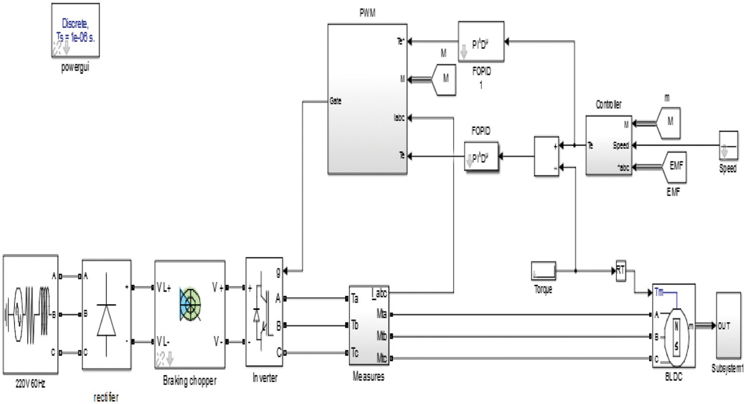
Figure 2: View of the simulated model of EFCA
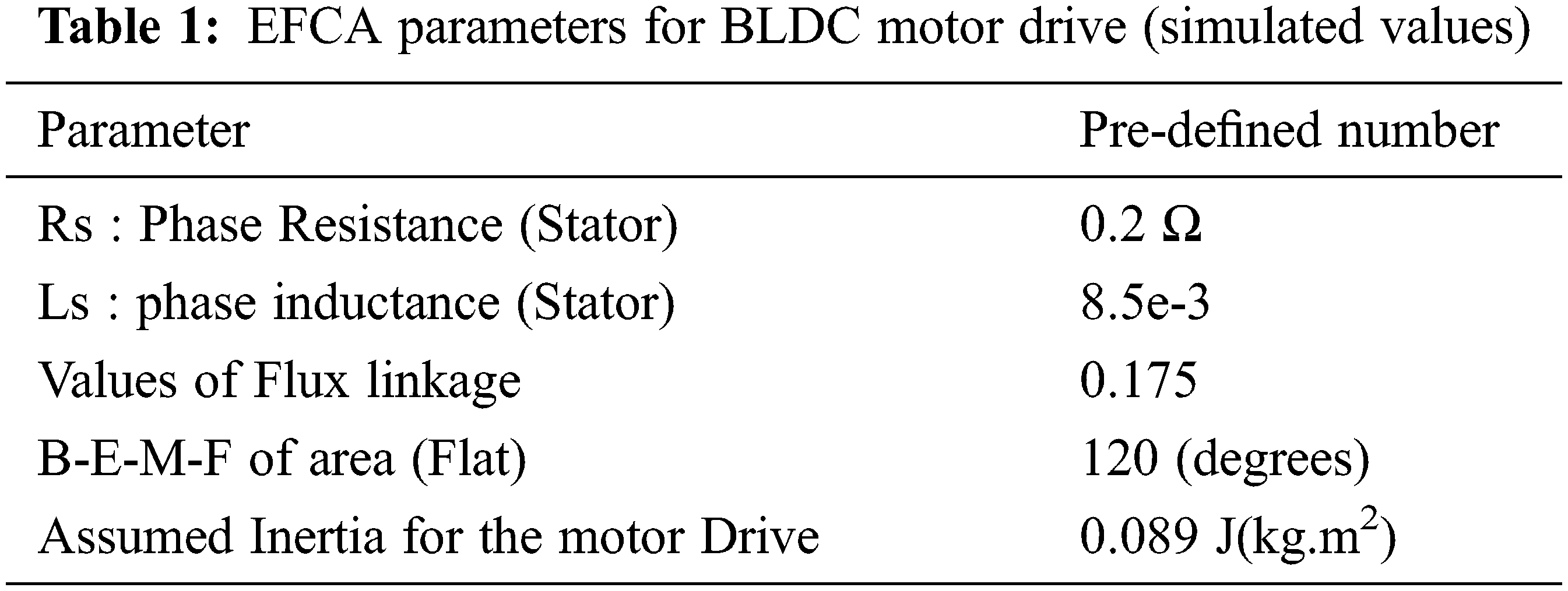
The parameter values are utilized for the purpose of understanding the performance of the presented system. Tab. 1 elaborates the simulation values utilized for the above purpose. By varying the speed reference parameter, three scenarios are tabulated namely (i) 500 is kept as BLDC Motor Drive reference speed (ii) 700 is kept as BLDC Motor Drive reference speed and (iii) 1000 is kept as BLDC Motor Drive reference speed. The outcomes of these three scenarios are discussed in detail.
5.1 EFCA (Proposed) Verses Existing Methodologies
The outcome of the EFCA (Proposed) Technique’s simulated version values are compared with the existing methodologies to prove the efficiency of the proposed approach. In that connection, the proven algorithms like Particle Swarm optimization (PSO) and BAT algorithms are taken as base models and the outcome of EFCA (Proposed) Technique is taken as an ALO Notation. In the first comparative analysis, the Torque of BLDC motor is taken and the EFCA (Labeled as ALO in the graph) and the existing methodologies are labeled as PSO and BAT in Fig. 3.
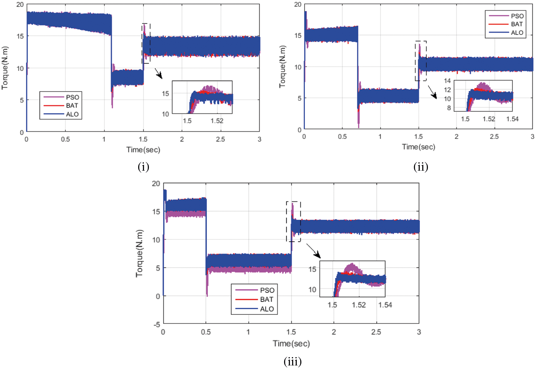
Figure 3: (i): Parameter - Torque in Incident I (ii): Parameter - Torque in Incident II and (iii): Parameter - Torque in Incident III
The analyses are helpful in determining the performance of the methodologies and before the detailed comparative study, the speed of the BLDC motor drive depends on the parameters (input), through which the desired controlling mechanism is excised. Figs. 4(i)–4(iii) explain how the speed management is handled by the three technologies for all the three incidents that are listed. The most impacting time duration is 1.4 s (after the start of the simulation from ‘0’ s) and it is measured up to 1.52 s where all the minute details are captured for analysis purposes. The simulation results suggest that at different time duration as well as continuous varying of speed scenarios, the presented EFCA (proposed) intruded Enhanced FOPID controller has outperformed all the existing methodologies
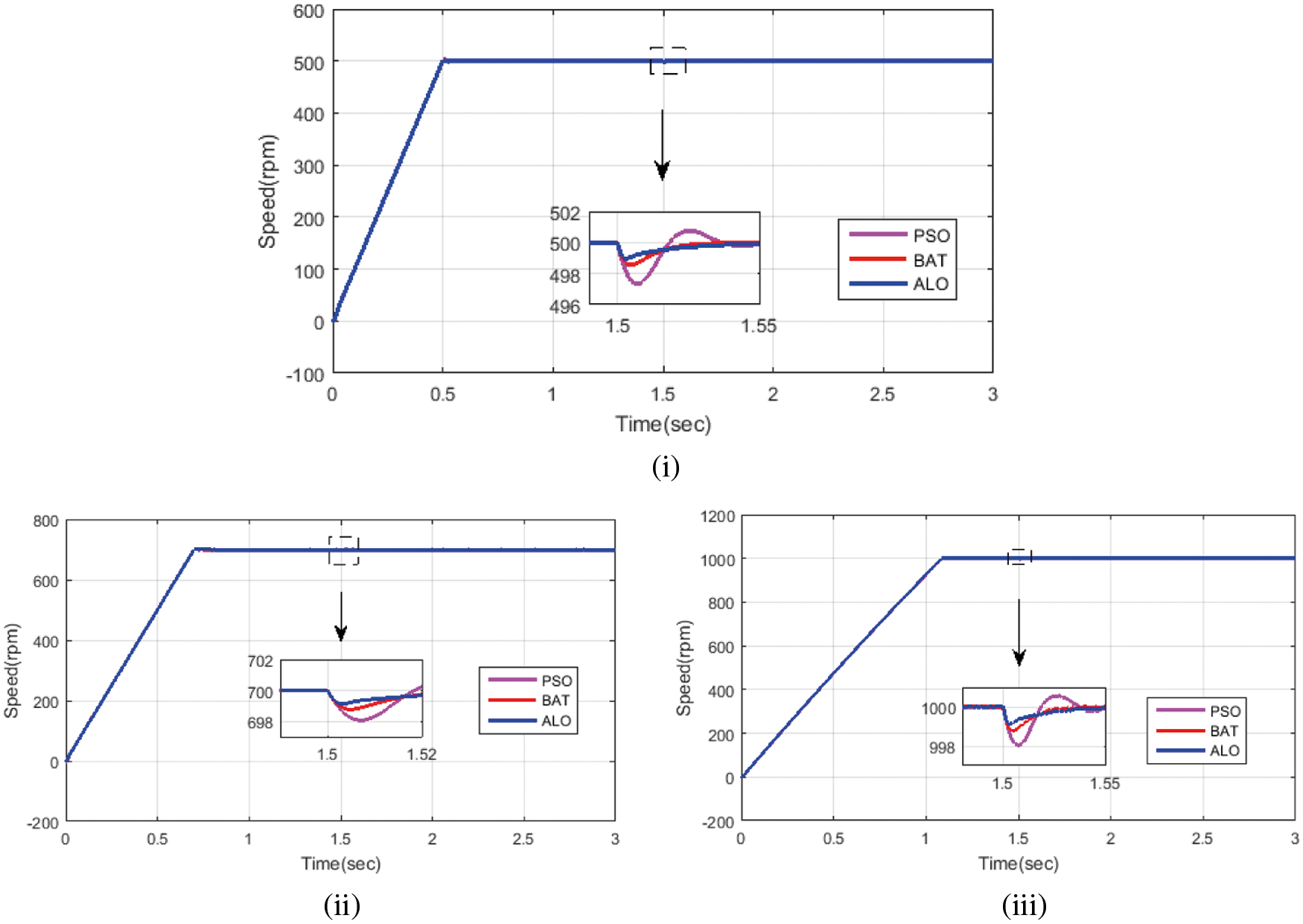
Figure 4: (i): Parameter - Speed in Incident I compared with existing methodology (ii): Parameter - Speed in Incident II compared with existing methodology (iii): Parameter - Speed in Incident III compared with existing methodology
It is clearly analyzed motor at slow speed and motor at medium speed considers the BLDC at maximum speed as well as the speed is influenced by the torque of the corresponding BLDC motor. The ripple creation in the torque visualized in the speed of motor and speed management is dragged. Similarly, any variation in the speed of the working BLDC motor negatively impacts the torque of the motor and leads to the creation of ripples in the torque of the motor. The fig. representing torque performance of the intended EFCA (Proposed) technique displays very minimal creation of ripples in the motor torque compared to the existing methodologies and it can be identified. The presented EFCA (Proposed) methodology has proved to be efficient in reducing the torque ripple content and achieved stable management of speed as well as helps to improve the overall performance of the BLDC Motor. In addition, the following parameters like settling time, rising time and overshoot time of the of the intended EFCA technology have been recorded and examined. In case 1, the rising time, settling time and overshoot time are 0.003, 1.13 sec and 0 sec, respectively by using the proposed technique. While using Bat and PSO algorithms, they are 0.6, 0.8, 0, 0.5, 0.4 and 0 s, respectively. At the same time, the torque ripples of the proposed system are reduced compared to the existing methods. Hence, the proposed method achieves less rising time, settling time and overshoot when compared to the other techniques. It can be noted that Tab. 2 depicts the outline of the decrease of torque ripples under the speed varieties under three case conditions. At first, the working rate is considered as 500 rpm and the different strategies of BAT, PSO, and the proposed calculations are broken down to reduce the torque ripples. Whereas in the EFCA (Proposed) technique, the calculation is used to further develop the torque deviation that is contrasted with the BAT and PSO calculations for example, 4.9% and 6.75%. Furthermore, the speed is viewed as 700 rpm; likewise, the proposed procedure of the ALO calculation is further developed and the torque deviation is contrasted with different techniques like BAT (2.25%) and PSO (2.48%).
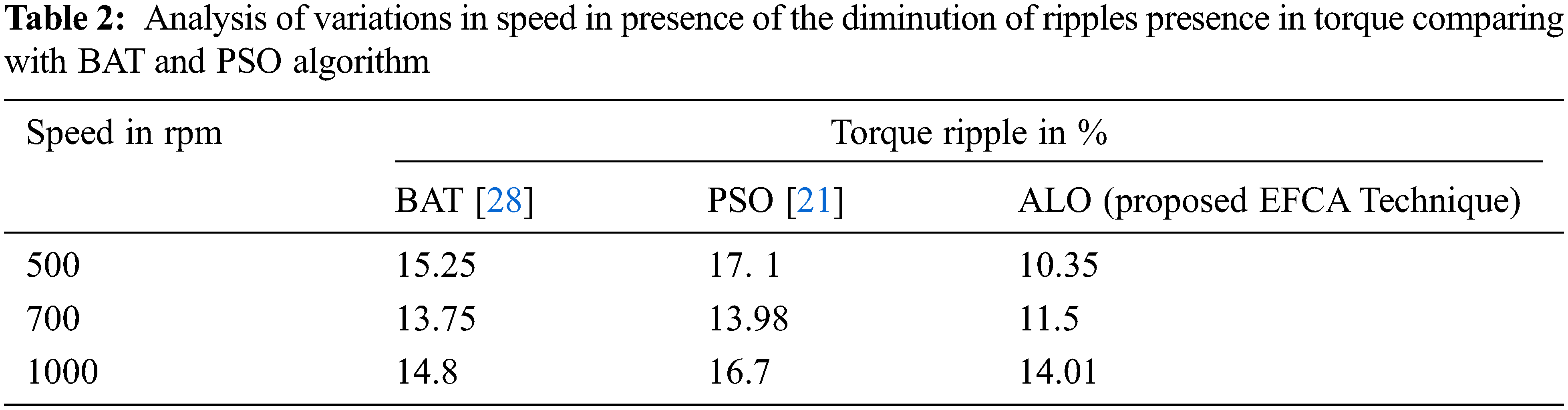
Also, the speed is considered as 1000 rpm; the level of the force swell is diminished in the proposed strategy when contrasted with the existing methods and they are 0.79% and 2.69%. The investigation and the correlation clarify that the viability of the proposed framework is superior to the existing procedures like PSO and BAT calculations. In this regard, the proposed method is used to limit the Torque waves of the BLDC motor. Then again, the current strategies have been examined to decrease the torque ripples and to prove the predominance over the proposed techniques from a calculation intricacy boundary tuning perspective. Taking everything into account, the projected control framework works on power and the precision of the driving plot is with the surge of more computational complexity and correcting some more supplementary parameters which are associated with the conventional approaches.
The performance of any simulated system has to be effective in real time applications. With the view of the proposed EFCA Technique, real-time feasibility is examined in this section. For this purpose, a proto type model for EFCA technique has been developed. To give much more clarity on the designed proto type for EFCA, a line diagram is also included in Fig. 5. For the proto type model ATSAMD21G18 ARM Cortex MO processor, the VSI used in the process directly gets the connection from a 48 Volts Direct Current battery based power supply and it is fed with the required supply of the BL-DC motor drive. Digital Oscilloscope is used to execute the simulated version of EFCA (Proposed) Technique in real-time environment. The B-EMF generated in this prototype is helpful in determining the required parameters like torque status of the motor and position of the slots (Rotor) at every 60 degree angle. By managing the PWM to generate the required controlling pulses, the required improvement of the system is achieved. The Fig. 5a gives the insight about line voltages and direct current linking voltage details and its corresponding speed performance of the BLDC motor is depicted in Fig. 5b. In this incident, the raising time is lasted at 0.2 s whereas the settling time of the motor has taken around 1.08 s Similar values are noted when the motor runs at medium speed (750 RPM) and Maximum Speed (1000 RPM) as explained using Incident I, Incident II and Incident III, and are depicted in Fig. 6.
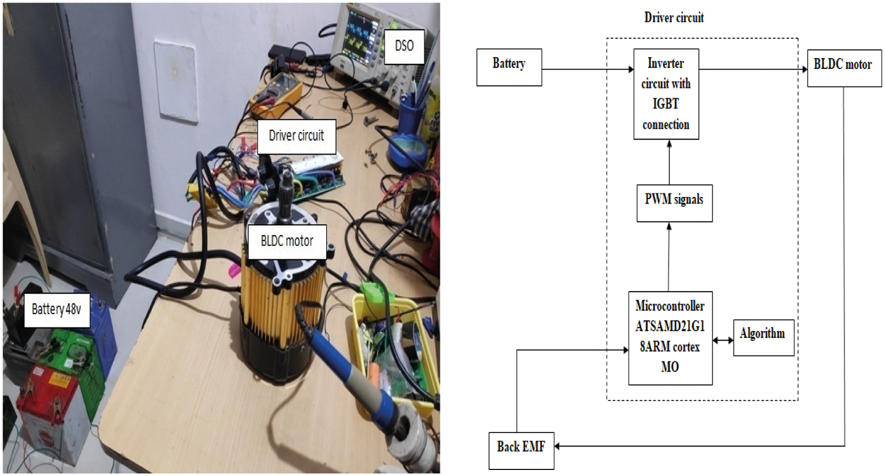
Figure 5: Developed model for EFCA (proposed) technique
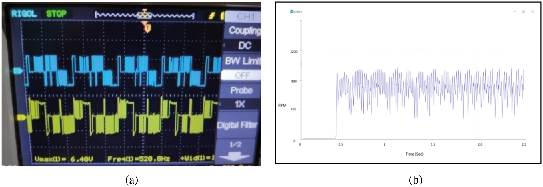
Figure 6: (a): Line voltage of EFCA techniques proto type when 750 RPM (b): Speed of EFCA techniques proto type at 750 RPM (medium BLDC motor speed)
This work has elaborated the proposed system of EFCA (Proposed) technique for the speed management of BLDC motor drive and provided a path to the minimization of ripple contents in the Torque of the motor as well as it greatly influences the controlling activities of the BLDC motor drive. The examinations are done by running the motor at various speed and all the parameters are noted and compared with the existing methodologies. The hardware implementation of prototype model has been verified with the simulation outcome and the results are analyzed in both the hardware and simulation which have offered the same outcome. The result analysis clearly shows that the presented system has outperformed the existing methodologies and improved the overall performance of the Brushless Direct Current Motor drive. The future perspective of the proposed method of managing the speed of the BLDC motor drive can be improved with hybrid algorithms.
Funding Statement: The authors received no specific funding for this study.
Conflicts of Interest: The authors declare that they have no conflicts of interest to report regarding the present study.
1. M. K. Pandey, A. Tripathi and B. Dwivedi, “A technique to minimize the effect of current harmonics in a brushless DC motor drive,” in proc. of IEEE 10th Conf. on Industrial Electronics and Applications, Auckland, New Zealand, pp. 702–706, 2015. [Google Scholar]
2. X. Feipeng, L. Tiecai and T. Pinghua, “A low cost drive strategy for BLDC motor with low torque ripples,” in proc. of IEEE Conf. on Industrial Electronics and Applications, Singapore, pp. 2499–2502, 2008. [Google Scholar]
3. K. Premkumar and B. V. Manikandan, “Speed control of brushless DC motor using bat algorithm optimized adaptive neuro-fuzzy inference system,” Applied Soft Computing, vol. 32, no. 3, pp. 403–419, 2015. [Google Scholar]
4. B. Singh and V. Bist, “A BL-CSC converter fed BLDC motor drive with power factor correction,” IEEE Transactions on Industrial Electronics, vol. 62, no. 1, pp. 172–183, 2015. [Google Scholar]
5. H. E. A. Ibrahim, F. N. Hassan and A. O. Shomer, “Optimal PID control of a brushless DC motor using PSO and BF techniques,” Ain Shams Engineering Journal, vol. 5, no. 2, pp. 391–398, 2014. [Google Scholar]
6. D. Suganyadevi and M. Sathiskumar, “Torque ripple minimization in BLDC motor using four switch inverter,” International Journal on Applications in Engineering and Technology, vol. 1, no. 1, pp. 20–25, 2015. [Google Scholar]
7. S. Sravan, D. B. G. Reddy and P. N. Rao, “Power factor correction and torque ripple minimization on BLDC motor using PWM technique,” International Journal of Scientific Engineering and Technology Research, vol. 4, no. 19, pp. 3606–3611, 2015. [Google Scholar]
8. R. Shanmugasundram, K. M. Zakariah and N. Yadaiah, “Implementation and performance analysis of digital controllers for brushless DC motor drives,” IEEE/ASME Transactions on Mechatronics, vol. 19, no. 1, pp. 213–224, 2014. [Google Scholar]
9. D. Potnuru, K. A. Mary and C. H. Saibabu, “Design and implementation methodology for rapid control prototyping of closed loop speed control for BLDC motor,” Journal of Electrical Systems and Information Technology, vol. 5, no. 1, pp. 99–111, 2016. [Google Scholar]
10. T. E. Joseph, M. V. Sreethumol and A. D. Pai, “Speed control of BLDC motor drive under DTC scheme Using OC with modified integrator,” in proc. Int. Conf. on Technological Advancements in Power and Energy (TAP Energy), Kollam, India, pp. 79–84, 2015. [Google Scholar]
11. J. Fang, X. Zhou and G. Liu, “Precise accelerated torque control for small inductance brushless DC motor,” IEEE Transactions on Power Electronics, vol. 28, no. 3, pp. 1400–1412, 2013. [Google Scholar]
12. J. Fang, X. Zhou and G. Liu, “Instantaneous torque control of small inductance brushless DC motor,” IEEE Transactions on Power Electronics, vol. 27, no. 12, pp. 4952–4964, 2012. [Google Scholar]
13. S. W. Khubalkar, A. S. Chopade and A. S. Junghare, “Design and tuning of fractional order PID controller for speed control of permanent magnet brushless DC motor,” in Proc. IEEE 1st Int. Conf. on Control, Measurement and Instrumentation (CMI), Kolkata, India, pp. 326–320, 2016. [Google Scholar]
14. Z. M. A. Peixo, F. M. F. Sa, P. F. Seixas, B. R. Menezes, P. C. Cortizo et al., “Application of sliding mode observer for induced e.m.f., position and speed estimation of permanent magnet motors,” in proc. Int. Conf. on Power Electronics and Drive Systems, Singapore, vol.2, pp. 599–604, 1995. [Google Scholar]
15. S. Arunkumar and S. Thangavel, “A review paper on torque ripple reduction and power quality improvement in brushless DC motor drives,” International Electrical Engineering Journal (IEEJ), vol. 5, no. 10, pp. 1567–1575, 2014. [Google Scholar]
16. C. Zhang and D. Bian, “A PWM control algorithm for eliminating torque ripple caused by stator magnetic field jump of brushless DC motors,” in proc. 7th World Congress on Intelligent Control and Automation, Chongqing, China, pp. 6547–6549, 2008. [Google Scholar]
17. T. Shi, Y. Guo, P. Song and C. Xia, “A new approach of minimizing commutation torque ripple for brushless DC motor based on DC-DC converter,” IEEE Transactions on Industrial Electronics, vol. 57, no. 10, pp. 3483–3490, 2010. [Google Scholar]
18. B. M. Kumar and S. Sathya, “Tuning of PI controller for brushless DC drive using PSO optimization technique,” IUP Journal of Electrical and Electronics Engineering, vol. 5, no. 4, pp. 50–62, 2012. [Google Scholar]
19. B. M. Kumar, G. Ravi and R. Chakrabarti, “Hybrid speed control of sensorless brushless dc motor with fuzzy-based estimation,” IUP Journal of Electrical & Electronics Engineering, vol. 4, no. 2, pp. 21–41, 2011. [Google Scholar]
20. J. C. G. Real, E. V. Sanchez and J. G. G. Gil, “Position and speed control of brushless DC motors using sensorless techniques and application trends,” Sensors, vol. 10, no. 7, pp. 6901–6947, 2010. [Google Scholar]
21. K. Premkumar and B. V. Manikandan, “Adaptive neuro-fuzzy inference system based speed controller for brushless DC motor,” Neurocomputing, vol. 138, no. 6, pp. 260–270, 2014. [Google Scholar]
22. H. E. A. Ibrahim, F. N. Hassan and A. O. Shomer, “Optimal PID control of a brushless DC motor using PSO and BF techniques,” Ain Shams Engineering Journal, vol. 5, no. 2, pp. 391–398, 2014. [Google Scholar]
23. S. A. K. H. M. Niapour, M. Tabarraie and M. R. Feyzi, “A new robust speed-sensorless control strategy for high-performance brushless DC motor drives with reduced torque ripple,” Control Engineering Practice, vol. 24, no. 2, pp. 42–54, 2014. [Google Scholar]
24. M. Masmoudi, B. E. Badsi and A. Masmoudi, “Direct torque control of brushless DC motor drives with improved reliability,” IEEE Transactions on Industry Applications, vol. 50, no. 6, pp. 3744–3753, 2014. [Google Scholar]
25. T. Sheng, X. Wang, J. Zhang and Z. Deng, “Torque ripple mitigation for brushless DC machine drive systems using one-cycle average torque control,” IEEE Transactions on Industrial Electronics, vol. 62, no. 4, pp. 2114–2122, 2015. [Google Scholar]
26. K. Premkumar and B. V. Manikandan, “Fuzzy PID supervised online ANFIS based speed controller for brushless dc motor,” International Journal of Neurocomputing, vol. 157, no. 4, pp. 76–90, 2015. [Google Scholar]
27. M. Tariq, T. K. Bhattacharya, N. Varshney and D. Rajapan, “Fast response antiwindup PI speed controller of brushless DC motor drive: Modeling, simulation and implementation on DSP,” Journal of Electrical Systems and Information Technology, vol. 3, no. 1, pp. 1–13, 2016. [Google Scholar]
28. K. Premkumar and B. V. Manikandan, “Bat algorithm optimized fuzzy PD based speed controller for brushless direct current motor,” International Journal of Engineering Science and Technology, vol. 19, no. 2, pp. 818–840, 2016. [Google Scholar]
29. P. Saxena and A. Kothari, “Ant lion optimization algorithm to control side lobe level and null depths in linear antenna arrays,” International Journal of Electronics Communication, vol. 70, no. 9, pp. 1339–1349, 2016. [Google Scholar]
30. H. M. Dubey, M. Pandit and B. K. Panigrahi, “Ant lion optimization for short-term wind integrated hydrothermal power generation scheduling,” Electrical Power and Energy Systems, vol. 83, no. 3, pp. 158–174, 2016. [Google Scholar]
31. E. S. Ali, S. M. A. Elazim and A. Y. Abdelaziz, “Ant lion optimization algorithm for renewable distributed generations,” Energy, vol. 116, pp. 445–458, 2016. [Google Scholar]
 | This work is licensed under a Creative Commons Attribution 4.0 International License, which permits unrestricted use, distribution, and reproduction in any medium, provided the original work is properly cited. |