DOI:10.32604/iasc.2022.025824
| Intelligent Automation & Soft Computing DOI:10.32604/iasc.2022.025824 | |
| Article |
Self-Balancing Vehicle Based on Adaptive Neuro-Fuzzy Inference System
1Alagappa Chettiar Govt. College of Engineering and Technology, Karaikudi, Tamilnadu, India
2Syed Ammal Engineering College, Ramanathapuram, Tamilnadu, India
3Thiagarajar College of Engineering, Madurai, Tamilnadu, India
*Corresponding Author: S. Selvaperumal. Email: perumal.om@gmail.com
Received: 06 December 2021; Accepted: 13 January 2022
Abstract: The scope of this research is to design and fuse the sensors used in the self-balancing vehicle through Adaptive Neuro-Fuzzy Inference systems (ANFIS) algorithm to optimize the output. The self-balancing vehicle is a wheeled inverted pendulum, which is extremely complex, nonlinear and unstable. Homogeneous and Heterogeneous sensors are involved in this sensor fusion research to identify the best feasible value among them. The data fusion algorithm present inside the controller of the self-balancing vehicle makes the inputs of the homogeneous sensors and heterogeneous sensors separately for ameliorate surrounding perception. Simulation is performed by modeling the sensors in Simulink. The outcomes specifies that the data fusion algorithm allocates minimal root mean square error (RMSE) and mean absolute percentage error (MAPE) when analyzed and compared with that of every sensor in the system. Finally, the output signals of these sensors are examined and viewed along with noise signal and the actual signal is isolated from the noise signal by applying extended Kalman filter. This propounded technique of ANFIS based fusion algorithm has improved RMSE for both homogeneous sensors and heterogeneous type sensors. Robotic systems may execute several control strategies in various proximity levels based on the performance of the data fusing algorithm.
Keywords: Anfis; intelligent automation; soft computing; self-balancing vehicle; sensor fusion; kalman filter
A Robotic Physical System is mechatronically engineered and equipped with artificial intelligence to perform its assigned tasks autonomously. The wheeled inverted pendulum is a nonlinear complex system that is widely used in control engineering [1]. It is extremely unstable and nonlinear. To fabricate a self-balancing robot, it is necessary to give solution for the problem related to inverted pendulum on the cart [2,3]. It is a non-linear step with non-minimum control acting method that incorporates three degrees of freedom movement, including pitch, yaw movement and forward motion [4]. Generally, there is a need of smart sensor in advanced robotic design that comprises of control section and signal processing circuits for the powerful changeover of raw info to significant information [5]. A sensor that provides the necessary performance in reaction to the particular measurement. This transforms the actual content into a desired transmission signal. Nowadays common sensors transform physical experience measurements into electrical signals with the help of conditioning circuit [6]. Derivation of fused extended shapes from the set of tracking objects obtained from heterogeneous environment perception sensors are focused in Coordinated calibration algorithms are implemented between radar and vision images and sensor calibration is performed based on the data acquired from appropriate sensors [7,8].
In a system is proposed for 3-D reconstruction applying a heterogeneous type sensor system, with possible incorporation of augmented reality, understanding of human behavior, implementation of intelligent rooms and automated robots [9]. To effectively combine the system’s multi-modal data, a completely probabilistic procedure is proposed. To reduce noise effects, a homogeneous multi-sensor fusion design is utilized to evaluate correct angular rate combing along with four least price Micro-Electro-Mechanical Systems (MEMS) of Inertial Measuring Unit (IMU). A discrete type Kalman filter is developed to add the performance of 4 low precision transducers to provide a higher accuracy rate. In a versatile genetic algorism is explored to get optimum output on constant fusion of untrue alarm info. For autonomous vehicles, there is a necessity of gyro sensors, distance measurement sensors and encoder to achieve the exact goal [10]. The proximity sensor device and MEMS movement transducer are designed as a Simulink model by investigating the corresponding sensor device real time datum sheet [11]. The Interval type-2 Proportional Integral Derivative (PID) fuzzy controller is applied to minimize cyber assault and resolve the confusion based on sensors in portable robots [12]. The architecture by cruise control system’s with Proportional Derivative (PD) type fuzzy plus I controller is illustrated through comparative measure using Simulink model along with control schemes such as PID, Integral-Proportional Derivative (I-PD), Proportional Integral- Derivative (PI-D) and practical implementation has been done on a proto model [13,14]. An ANFIS intelligent control augments the dynamic response of mobile robot during obstacle avoidance [15].
Computationally efficient image depth characteristics and inertial signal aspects are passed to two mathematically efficient collaborative type classifiers and then fused at the decision-level [16]. The primary attempt to combine the data from inertial and vision depth sensor device inside a hidden Markov model by hand gesture identification is carried out in [17]. By focusing on the concept of feedback control, a sensor fusion algorithm is proposed in to evaluate more accurate result by measuring IMU acceleration, magnetic field force, and angular velocity [18].
A method is implemented to model the full chain effects from the transducer’s errors to the impact on data fusion end results, their response to bicycle rider assistance structure and at last generating dynamics of cycling. The redundant variant of sensor data is fused by applying an Extended Kalman Filter (EKF), by which the sensor location and orientation are determined using ultrasonic sensor system mathematical models are a useful key in industrial process for supervising and control [19,20]. Soft sensors are the models that are used in this type of device and can be used as virtual instruments. The recursive computation of battery’s SOC is done by using EKF and Central Difference Kalman Filter (CDKF) scheme and online estimation in the velocity calculation can be accomplished through inertial IMU readout. IMU is the collection of accelerometer devices and gyroscopes with accelerating spectrum and angular speed. MATLAB/Simulink incorporates the model for the entire sensor architecture as this program permits the simulation of nested schemes and thorough testing of the design and its output signals [21–23].
The 4 wheeled inverted type pendulum arrangements is already a unique exemplar that is frequently found in the reference system regulation and literature on science. This theory comes to the conclusion that it is not controllable for every device parameter numbers, i.e., the pendulum would actually not be able to control itself upright. The variation of structure equations is nonlinear. The key principles of control logic involve controlling the inverted type pendulum by imposing a torque to hinge point. This wheeled inverted type pendulum is a real world exemplar that is linked directly to this inverted type pendulum scheme. Think about a two-dimensional trouble in which the pendulum is limited to progress in perpendicular plane surface. The input control is the force F for this mechanism which pushes the cart horizontally and results are in angled direction of pendulum at x distance with respect to origin. A free body diagram of wheeled type inverted pendulum is displayed in Fig. 1.
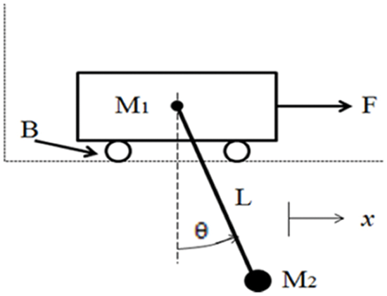
Figure 1: Wheeled inverted pendulum system equations
By referring several literature [16,17], dynamics of the wheeled type inverted pendulum are shown in the form of following two equation,
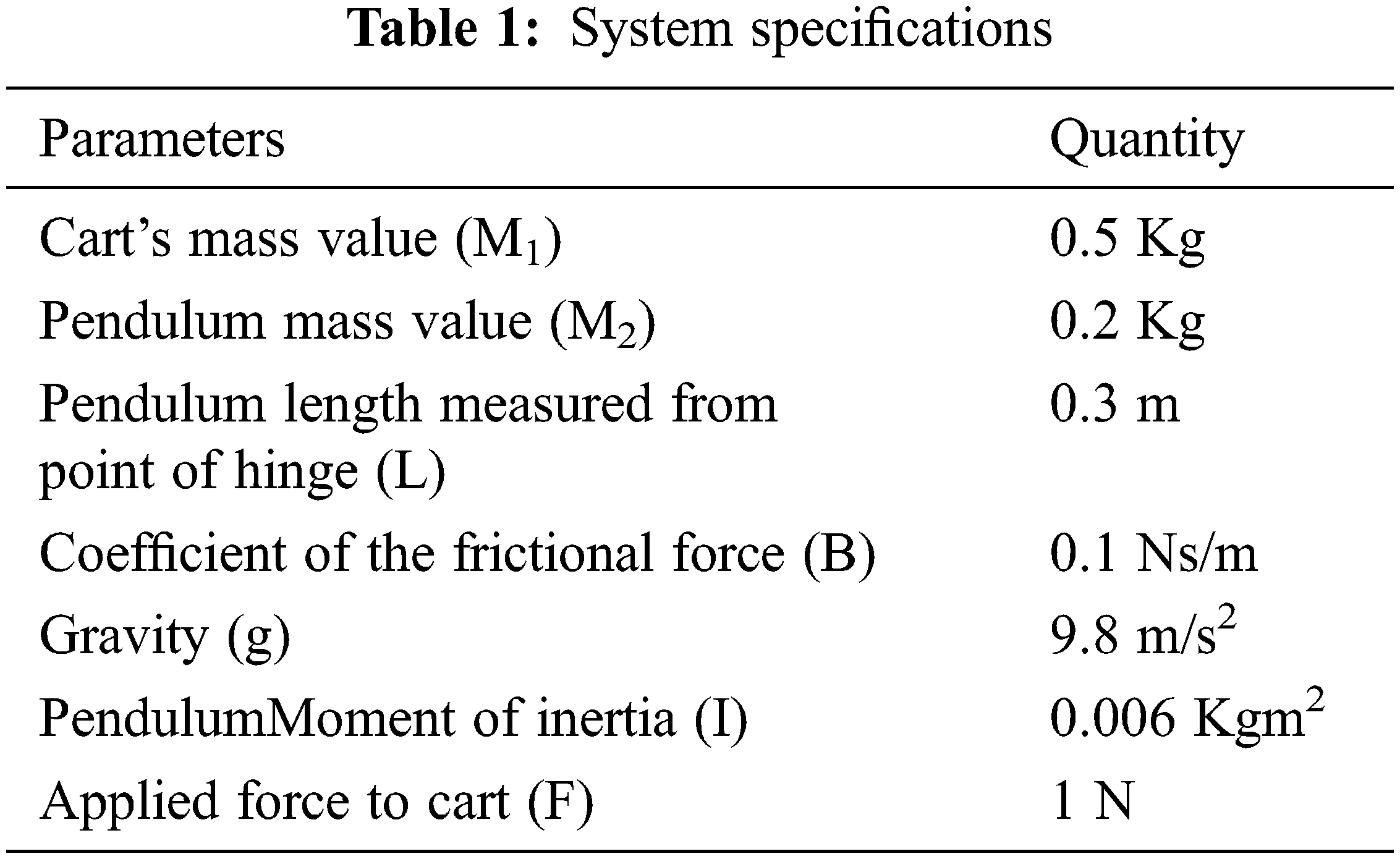
The system specification of a wheeled inverted pendulum is indicated in Tab. 1.
3 Mathematical Modeling of Inertial Sensors and Proximity Sensors
Gyroscope is a disc or spinning circle where at any direction the axis is in free rotation. During rotating or bending or twisting, direction of this pole is explicitly predicted on the law of conservation of angular momentum.
The transfer function of IMU device sensor is
The transfer function for a low Pass Filter type is
where,
ωn is the undamped angular frequency of the corresponding oscillator.
ζ is the damping ratio that indicates the behavior of the system. Similarly, ζ = 1 responds to critically damped, huge system values give over damped and smaller values being under damped. For ζ = 0, the system behaves as undamped and ω indicates the angular frequency.
A proximity sensor also transmits an electromagnetic radiation pulse or the electromagnetic field that scans for variations in the feedback signal or in a range signal, which is shown in Fig. 2.
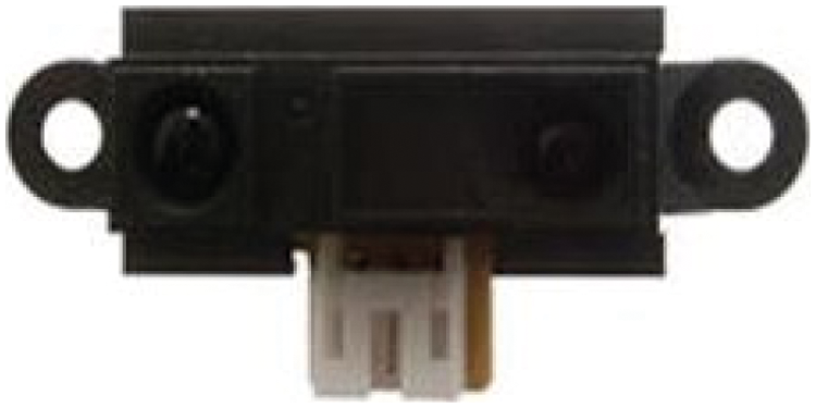
Figure 2: Proximity sensor
The info driven simulation process is carried out to avail transition mechanism for the dynamics by taking the toolbox for device recognition. Two types of transfer functions are added in this case for slow dynamics and for fast dynamics. The transition functions are controlled and driven by a pulse variant generator device. The slow dynamics increases above 30mv at the pulse based analysis with the static gain 0.03. The Transfer function of sensor (proximity) is
Two constant values of inertial sensors are sent to the logic after that limited range white noise signal is added. These are applied as inputs to the gain block; it multiplies the input signal by some specified number and produces the result. The output result received from the gain section is noise type signal. To eradicate this noise type signal we choose Fast Fourier Transform (FFT) algorithm. In this FFT algorithm, low pass filters are incorporated to avoid the high frequency signal and produce a zero noiseless signal to the section of simgyro. To completely vanish the noise type signal, FFT algorithm is functionally used in the section of Simulink. Simulation model of an inertia sensor is shown in Fig. 3.
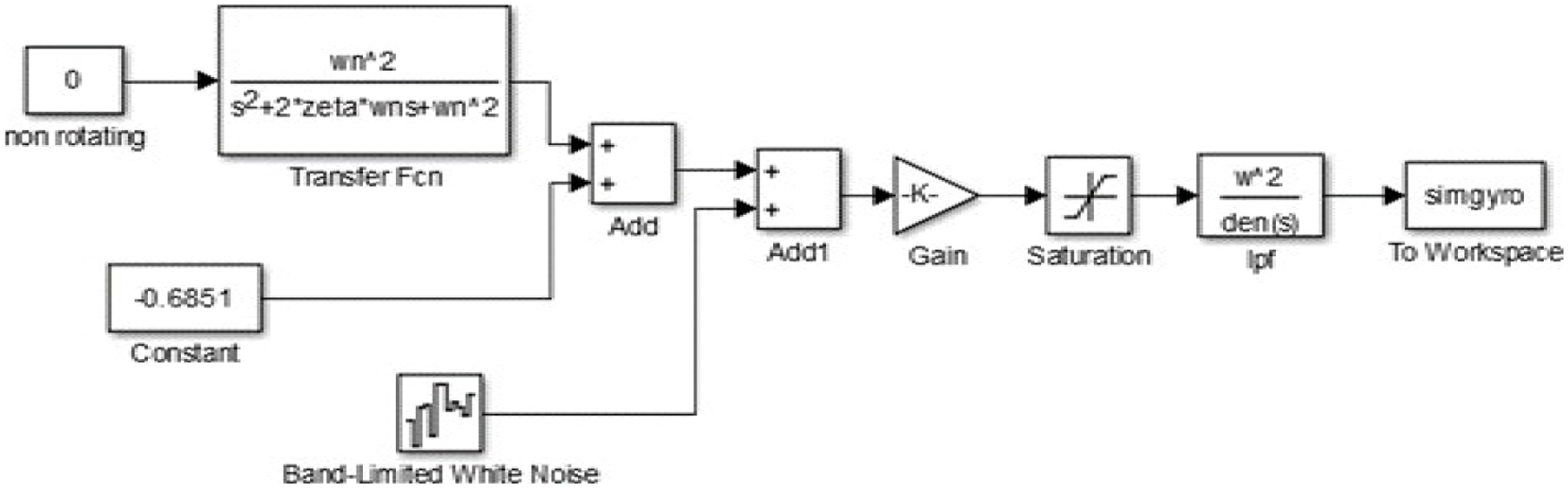
Figure 3: Simulink modelling of inertial sensor
simgyronobias = simgyro − mean (simgyro);
[f,amp] = myfft (simgyronobias*0.00875, 1/95);
Figs. 4 and 5 shows the noisy and noiseless output of the inertial sensor. The Infrared Proximity Sensor device is the major block of the system. A value of constant type is sent to the structure. After that limited band white noise signal and two number of dynamic transfer operations are put together. Two types of transfer functions are added in this case for slow dynamics and for faster dynamics. These will produce a noisy resultant signal. Figs. 6 and 7 shows the noisy and noiseless output of proximity Sensor. The Inputs applied to this logic system is
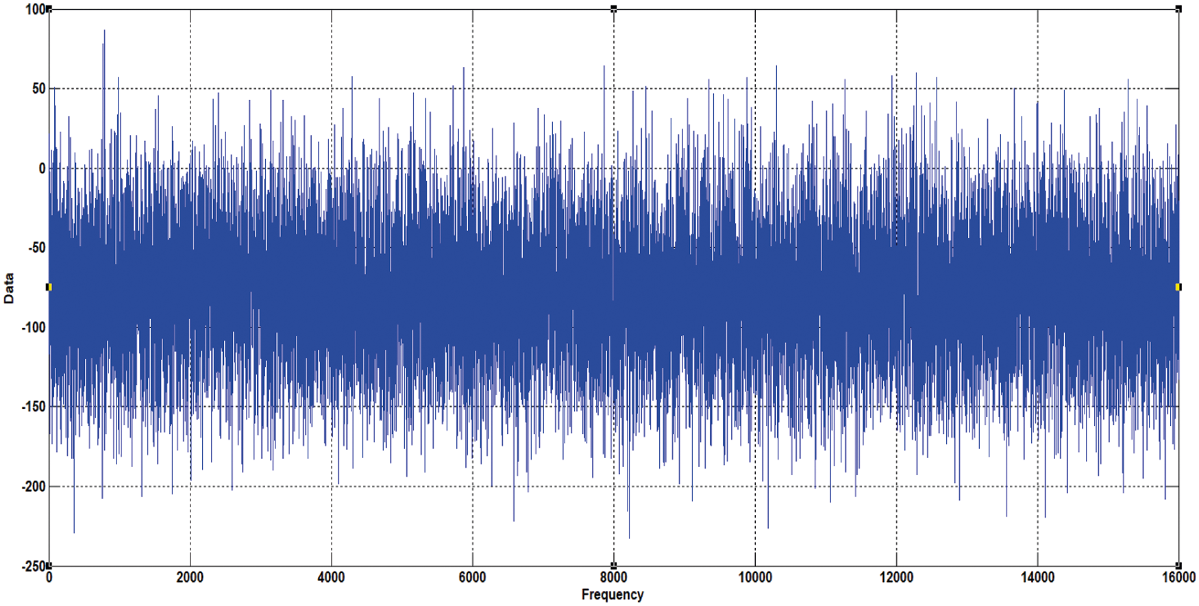
Figure 4: Noisy result from inertial sensor
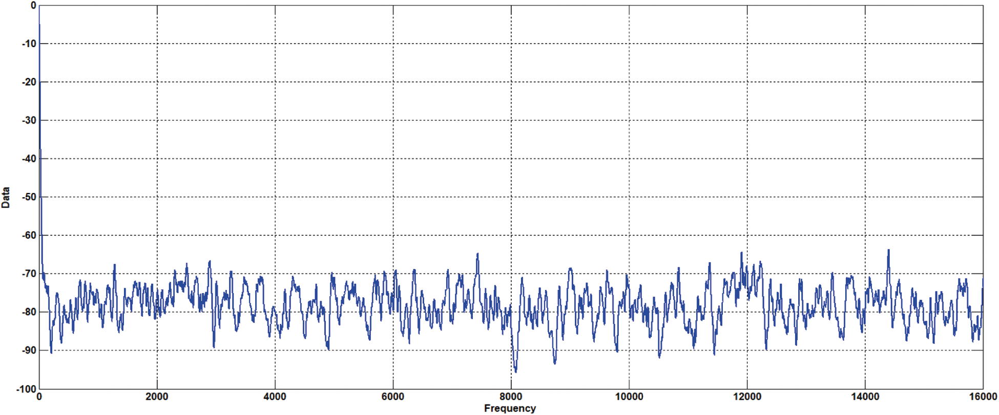
Figure 5: Noiseless result from inertial sensor
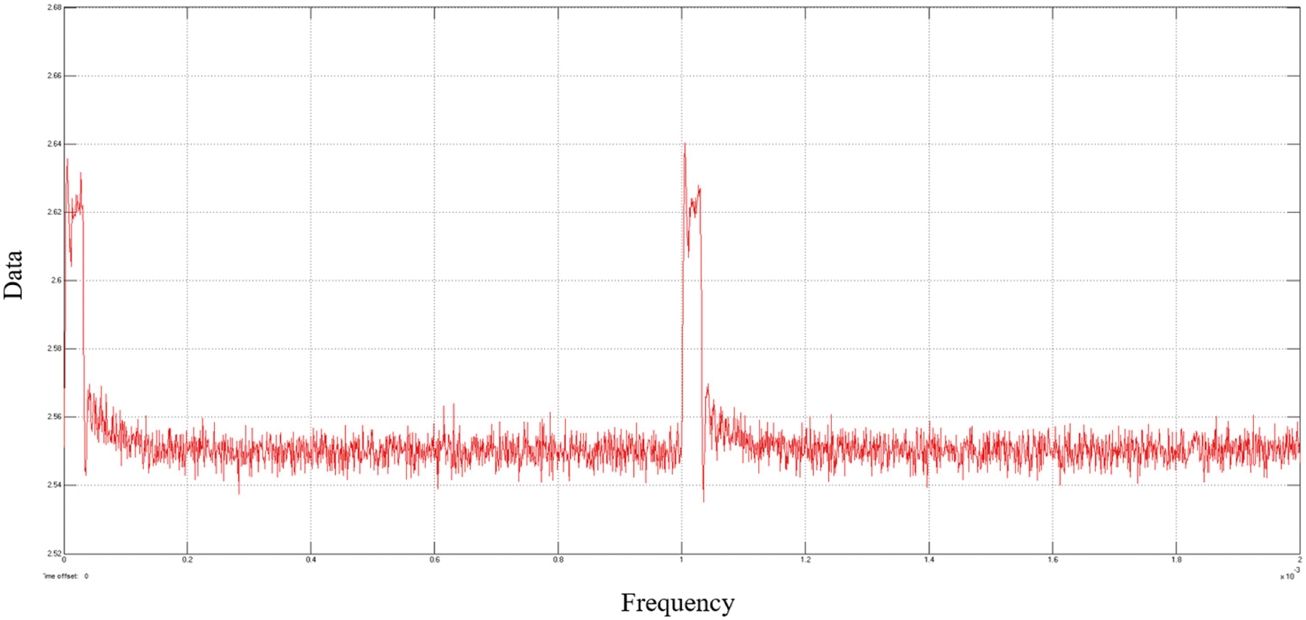
Figure 6: Noisy output of proximity sensor
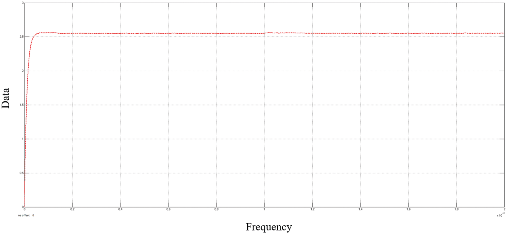
Figure 7: Noiseless output of proximity sensor
Table data values = [0 2.3 2.75 2.55 2 1.55 1.25 1.05 0.9 0.80.725 0.65 0.6 0.55 0.5 0.495 0.49];
Break points levels = [0 10 15 20 30 40 50 60 70 80 90 100 110 120 130 140 150]/100;
The robot-mounted inertial sensor and proximity sensor provides the microcontroller device with details about the area. The system uses ANFIS to fuse input signals from the individual sensors. Figs. 8 and 9 indicate the diagram of data fusion logic system. The robotic type model is put in the experiment in front face of the wall and it is allowed to March backwards in order to catch the difference occurred in between the robotic model and obstacle. Every time stamp also reported the actual distance. The sensors correlate with hardware to give the same quantity of samples of data over a given time period. In other terms, to view the fusion results, both the spatial alignment and the temporal alignment are outputted. The algorithm applied to data fusion is as follows:
Step 1: Accumulate info from individual sensor device.
Step 2: Evaluate the root mean square error (Es) allied along with sensor datum from each sensor device.
Step 3: Generate a fuzzy engine along with encoded input/output parameters by means of ANFIS. The Input to the fuzzy engine is datum from transducers and the final output result of the fuzzy system engine is original distance value, calculated manually.
Step 4: Repeatedly train the fuzzy engine up to no enhancement need required in the precision.
Step 5: check whether root mean square error (E) result of fusion algorithm is lesser than smallest value Es across each sensor?
Step 6: Check, if not satisfied, repeat step 4.
Step 7: If condition satisfied, halt training and set up the fuzzy system engine with hardware.
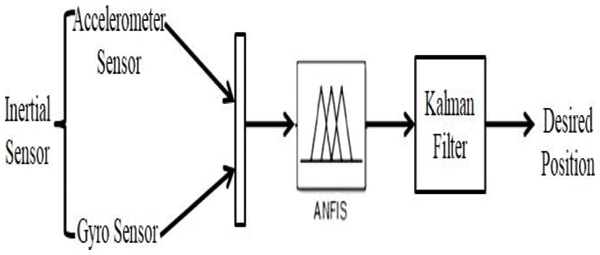
Figure 8: Sensor fusion between the heterogeneous sensors
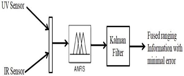
Figure 9: Sensor fusion between the homogeneous sensors
ANFIS is an artificial neural type logic rely on Takagi-Sugeno fuzzy inference scheme, which adds the features of both Fuzzy Logic Controller (FLC) and Neural networks. Also, it is sugeno based fuzzy inference logic in which the variables linked with specific membership functions are evaluated using either a reverse propagation gradient descent algorithm alone or in addition of least square technique. This type has been widely used in random data sequences with huge irregular dynamics. ANFIS controllers are designed to fuse the sensors. The ANFIS parameters are listed in Tab. 2 to perform the simulation. The error analysis is shown in Tab. 3 based on the RMSE and MAPE. It has been found that RMSE for resultant output value of fusion based algorithm is much poor. The Figs. 10–12 & 16 represents the ANFIS loading data, trained data, ANFIS structure and controlled response related to Pendulum angle respectively. The Figs. 13–15 & 17 represents the ANFIS loading data, trained data, ANFIS structure and controlled response related to Cart‘s position respectively.
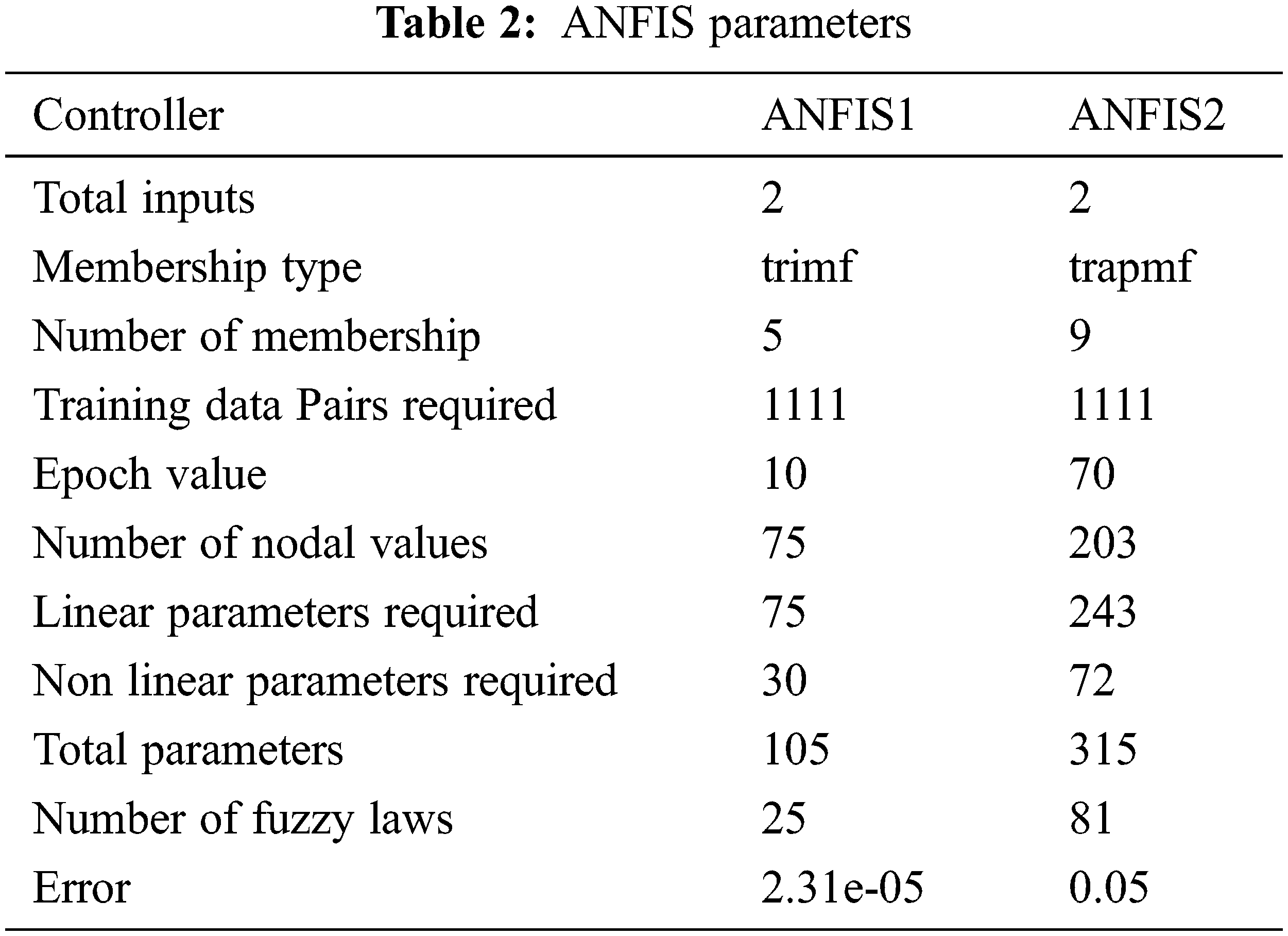
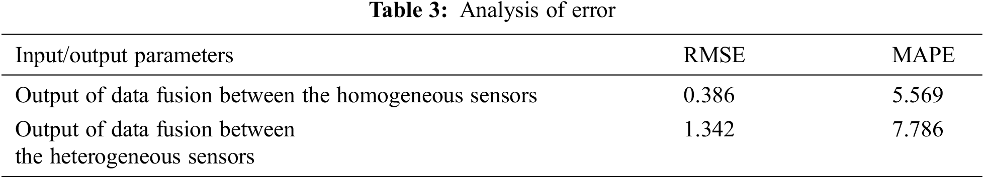
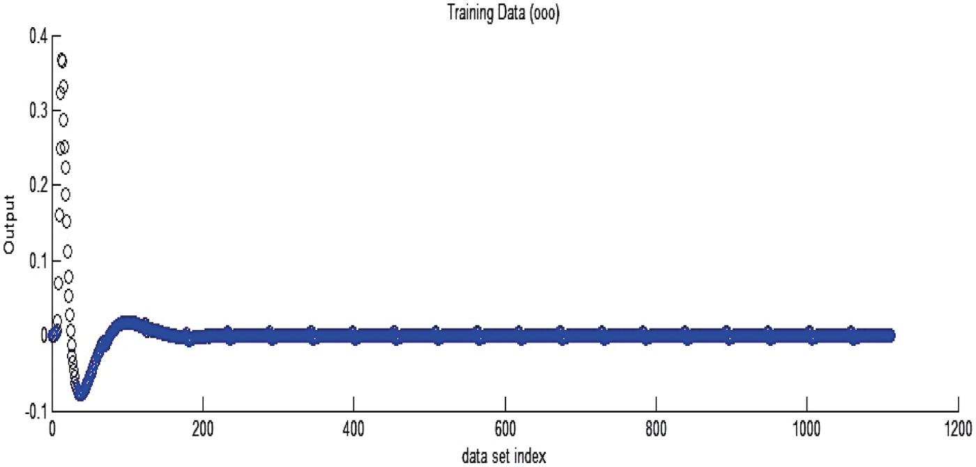
Figure 10: ANFIS-loading data of homogeneous sensors
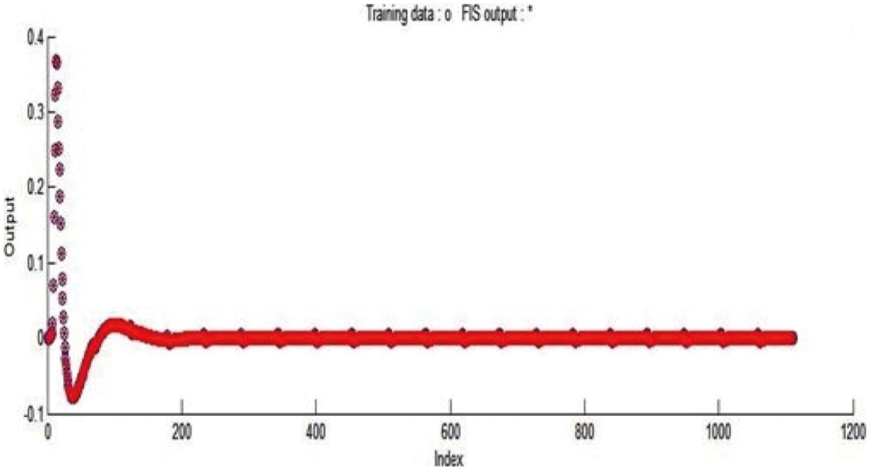
Figure 11: ANFIS-trained data of homogeneous sensors
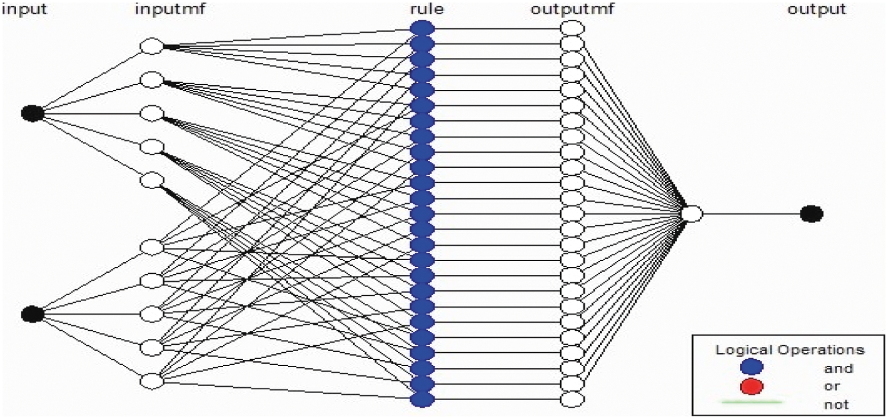
Figure 12: ANFIS structure of homogeneous sensors
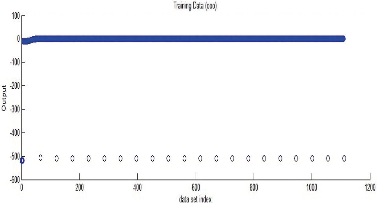
Figure 13: ANFIS-loading data of heterogeneous sensor
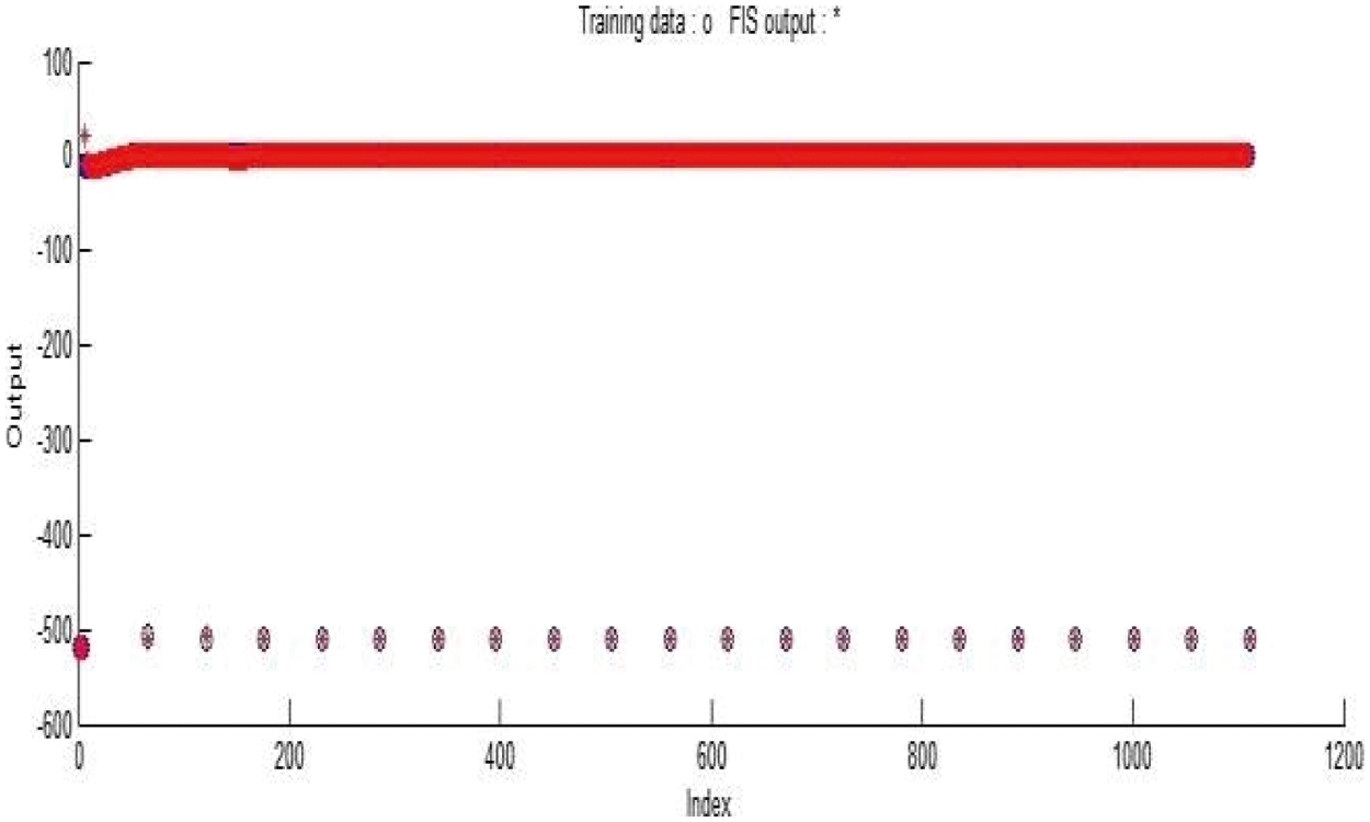
Figure 14: ANFIS-loading data of heterogeneous sensors
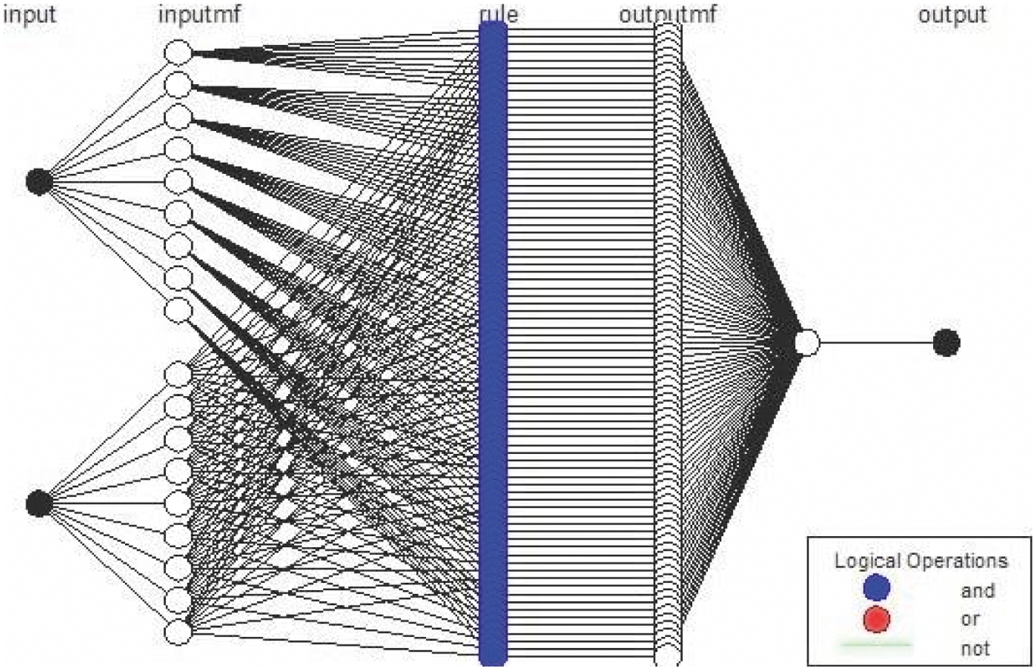
Figure 15: ANFIS structure of heterogeneous sensors
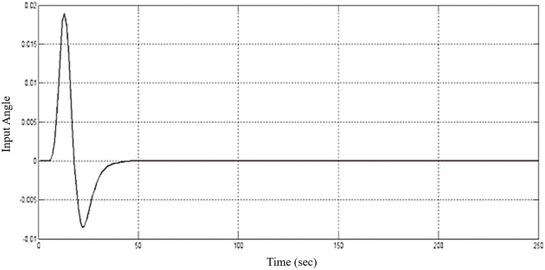
Figure 16: ANFIS controlled position response
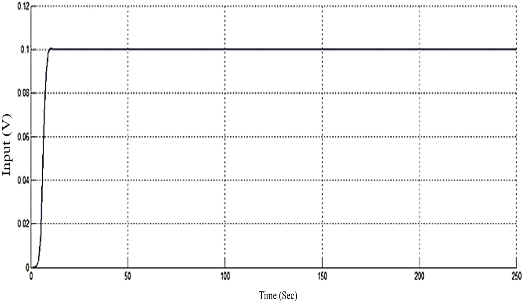
Figure 17: ANFIS controlled ranging response
The neuro-fuzzy fusion algorithm could overcome the shortcomings of individual sensors on interpretation of the world. The output result is checked and verified by application of error analysis technique (RMSE, MAPE) carried on the sensor info and by using the fusion based algorithm. This propounded technique of ANFIS based fusion algorithm has improved RMSE for both homogeneous sensors and heterogeneous type sensors. Robotic systems may execute several control strategies in various proximity levels based on the performance of the data fusing algorithm. In future, simulation work will be implemented as sensor fabrication based on 3D printed technology.
Funding Statement: The authors received no specific funding for this study.
Conflicts of Interest: The authors declare that they have no conflicts of interest to report regarding the present study.
1. S. Kim and S. Kwon, “Nonlinear optimal control design for under actuated two-wheeled inverted pendulum mobile platform,” IEEE/ASME Transactions on Mechatronics, vol. 22, no. 6, pp. 2803–2808, 2017. [Google Scholar]
2. M. S. Mahmoud and M. T. Nasir, “Robust control design of wheeled inverted pendulum assistant robot,” IEEE/CAA Journal of Automatica Sinica, vol. 4, no. 4, pp. 628–638, 2017. [Google Scholar]
3. K. Umamaheswari, G. Prabhakar, K. Viji and P. Thanapal, “Anfis PD plus I control onsimscape model of nonlinear physical system,” Control Engineering and Applied Informatics, vol. 23, no. 1, pp. 50–59, 2021. [Google Scholar]
4. A. Girard, J. L. Bigué, B. M. O’Brien, T. A. Gisby, I. A. Anderson et al., “Soft two-degree-of-freedom dielectric elastomer position sensor exhibiting linear behavior,” IEEE/ASME Transactions on Mechatronics, vol. 20, no. 1, pp. 105–114, 2015. [Google Scholar]
5. J. Chossat, Y. Park, R. J. Wood and V. Duchaine, “A soft strain sensor based on ionic and metal liquids,” IEEE Sensors Journal, vol. 13, no. 9, pp. 3405–3414, 2013. [Google Scholar]
6. P. Wawrzynskia, J. Możarynb and J. Klimaszewski, “Robust estimation of walking robots velocity and tilt using proprioceptive sensors data fusion,” Robotics and Autonomous Systems, vol. 66, no. 4, pp. 44–54, 2015. [Google Scholar]
7. B. Duraisamy, M. A. Gabb, A. V. Nair, T. Schwarz and T. Yuan, “Track level fusion of extended objects from hetero generous sensors,” in 19th Int. Conf. on Information Fusion (FUSION), Heidelberg, pp. 876–885, 2016. [Google Scholar]
8. J. Kim, D. S. Han and B. Senouci, “Radar and vision sensor fusion for object detection in autonomous vehicle surroundings,” in 10th Int. Conf. on Ubiquitous and Future Networks (ICUFN), Prague, pp. 76–78, 2018. [Google Scholar]
9. H. Aliakbarpour, J. F. Ferreira, V. B. S. Prasath, K. Palaniappan, G. Seetharama et al., “A Probabilistic fusion framework for 3-D reconstruction using heterogeneous sensors,” IEEE Sensors Journal, vol. 17, no. 9, pp. 2640–2641, 2017. [Google Scholar]
10. R. Rasoulzadeh and A. M. Shahri, “Implementation of A low-cost multi-IMU hardware by using a homogenous multi sensorfusion,” in 4th Int. Conf. on Control, Instrumentation, and Automation (ICCIA), Qazvin, pp. 451–456, 2016. [Google Scholar]
11. W. Liu, Y. Lu and S. F. Jeffrey, “CFAR data fusion of multistatic radar system under homogeneous and nonhomogeneous backgrounds,” in RADAR, Edinburgh, UK, pp. 248–252, 2002. [Google Scholar]
12. S. Muthu Viswadharani, G. Prabhakar and S. Selvaperumal, “Analysis on soft sensor design in Simulink,” in Int.Conf. on Advanced Communication Control and Computing Technologies (ICACCCT), Ramanathapuram, pp. 372–375, 2016. [Google Scholar]
13. P. Gunasekaran, S. Sundaramoorthy and N. P. Pulikesi, “Fault data injection attack on car-following model and mitigation based on interval type-2 fuzzy logic controller,” IET Cyber-Physical Systems: Theory & Applications, vol. 4, no. 2, pp. 128–138, 2019. [Google Scholar]
14. S. M. Radaideh and M. T. Hayajneh, “A new fuzzy gain scheduling scheme for the PID controllers,” Intelligent Automation & Soft Computing, vol. 9, no. 4, pp. 269–277, 2003. [Google Scholar]
15. G. Prabhakar, S. Selvaperumal and P. Nedumal Pugazhenthi, “Fuzzy PD plus I control-based adaptive cruise control system in simulation and real-time environment,” IETE Journal of Research, vol. 65, no. 1, pp. 69–79, 2018. [Google Scholar]
16. Y. Chen and C. Chang, “An intelligent ANFIS controller design for a mobile robot,” in IEEE Int. Conf. on Applied System Invention (ICASI), China, pp. 445–448, 2018. [Google Scholar]
17. C. Chen, R. Jafari and N. Kehtarnavaz, “A real-time human action recognition system using depth and inertial sensor fusion,” IEEE Sensors Journal, vol. 16, no. 3, pp. 773–781, 2016. [Google Scholar]
18. K. Liu, C. Chen, R. Jafari and N. Kehtarnavaz, “Fusion of inertial and depth sensor data for robust hand gesture recognition,” IEEE Sensors Journal, vol. 14, no. 6, pp. 1898–1903, 2014. [Google Scholar]
19. H. Chang and J. Chang, “Sensor glove based on novel inertial sensor fusion control algorithm for 3-D real- time hand gestures measurements,” IEEE Transactions on Industrial Electronics, vol. 67, no. 1, pp. 658–666, 2020. [Google Scholar]
20. D. Felix, D. Görges and A. Wienss, “Impacts of inertial sensor errors on both data fusion and attitude-based bicycle rider assistance systems in order to derive sensor requirements,” in IEEE Int. Symp. on Inertial Sensors and Systems (INERTIAL), Naples, FL, USA, pp. 1–4, 2019. [Google Scholar]
21. H. Zhao and Z. Wang, “Motion measurement using inertial sensors, ultrasonic sensors, and magnetometers with extended kalman filter for data fusion,” IEEE Sensors Journal, vol. 12, no. 5, pp. 943–953, 2012. [Google Scholar]
22. V. Sangwan, R. Kumar and A. K. Rathore, “State-of-charge estimation for li-ion battery using extended Kalman filter (EKF) and central difference Kalman filter (CDKF),” in IEEE Industry Applications Society Annual Meeting, Cincinnati, OH, pp. 1–6, 2017. [Google Scholar]
23. M. Partovibakhsh and G. Liu, “An adaptive unscented kalman filtering approach for online estimation of model parameters and state-of-charge of lithium-ion batteries for autonomous mobile robots,” IEEE Transactions on Control Systems Technology, vol. 23, no. 1, pp. 357–363, 2015. [Google Scholar]
 | This work is licensed under a Creative Commons Attribution 4.0 International License, which permits unrestricted use, distribution, and reproduction in any medium, provided the original work is properly cited. |