DOI:10.32604/iasc.2022.023863
| Intelligent Automation & Soft Computing DOI:10.32604/iasc.2022.023863 | |
| Article |
Novel L2CL-LCL Topology for Wireless Power Transmission PMSM Powered Electrical Vehicle
1Department of EEE, Jyothi Engineering College, Thrissur, 679531, India
2Department of ECE, Jyothi Engineering College, Thrissur, 679531, India
*Corresponding Author: Jenson Jose. Email: jensonjosepapers678@gmail.com
Received: 24 September 2021; Accepted: 15 November 2021
Abstract: The Wireless Power Transmission (WPT) technology is a significant source of operation in the field of power transmission with tremendous potential in a wide range of applications. This paper proposes a novel strategy for L2CL-LCL topology, which comprises two capacitors and one inductor in the essential and one capacitor and one inductor in the auxiliary. Using MATLAB simulation, this paper compares the traditional DSLCL system and the proposed L2CL-LCL. The various parameters of this system are simulated. In the current system, input and output power are set to 200.1 and 182.4 W. The common framework’s start to finish efficiency can be estimated as 90.10%. The input and output power for the proposed framework is 224.2 and 211.05 W. The proposed framework has a general efficiency of 95.2%, which is greater than the traditional system. The output of this topology is taken care of to an electric vehicle powered by Permanent Magnet Synchronous Motor. The efficiency of the electric vehicle gets improved to about 65.5%, which is better than the average efficiency of an electric vehicle. The various parameters of the electric vehicle are simulated. The experimental analysis also proves that the results provided closely resemble theoretical research, demonstrating the superiority of the proposed system.
Keywords: Power transmission; inductor; full-bridge inverter; electrical vehicle system; battery voltage
Electrical energy assumes a crucial function for making human existence more helpful and agreeable. In many previous years, the transmission of electrical energy was done through wired networks. Nonetheless, the rise of utilizations like cell phones, electrically-controlled vehicles, space satellites, and biomedical implantable gadgets has required the need for exploration in Wireless Power Transfer (WPT) [1]. A compensation configuration is critical for a WPT framework since it decides the resonance frequency while limiting the power supply’s volt-ampere rating, boosting coupling power transfer capacity, and accomplishing high efficiency [2–5].
Parallel-Parallel (PP), Parallel Series (PS), Series-Parallel (SP), and Series-Series (SS) are the four major compensation configurations [6]. PS and PP, which are parallel compensation topologies, are not suitable for a WPT. A voltage-source inverter lays a framework by generating large current spikes at switching transitions [7]. The adverse effects of powerless misalignment tolerance can be seen in SS and SP compensation topologies. As the coupling deteriorates, the input impedance decreases. When the coupling factor is set to zero, the input impedance is also set to zero. It is extremely harmful as the voltage source is short-circuited. As a result, SS and SP are not applicable, requiring a large separation between two coupling coils, such as dynamic electric vehicle (EVs) charging [8]. Commercializing wireless charging technology in electric vehicles is still a massive problem because of the need for high efficiency and power with a broad misalignment tolerance [9].
The Inductor-Capacitor-Inductor (LCL) was proposed to improve misalignment tolerance and avoid massive current spikes [10–14].
An upgraded multi-load solution for WPT that employs an LCC/S architecture to maintain load power steady. An architecture like this ensures that the power delivered to the loads is consistent. By incorporating the LCC topology into the primary side of the WPT system, the current flowing through the transmitting coil may be adjusted more easily. If the loads in the system fulfill specific limits, the system can function at maximum efficiency. It is crucial to undertake more study depending on the system’s power requirement [15].
A double-sided LCL variable compensation topology with MCR-WPT (magnetically coupled resonance wireless power transfer system) is utilized for Constant current (CC) and Constant Voltage (CV) charging mode for an electric vehicle. The mathematical model is established for the double-sided LCL topology using a two-port network. The characteristics of CC and CV output modes are studied, respectively. In any case, the disadvantage is that the change of the framework input voltage can likewise influence the analysis results [16]. Tab. 1 shows the recent advancements in the field of compensation topologies used in WPT system.
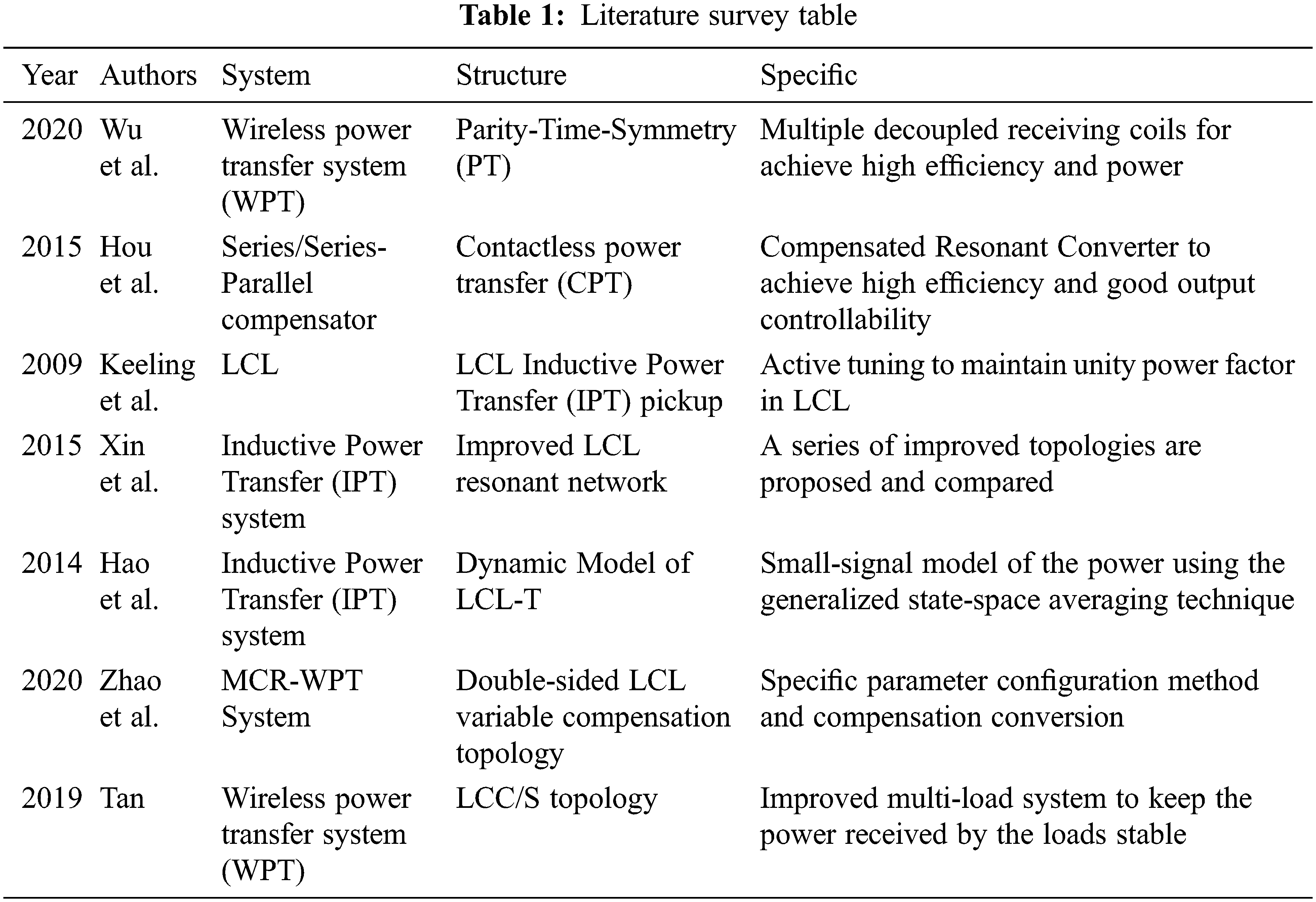
The double-sided LCC (DS LCC) compensation configuration has been proposed to take care of the issues identified with bidirectional power transfer [17]. DS LCC has its load-independent operation frequency preferences, zero-voltage switching (ZVS), and zero phase angle (ZPA). [18] As it may, DS LCC needs two additional compensation capacitors, prompting expanded framework cost, and decreased power density [19]. The operation principle and a boundary-tuning technique were presented. Inconveniences of DS LCL are the low degree of freedom and irregular input current. High effectiveness and low VA rating are its focal points.
Efficiency is one of the obliges which impacts the performance of the WPT framework. The efficiency of WPT was the principal centre while building up a few compensation topologies. Regular DS LCL has an efficiency of 87.3% [20]. A novel parameter tuning technique is actualized in DS LCL [21] with a general efficiency of 90.2%. Efficiency based plan improvement of the double-sided LCL wireless power transfer framework is proposed [22] and, the overall efficiency of the optimized is 92.67% [23].
In recent years EVs have gained acceptance as the most feasible choice for helping to protect the environment while also attaining significant energy savings in transportation. The intelligent charging system can determine the device’s location on its own, allowing for the efficient charging of the electric vehicle [24]. The key propulsion component in electric vehicles is the traction motor, which must have excellent power density and torque, a wide speed range, excellent performance, high dependability, and low distortion [25]. A hybrid control system improves the charging range and stability of electric vehicles under dynamic settings [26]. For EVs charging applications, L2CL-LCL Fig. 1a compensation is used in this work. A DC source, high-frequency inverter, L2CL-LCL compensating circuits, rectifier, and battery are all part of the EVs charging system shown in Fig. 1b. In high-performance drive systems like EVs, the Permanent Magnet Synchronous Motor (PMSM) has moved to the top among AC motors. PMSM has high torque-to-current rates, a high power-to-weight ratio, good performance, and ruggedness. Because of the advantages listed above, PMSMs are frequently employed in current variable speed AC drives, particularly in electric vehicle applications [27–30].
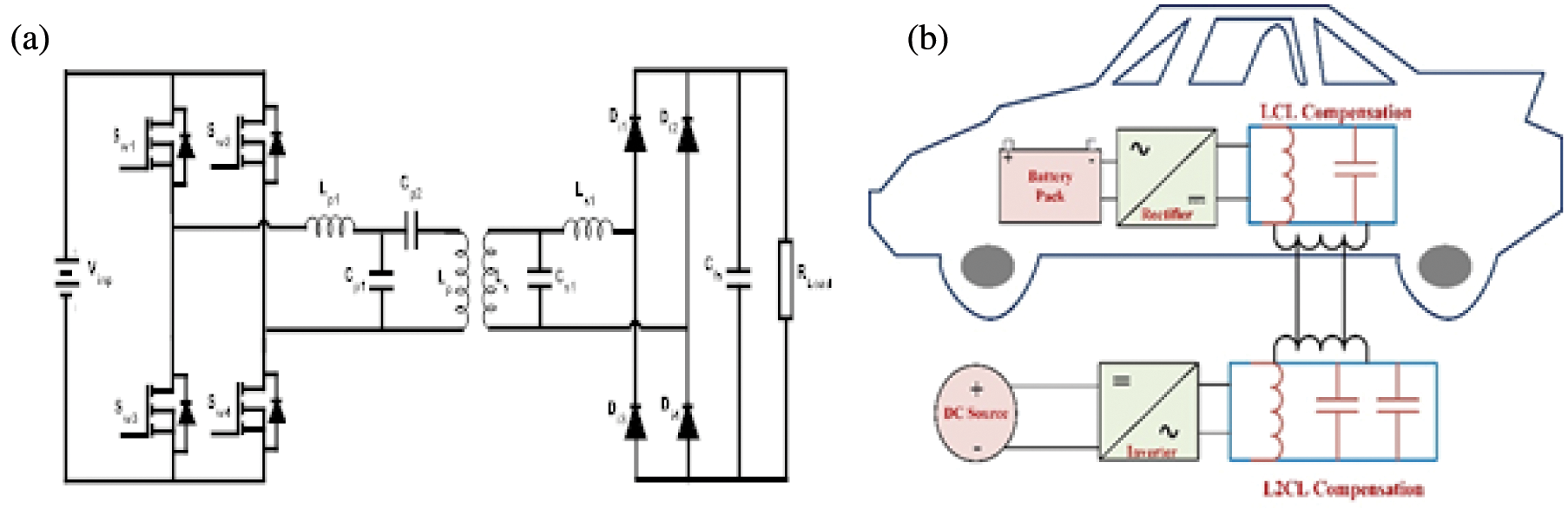
Figure 1: (a) Proposed circuit of the L2CL-LCL system, (b) wireless EV charging system
Due to its numerous advantages, PMSM is now often used in electric vehicles. The sinusoidal PWM with 180-degree variation controls the pulse to be sent to the switches in the inverter. The efficiency of an electric vehicle with a PMSM drive is in the range of 62%. The efficiency of the drive can be increased by up to 65.5% by using our topology.
2 Conventional Parameter Turning Method of Proposed L2CL-LCL System and Modeling of PMSM
Fig. 1 presents the circuit diagram of a proposed L2CL-LCL device. Sw1–Sw4 are four MOSFETs that make up a Full-Bridge Inverter, and Uinp is the initial input DC voltage. The switch pairs (Sw1, Sw4) and (Sw2, Sw3) conduct in turn. Lp1, Cp1 and Cp2, are the primary compensated inductors and capacitors. Ls1 and Cs1 are the secondary elements that correspond to each other. The analytical circuit of the proposed L2CL-LCL framework is as appeared in Fig. 2. For investigation purposes, the filter capacitor, load resistance and the diode rectifier circuit in Fig. 2 is replaced by its equivalent resistance RELoad.
RELoad can still be computed, as per reference [31].
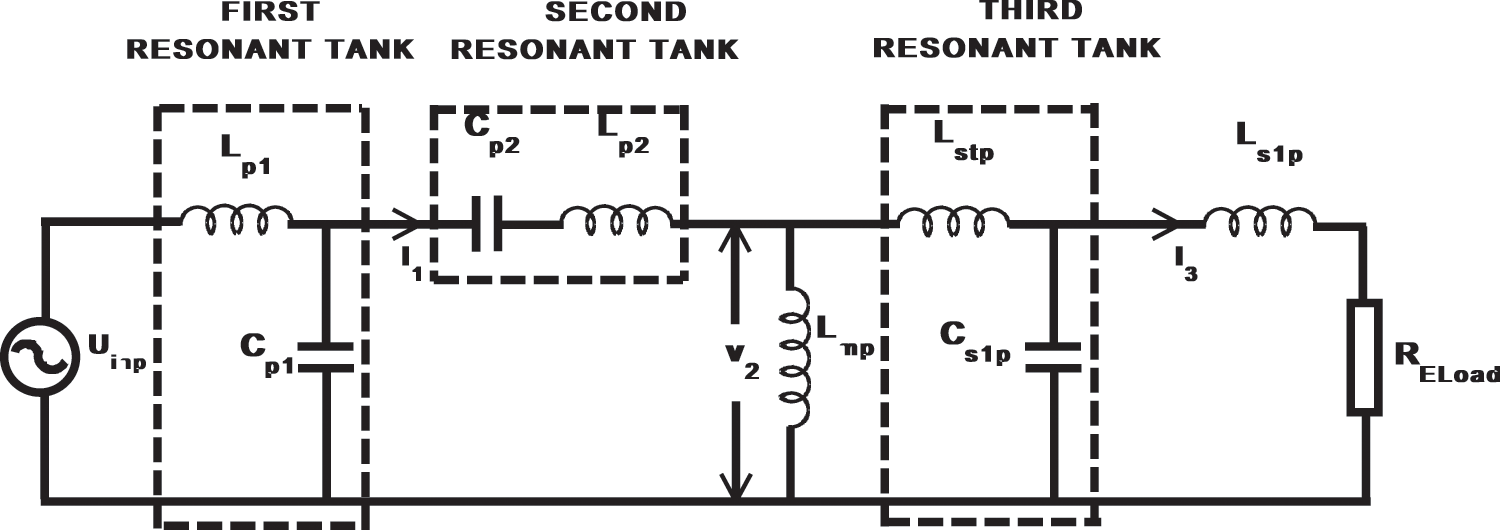
Figure 2: L2CL-LCL framework analytical circuit
The following basic equations are derived using the fundamental circuit concept [21].
Consider the dotted line in Fig. 2 which depicts three resonant circuits. A first resonant tank is formed when Lp1 and Cp1 resonate at the device operating frequency. Similarly, Cp2, Lp2 and Lstp, Cs1p make up the second and third resonant tanks.
These three resonant tanks resonate at the same system operating frequency ω0 [32,33].
Kirchhoff’s current and voltage law can be used to determine the output current of the first resonant tank,
Substituting Eq. (3) in Eq. (4)
Let I2 be the second resonant tank’s output current and V2 be the voltage across it.
Substituting the Eq. (5) in Eq. (6) and rearranging
Let I3 be the output current of the second resonant tank
Divide and Multiply Lp1 and Lp2 and substituting Eq. (3) into Eq. (8) I3 can be simplified as
The average Power consumed by RELoad is
RELoad consumes the Power specified in Eq. (10). Derived the current flowing through RELoad as per the energy conservation principle as
Substituting the value of PRELoad, after rearranging
Different parameters are rearranged as
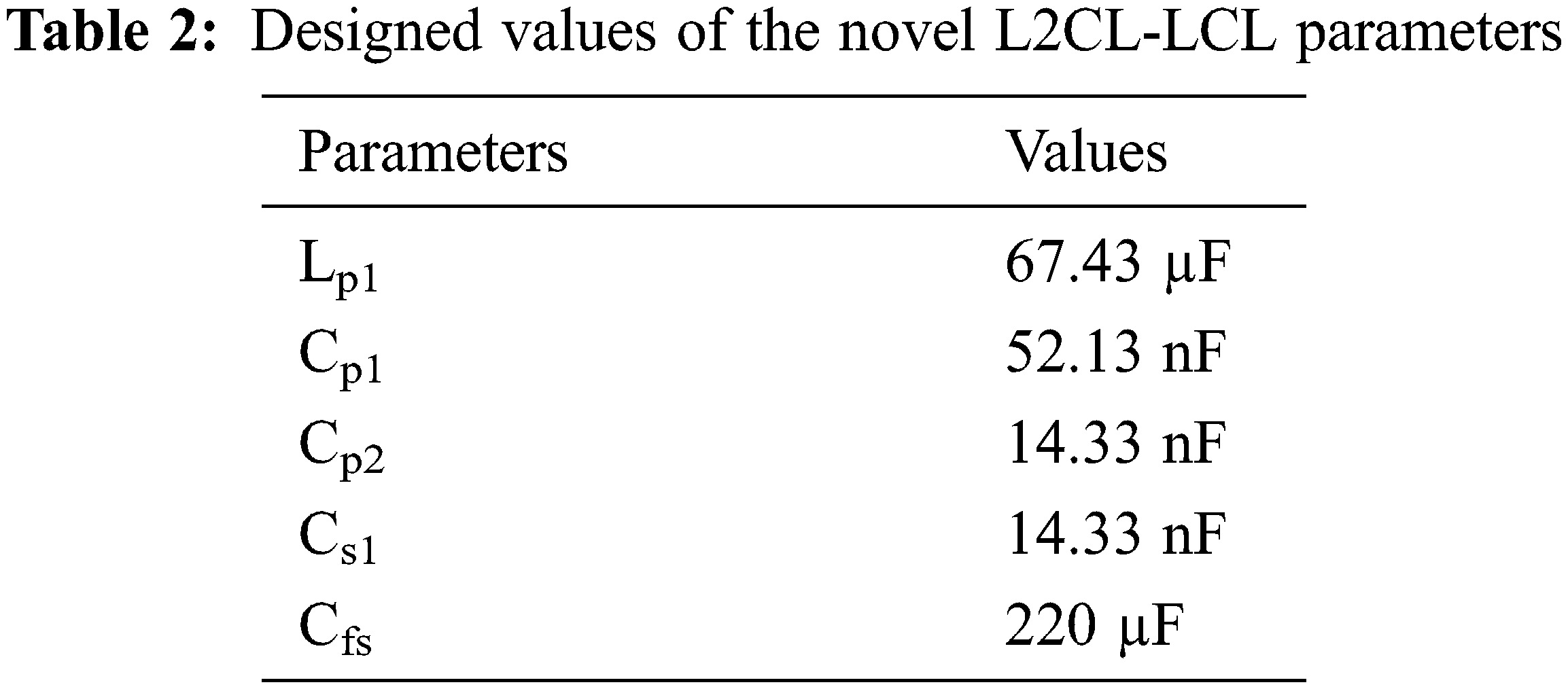
The Eqs. (12)–(15) are used to calculate the values of the passive elements. Tab. 2 lists the designed values of the novel L2CL-LCL parameters.
A permanent magnet’s back EMF generated by an energized coil is identical. Consequently, a PMSM has a mathematical model similar to the wound rotor Synchronous motor. The rotor frame was chosen because the instantaneous induced EMFs are determined by the orientation of the rotor magnets. The following assumptions are taken into consideration in the derivation.
• The induced EMF is sinusoidal; hence the stator windings are balanced, so saturation and parameter variations are ignored.
• Eddy current and hysteresis losses are close to zero.
• In the field, there are no current dynamics.
• On the rotor, there is no enclosure.
The motor’s electromagnetic torque is calculated as follows:
The voltage equations for three-phase stators are as follows
ω—Synchronous speed in rad/s
Park’s transformation is used to convert the stator voltages in the ‘abc’ axis Vabc to the d, q axes
Eqs. (23) and (24) give the stator current in a synchronously rotating reference frame
In terms of inductances and current, Eq. (25) gives the electromagnetic torque produced by the motor.
The relation between the load torque and electromagnetic torque is given by
P—Number of pole pairs; B—Damping coefficient; TL—Load torque; J—moment of inertia; ωm—Rotor speed.
Rotor mechanical speed ωm is provided by
Rotor electrical speed ωe is provided by
Rotor angle
The PMSM-powered electrical vehicle system is depicted in block diagram form in Fig. 3. An inverter receives the battery’s output. The PMSM is aided in driving the electric car by the AC supply provided by the inverter.
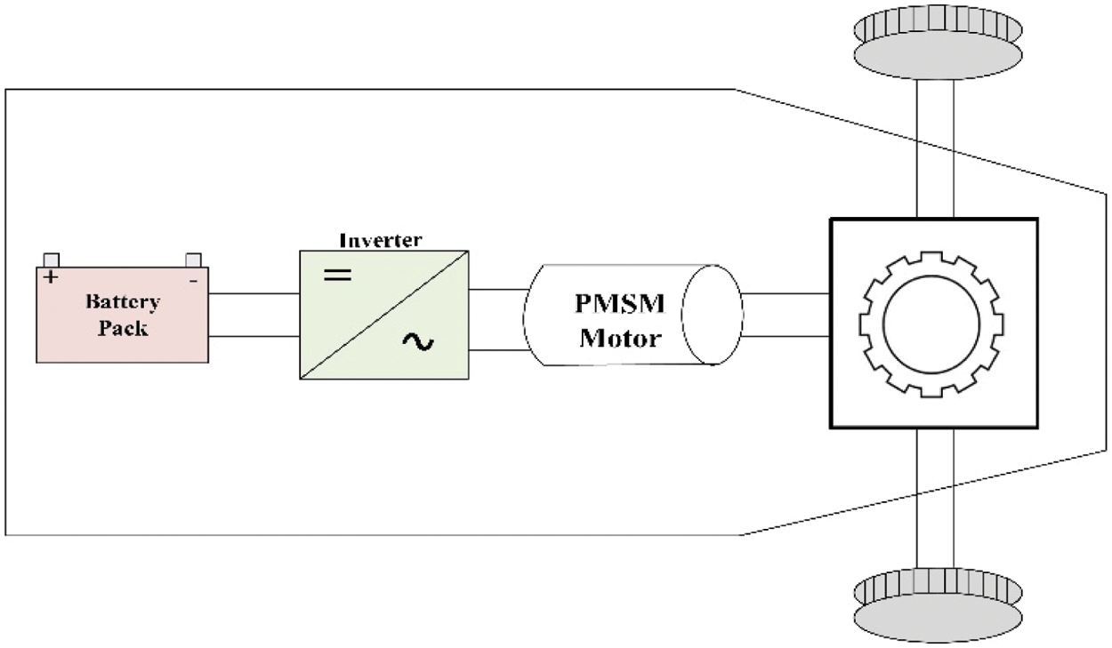
Figure 3: Block diagram of the PMSM powered electrical vehicle system
3 Design Example and Simulation Outcomes of Proposed System
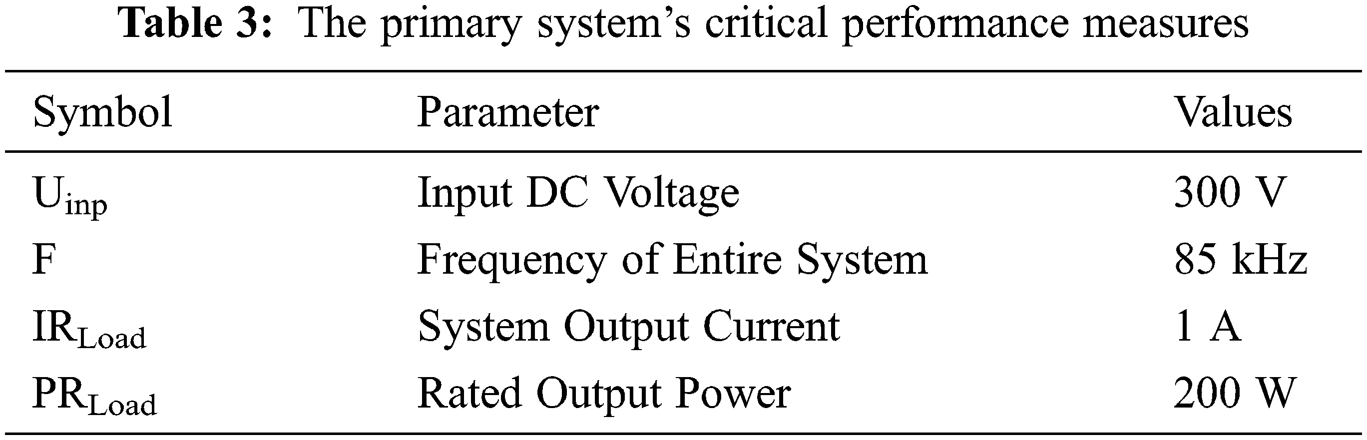
Tab. 3 shows the objective system’s simple presentation files. The rectifier diodes and inverter MOSFETs are the same as in the standard DS-LCL setup.
The output simulation considering various parameters and the tabulation for the proposed system is given. By varying various parameters, the output power vs. time is plotted in Fig. 4.
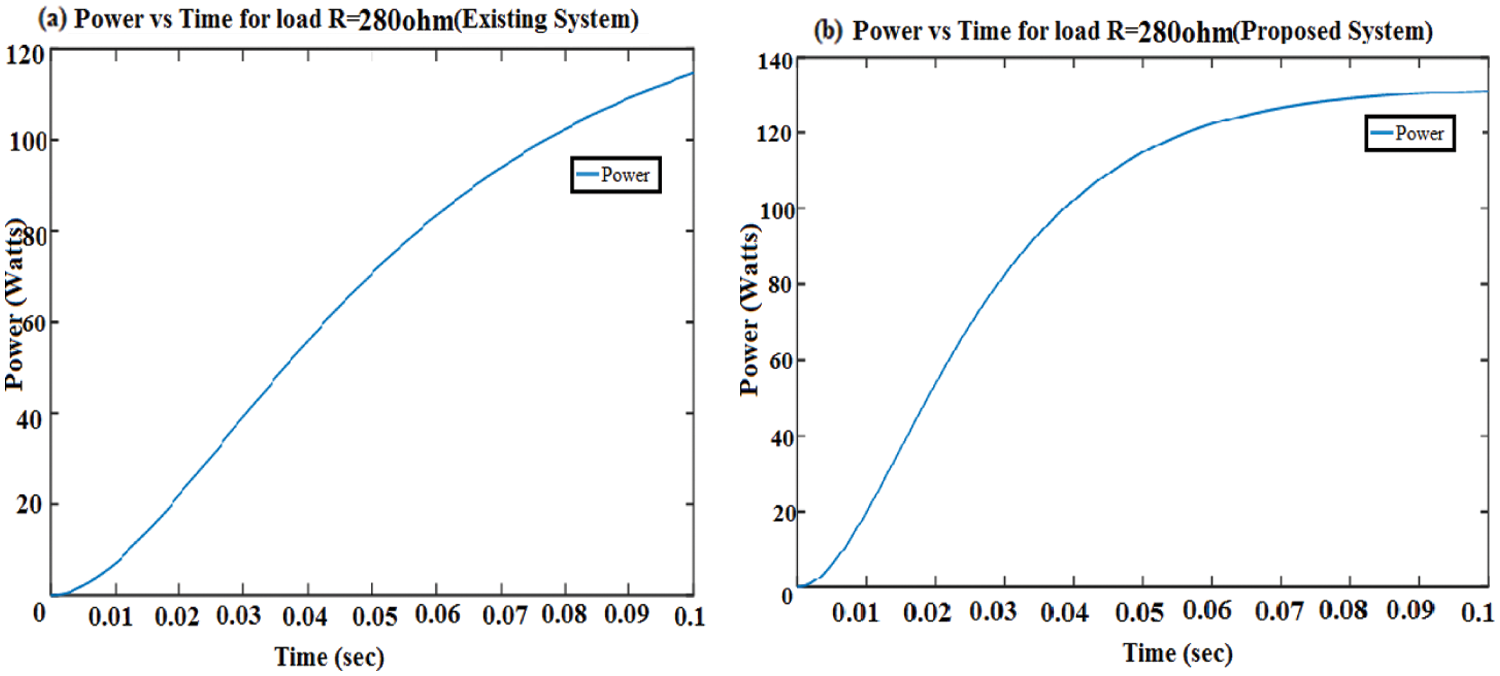
Figure 4: Output power vs. time waveform for load R = 280 ohm. (a) Traditional DS-LCL framework, (b) L2CL-LCL framework
When the resistance of the circuit gets increased compared to the original value, the current in the circuit gets reduced and voltage gets increased. The graph shows that the output power and efficiency have been increased by 21.9% (approximately 22%) and 3.2% respectively, compared to the traditional DS-LCL system.
When the resistance of the circuit gets reduced compared to the original value, the current and Power gets increased. From the graph, we can observe that the output power and efficiency have been increased by 14% and 0.4% respectively, compared to the traditional DS-LCL system. Tab. 4 shows the comparison result for various resistor values of the traditional and proposed system and the comparison values of the proposed and the traditional system for various capacitance values in Tab. 5.
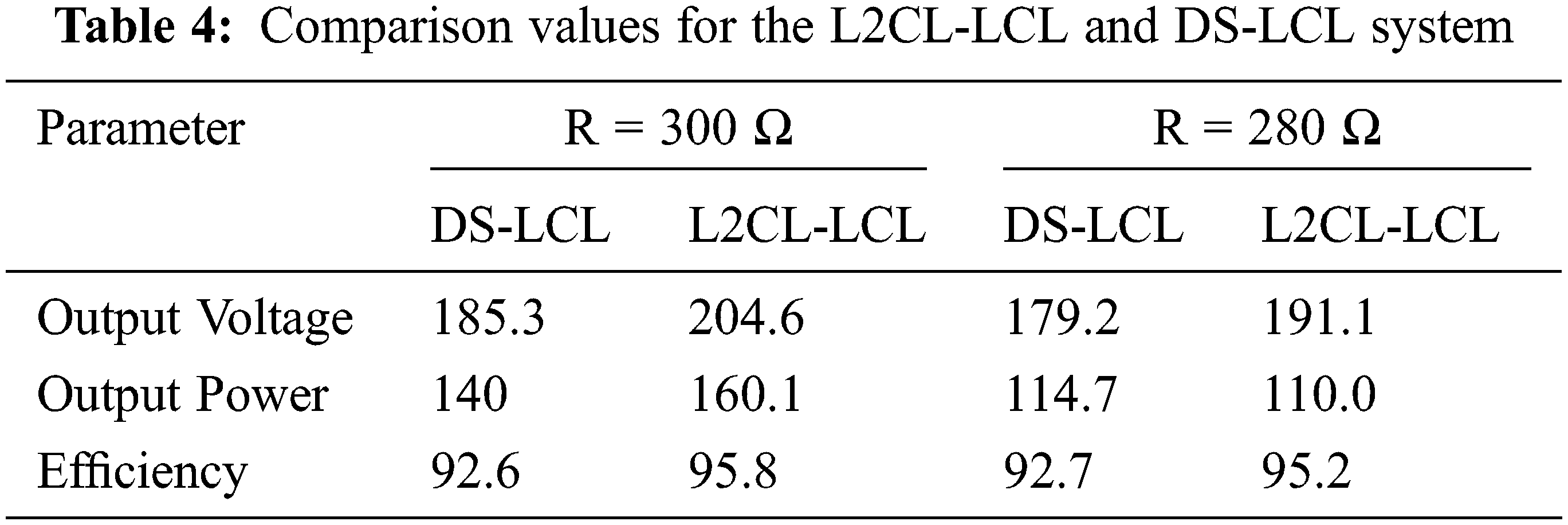
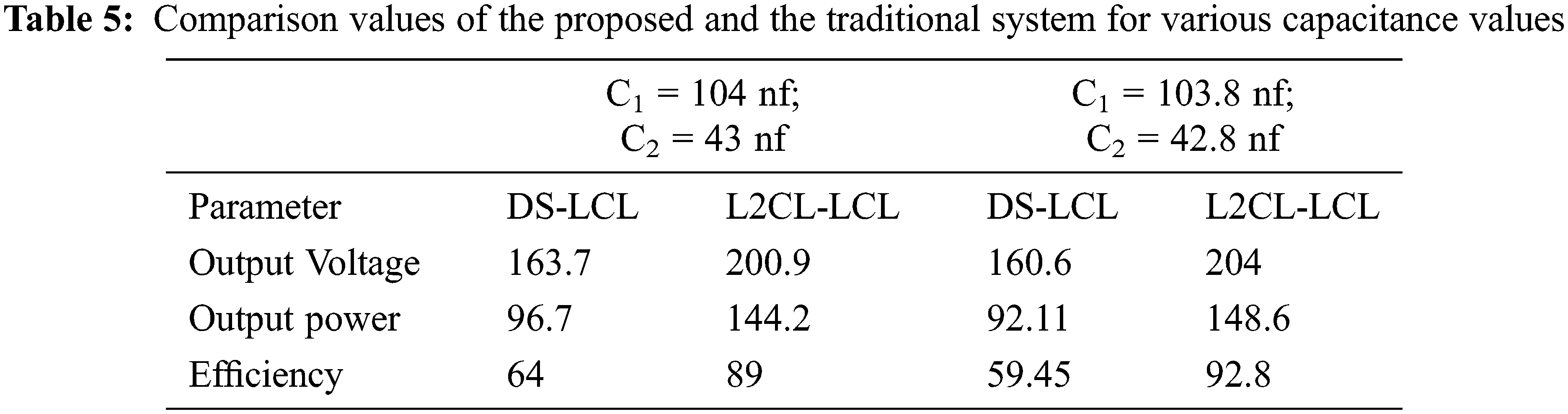
Fig. 5 compares two types of special compensations, DS-LCL and DS-LCC compensations, with the L2CL-LCL compensation. It is seen that the efficiency of the system is obtained as 95.03% which is better than the other two compensations, where DS-LCC has 93.1% and DS-LCL has 92.8%. It is seen that the efficiency of the system is obtained as 95.03% which is better than the other two compensations, where DS-LCC has 93.1% and DS-LCL has 92.8%.

Figure 5: Efficiency vs. frequency at different compensation topologies
Fig. 6 demonstrates that efficiency is proportional to the coefficient of coupling and frequency. The smaller the air spaces, the better efficiency. For maximum power transfer, it is critical to strike a balance between distance and efficiency while keeping the application in the account and the efficiencies of various rated power ratings with various misalignments are shown in Fig. 7. The efficiency of the aligned system decreases as the rated output power decreases, whereas the misaligned system’s efficiency is better than the aligned system’s at the same lower-rated Power.
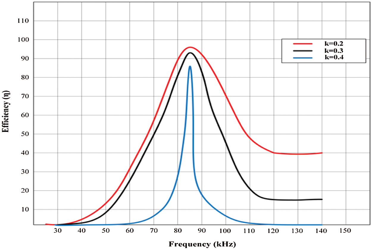
Figure 6: Efficiency vs. frequency at different coupling coefficients
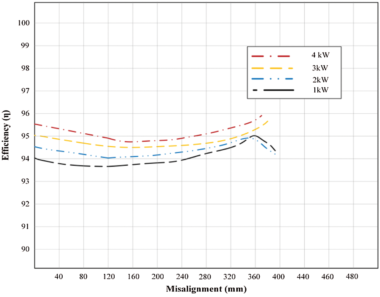
Figure 7: Efficiencies of various rated power ratings with various misalignments
Fig. 8 shows the simulation results for various coupling coefficients, input voltages, and output voltages under various battery voltage. For varying coupling coefficients and output voltages, the output power fluctuates linearly with the input voltages. Different coupling coefficients can be achieved by altering the spacing and misalignment between the receiver and transmitter coils.
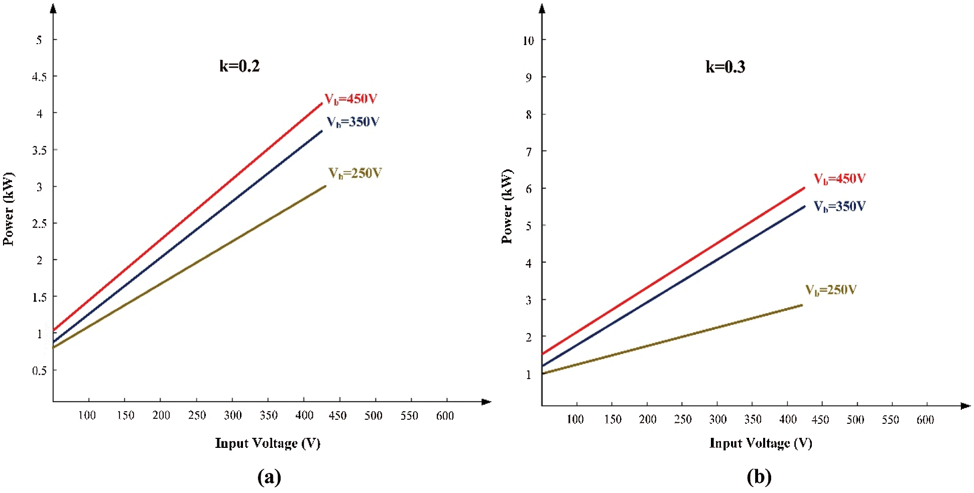
Figure 8: Simulation results for the L2CL-LCL system’s power levels (a) k = 0.2 (b) k = 0.3
Fig. 9 displays the hardware setup of the proposed system. It consists of Digital Storage Oscilloscope, Rheostat, Permanent Magnet Synchronous Motor, Load, Auto transformer and Field Programmable Gate Array (FPGA) controller. The output wave forms produced from the hardware setup is provided below. Fig. 10 shows the back EMF waveform of PMSM. Back EMF is a voltage developed by the motor’s rotation. As PMSM requires the AC supply, the back EMF generated in PMSM will be sinusoidal. Here the back EMF generated will be approximately equal to 20 V.
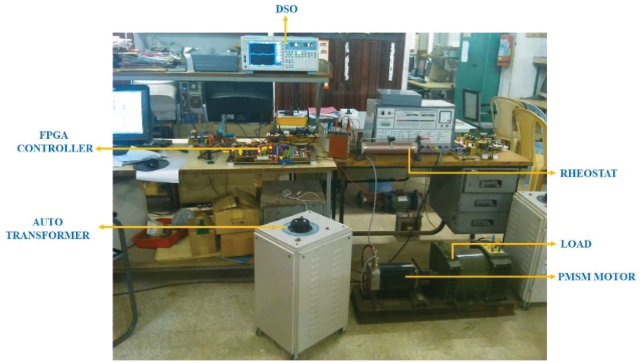
Figure 9: Hardware setup of the L2CL-LCL with PMSM
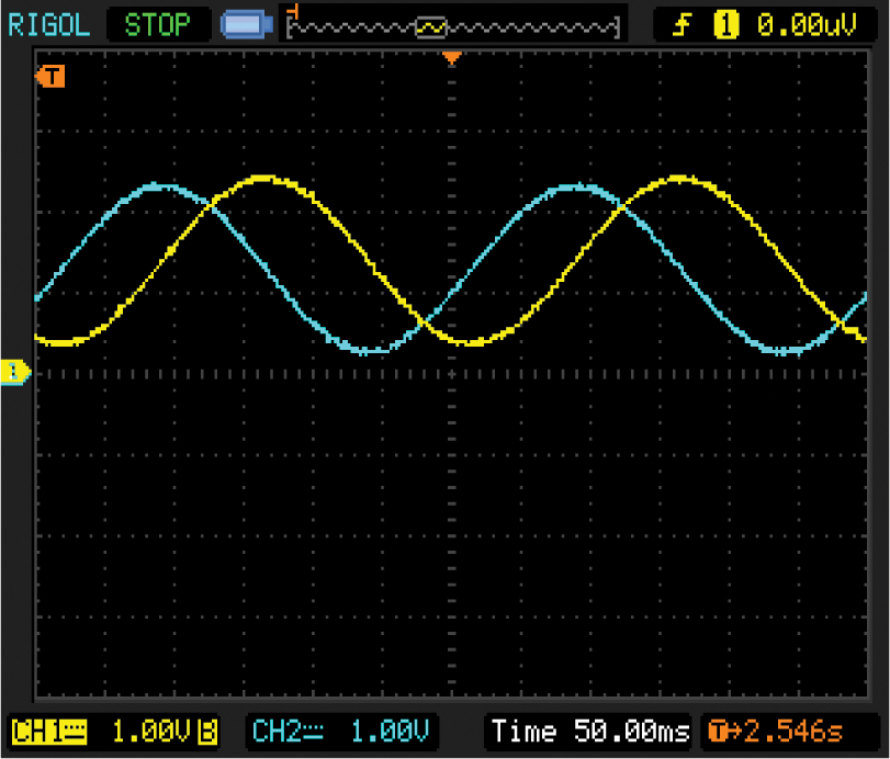
Figure 10: Back EMF waveform of the PMSM
The input DC voltage provided to the inverter and its value is equal to 300 V and the Fig. 11 shows the PWM pulse waveform. These waveforms are used to control the pulse which is given to the switches in the inverter. The technique used to control the pulse is the Sinusoidal PWM technique. Finally, Fig. 12 shows the speed waveform of the motor. The yellow line indicates the reference speed of the motor, which is equal to 1500 rpm and the green line indicates the motor’s actual speed.
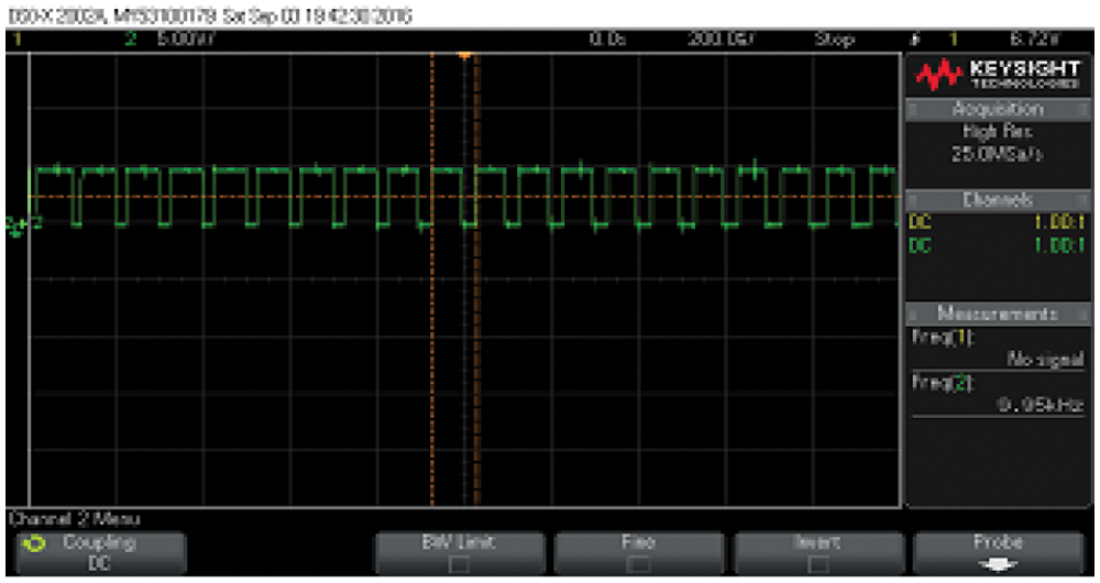
Figure 11: PWM pulse waveform
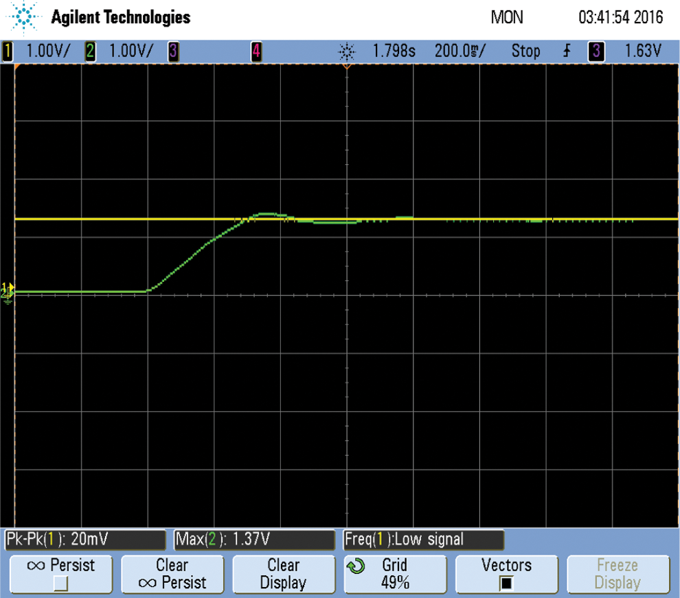
Figure 12: Speed waveform of the motor
Fig. 13 shows the variation of set voltage and actual voltage. The yellow line indicates the reference voltage and the blue line indicates the actual voltage. The speed begins to vary at the time of 5 s and settles at the time of 7 s. Fig. 14 shows the waveform of actual torque and reference torque. Again, the blue line indicates the yellow line indicates the torque and the reference torque. The dip in the waveform occurs due to the load variation.
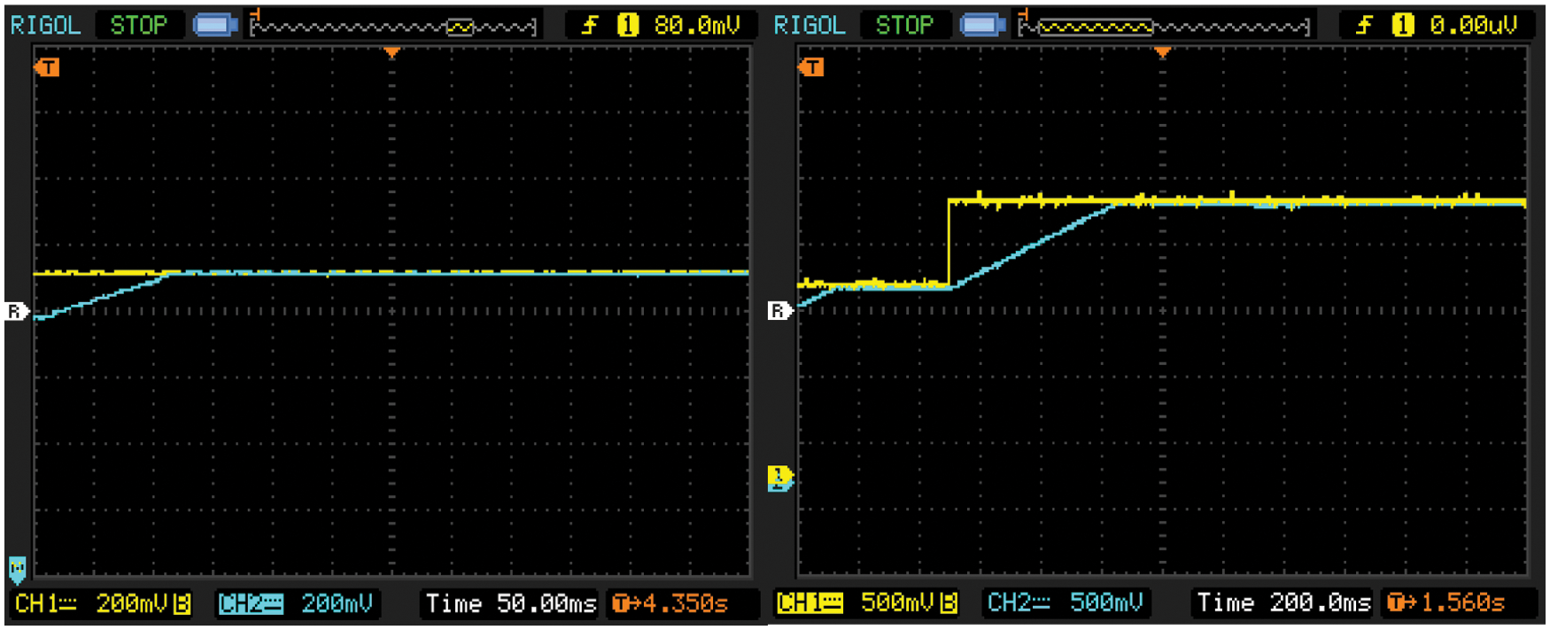
Figure 13: Set DC voltage and actual voltage
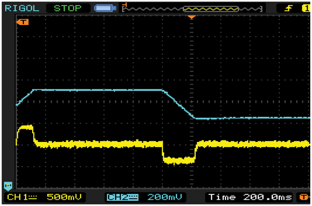
Figure 14: Actual torque and the reference torque
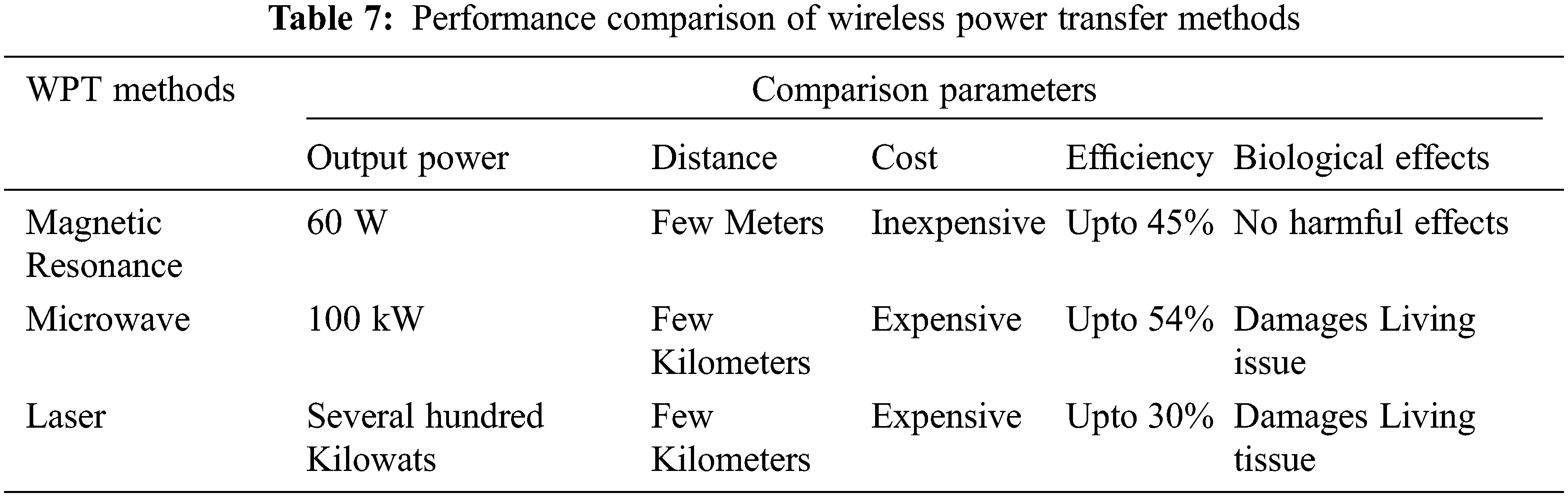
Fig. 15 indicates the waveform of Voltage Source Inverter (VSI) output after providing filter. The Output from VSI will be fed to the PMSM. Tab. 6 shows the comparison of efficiency obtained during the simulation and hardware results and he performance comparison of wireless power transfer methods were tabulated in Tab. 7.
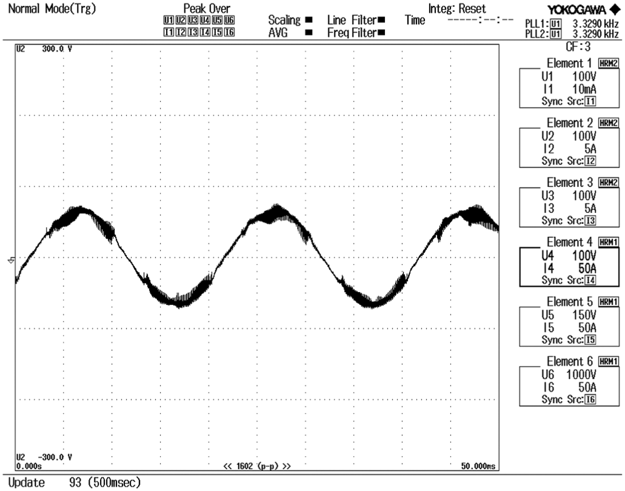
Figure 15: VSI output after filter
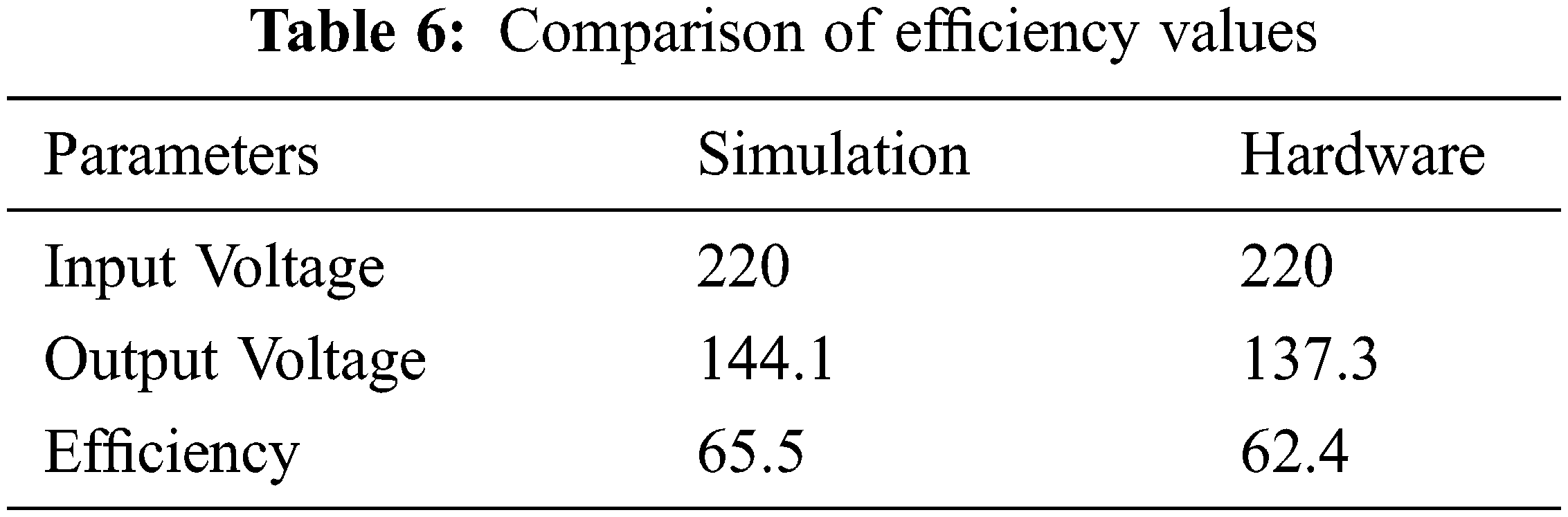
A new L2CL-LCL compensation topology is proposed in this paper. MATLAB simulation is also used to compare the traditional DSLCL system with the proposed L2CL-LCL structure. This topology produces an efficiency of about 95.2% which is better than the traditional system. The input and output power for the conventional framework is 200.1 and 182.4 W respectively. The conventional DSLCL framework’s efficiency is measured as 90.10%. The input and output power for the proposed system is 224.2 and 211.05 W. The efficiencies of various topologies with output power are also tabulated. The output of this topology is fed to an electric vehicle driven by PMSM. The efficiency of the electric vehicle gets improved to about 65.5% which is better than the average efficiency of an electric vehicle. The various parameters of EVs are simulated and results are produced. The experimental analysis results from the theoretical analysis by proving the recommended system’s efficiency is improved.
Acknowledgement: The authors would like to thank APJ Abdul Kalam Technological University and also we like to thank Anonymous reviewers for their so-called insights.
Funding Statement: The authors received no specific funding for this study.
Conflicts of Interest: The authors declare that they have no conflicts of interest to report regarding the present study.
1. Y. Li, J. Hu, X. Li, F. Chen, Q. Xu et al., “Analysis, design, and experimental verification of a mixed high-order compensations-based WPT system with constant current outputs for driving multistring LEDs,” IEEE Transactions on Industrial Electronics, vol. 67, no. 1, pp. 203–213, 2019. [Google Scholar]
2. W. Zhang, S. C. Wong, K. T. Chi and Q. Chen, “Design for efficiency optimization and voltage controllability of series-series compensated inductive power transfer systems,” IEEE Transactions on Power Electronics, vol. 29, no. 1, pp. 191–200, 2013. [Google Scholar]
3. H. H. Wu, A. Gilchrist, K. D. Sealy and D. Bronson, “A high efficiency 5 kW inductive charger for EVs using dual side control,” IEEE Transactions on Industrial Informatics, vol. 8, no. 3, pp. 585–595, 2012. [Google Scholar]
4. A. J. Moradewicz and M. P. Kazmierkowski, “Contactless energy transfer system with FPGA-controlled resonant converter,” IEEE Transactions on Industrial Electronics, vol. 57, no. 9, pp. 3181–3190, 2010. [Google Scholar]
5. W. Zhang, S. C. Wong, K. T. Chi and Q. Chen, “Design for efficiency optimization and voltage controllability of series-series compensated inductive power transfer systems,” IEEE Transactions on Power Electronics, vol. 29, no. 1, pp. 191–200, 2013. [Google Scholar]
6. W. Zhang, S. C. Wong, C. K. Tse and Q. Chen, “Design for efficiency optimization and voltage controllability of series-series compensated inductive power transfer systems,” IEEE Transactions on Power Electronics, vol. 29, no. 1, pp. 191–200, 2014. [Google Scholar]
7. W. Zhang and C. C. Mi, “Compensation topologies of high-power wireless power transfer systems,” IEEE Transactions on Vehicular Technology, vol. 65, no. 6, pp. 4768–4778, 2016. [Google Scholar]
8. A. A. S. Mohamed, A. Berzoy, F. G. N. D. Almeidas and O. Mohammed, “Modeling and assessment analysis of various compensation topologies in bidirectional IWPT system for EV applications,” IEEE Transactions on Industry Applications, vol. 53, no. 5, pp. 4973–4984, 2017. [Google Scholar]
9. L. Zhao, D. J. Thrimawithana and U. K. Madawala, “A comparison of LCL and LC bi-directional inductive power transfer systems,” in Proc. Int. Power Electronics and Application Conf. and Exposition, Shanghai, China, pp. 766–771, 2014. [Google Scholar]
10. L. Wu, B. Zhang and J. Zhou, “Efficiency improvement of the parity-time-symmetric wireless power transfer system for electric vehicle charging,” IEEE Transactions on Power Electronics, vol. 35, no. 11, pp. 12497–12508, 2020. [Google Scholar]
11. J. Hou, Q. Chen, S. C. Wong, K. T. Chi and X. Ruan, “Analysis and control of series/series-parallel compensated resonant converter for contactless power transfer,” IEEE Journal of Emerging and Selected Topics in Power Electronics, vol. 3, no. 1, pp. 124–136, 2014. [Google Scholar]
12. N. Keeling, G. A. Covic, F. Hao, L. George and J. T. Boys, “Variable tuning in LCL compensated contactless power transfer pickups,” in Proc. IEEE Energy Conversion Congress and Exposition, San Jose, CA, USA, pp. 1826–1832, 2009. [Google Scholar]
13. D. Xin, L. Weiyi, L. Yanling, S. Yugang, T. Chunsen et al., “Improved LCL resonant network for inductive power transfer system,” in Proc. IEEE PELS Workshop on Emerging Technologies: Wireless Power, Daejeon, Korea (Southpp. 1–5, 2015. [Google Scholar]
14. H. Hao, G. A. Covic and J. T. Boys, “An approximate dynamic model of LCL-T-based inductive power transfer power supplies,” IEEE Transactions on Power Electronics, vol. 29, no. 10, pp. 5554–5567, 2014. [Google Scholar]
15. J. Zhao, Z. Zhang and Y. Xing, “Design and implementation of double-sided LCL variable compensation topology of MCR-WPT system,” IEEJ Transactions on Electrical and Electronic Engineering, vol. 15, no. 12, pp. 1853–1862, 2020. [Google Scholar]
16. L. Tan, M. Zhang, S. Wang, S. Pan, Z. Zhang et al., “The design and optimization of a wireless power transfer system allowing random access for multiple loads,” Energies, vol. 12, no. 6, pp. 1017, 2019. [Google Scholar]
17. Z. Pantic, S. Bai and S. M. Lukic, “ZCS LCC-compensated resonant inverter for inductive-power-transfer application,” IEEE Transactions on Industrial Electronics, vol. 58, no. 8, pp. 3500–3510, 2011. [Google Scholar]
18. S. Li, W. Li, J. Deng, T. D. Nguyen and C. C. Mi, “A double-sided LCC compensation network and its tuning method for wireless power transfer,” IEEE Transactions on Vehicular Technology, vol. 64, no. 6, pp. 2261–2273, 2015. [Google Scholar]
19. W. Li, H. Zhao, J. Deng, S. Li and C. C. Mi, “Comparison study on SS and double-sided LCC compensation topologies for EV/PHEV wireless chargers,” IEEE Transactions on Vehicular Technology, vol. 65, no. 6, pp. 4429–4439, 2015. [Google Scholar]
20. C. Liu, S. Ge, Y. Guo, H. Li and G. Cai, “Double-LCL resonant compensation network for electric vehicles wireless power transfer: Experimental study and analysis,” IET Power Electronics, vol. 9, no. 11, pp. 2262–2270, 2016. [Google Scholar]
22. Y. Yao, Y. Wang, X. Liu, F. Lin and D. Xu, “A novel parameter tuning method for a double-sided LCL compensated WPT system with better comprehensive performance,” IEEE Transactions on Power Electronics, vol. 33, no. 10, pp. 8525–8536, 2018. [Google Scholar]
23. Y. Xiao, C. Liu, Y. Huang and S. Liu, “Concurrent wireless power transfer to multiple receivers with additional resonant frequencies and reduced power switches,” IEEE Transactions on Industrial Electronics, vol. 67, no. 11, pp. 9292–9301, 2019. [Google Scholar]
24. M. Rozman, A. Ikpehai, B. Adebisi, K. M. Rabie, H. Gacanin et al., “Smart wireless power transmission system for autonomous EV charging,” IEEE Access, vol. 7, pp. 112240–112248, 2019. [Google Scholar]
25. T. A. Huynh and M. F. Hsieh, “Performance analysis of permanent magnet motors for electric vehicles (EV) traction considering driving cycles,” Energies, vol. 11, no. 6, pp. 1385, 2018. [Google Scholar]
26. A. Koran and K. Badran, “Adaptive frequency control of a sensorless-receiver inductive wireless power transfer system based on mixed-compensation topology,” IEEE Transactions on Power Electronics, vol. 36, no. 1, pp. 978–990, 2020. [Google Scholar]
27. A. Kamalaselvan and S. L. Prakash, “Modeling simulation and analysis of closed loop speed control of PMSM drive system,” in Proc. Int. Conf. on Circuits, Power and Computing Technologies, Nagercoil, India, pp. 692–697, 2014. [Google Scholar]
28. S. Li, W. Li, J. Deng, T. D. Nguyen and C. C. Mi, “A double-sided LCC compensation network and its tuning method for wireless power transfer,” IEEE Transactions on Vehicular Technology, vol. 64, no. 6, pp. 2261–2273, 2014. [Google Scholar]
29. P. Pillay and R. Krishnan, “Modeling of permanent magnet motor drives,” in IECON'87: Motor Control and Power Electronics, Cambridge, MA, pp. 289–293, 1987. [Google Scholar]
30. H. Feng, T. Cai, S. Duan, J. Zhao, X. Zhang et al., “An LCC-compensated resonant converter optimized for robust reaction to large coupling variation in dynamic wireless power transfer,” IEEE Transactions on Industrial Electronics, vol. 63, no. 10, pp. 6591–6601, 2016. [Google Scholar]
31. L. Robert, “A comparison of half-bridge resonant converter topologies,” IEEE Transactions on Power Electronics, vol. 3, no. 2, pp. 174–182, 1988. [Google Scholar]
32. W. Zhang and C. C. Mi, “Compensation topologies of high-power wireless power transfer systems,” IEEE Transactions on Vehicular Technology, vol. 65, no. 6, pp. 4768–4778, 2015. [Google Scholar]
33. D. B. Kshatri, S. Shrestha and B. Shrestha, “A brief overview of wireless power transfer techniques,” International Journal of Advanced Smart Convergence, vol. 4, no. 2, pp. 1–5, 2015. [Google Scholar]
 | This work is licensed under a Creative Commons Attribution 4.0 International License, which permits unrestricted use, distribution, and reproduction in any medium, provided the original work is properly cited. |