DOI:10.32604/iasc.2022.023165
| Intelligent Automation & Soft Computing DOI:10.32604/iasc.2022.023165 | |
| Article |
Optimized CUK Converter Based 1Φ Grid Tied Photovoltaic System
Department of Electrical and Electronics Engineering, Sri Ramakrishna Engineering College, Coimbatore, 641022, Tamilnadu, India
*Corresponding Author: S. K. Janarthanan. Email: janarthanansk171@gmail.com
Received: 30 August 2021; Accepted: 24 December 2021
Abstract: Renewable energy-based power generation, particularly photovoltaic (PV)-connected grid systems, has gained popularity in recent years due to its widespread adoption for residential and commercial customers of all sizes, from kilowatt (KW) to megawatt (MW). The purpose of this work is to demonstrate how an efficient CUK-integrated boost converter with continuous current flow may be used to maximise the output of solar arrays. The constant voltage at the converter output is maintained with increased dynamic performance using a Proportional Integral (PI) controller based on a hybrid optimization technique GWO-PSO (Grey Wolf Optimization-Particle Swarm Optimization). This hybrid solution permits accurate and speedy monitoring of the PI controller, which reduces voltage ripples successfully. This system is connected to the 1 grid via a voltage source inverter (VSI). To ensure grid synchronisation, the inverter’s command pulses are generated by a PI controller depending on the grid’s actual power. The Total Harmonic Distribution (THD) of grid current is used to characterize the overall system. The THD is determined to be 1.8 percent with the suggested PI controller and 3.41 percent with the PI controller, and the tracking performance of the GWO-PSO algorithm is 99.8 percent.
Keywords: PV system; CUK integrated boost converter; GWO-PSO PI controller; single phase utility grid
Recent advancements in the power industry have had a considerable impact on the generation of electricity from dispersed renewable sources, as well as the successful integration of those sources (question: Implies who/what?) into the grid [1–3]. The primary objective of a photovoltaic (PV) module is to ensure that each module performs optimally when subjected to varied environmental conditions caused by differences in irradiance levels and changes in ambient temperature. Due to a mismatch in the operating conditions of the PV modules, the output of the PV array is dramatically reduced [4,5]. Thus, new terms must be capable of overcoming the regular and large growth of load demand, as well as the concern over increasing pollution in the environment and the rapid deterioration of conventional resource issues. These dispersed energy sources increase the grid’s decentralisation and fragility, necessitating the use of cutting-edge control systems that comply with grid requirements or standards.
In photovoltaic applications, it is critical to distinguish between the DC converter’s performance and that of the entire system. Additionally, the reduced input current ripples of such converters ensure that the photovoltaic system operates at its peak efficiency, increasing the array’s efficiency. While boost converters are typically used to increase the output of photovoltaic systems, they can also be used to obtain a step-up voltage ratio. While conventional buck-boost converters are capable of increasing and decreasing the voltage conversion ratio, their discontinuous current behaviour limits their ability to run at the maximum achievable Maximum Power Point Tracking (MPPT) without the use of a large decoupling capacitor. While converters such as the CUK, SEPIC, and ZETA provide continuous input and output current and the capacity to increase and decrease voltage, their Maximum Power Point (MPP) tracking performance is restricted by huge input current waves when solar insolation varies around its MPP [6,7].
Current controllers are frequently used in conjunction with converters to maintain stable operation in photovoltaic systems. Numerous controllers described in the literatures each have their own set of advantages and disadvantages. The PI controller employs a trial-and-error approach. It is utilised in industrial applications due to its resilience, but its parameters exhibit sensitivity change and the nonlinear characteristics of dynamic systems [8]. Predictive controllers are less adaptable to changes in the environment. Controllers in sliding mode have problems picking a time-varying surface. While PR controllers have an excellent tracking capability, it requires complex soft computing or metaheuristic algorithms. While hysteresis controllers respond quickly and precisely, their switching frequency is not constant. Researchers are increasingly interested in power regulation in order to adjust for dynamic reactive powers on the grid in addition to transferring active powers. In grid-connected photovoltaic systems, an efficient control is preferred for the simultaneous transfer of actual and reactive electricity. A current controller is used to estimate the reference current required for proper power regulation. Effective power control is contingent upon the controller’s reference current derivation technique. Numerous controllers have been used to regulate converters in the literature [9–13].
In [14–16], several strategies for overcoming the power control issue were described, including P&O, fuzzy inference, genetic algorithm-based Perturb and Observe (P&O) and Particle Swarm Optimization (PSO). While the optimization strategies described above are suitable for nonlinear systems, the sophisticated computation and high delay time requirements considerably increase the controller’s effort. While a single stage voltage source converter (VSC) can be used to connect the solar array to the utility grid, the circuit complexity and presence of higher order harmonics make two-stage power conversion the preferable alternative [17]. Due to its simplicity and greater availability, the conventional VSI (voltage source inverter) is the primary interface device in two-stage grid-connected photovoltaic systems [18]. Fig. 1 illustrates a schematic illustration of grid-connected photovoltaics.
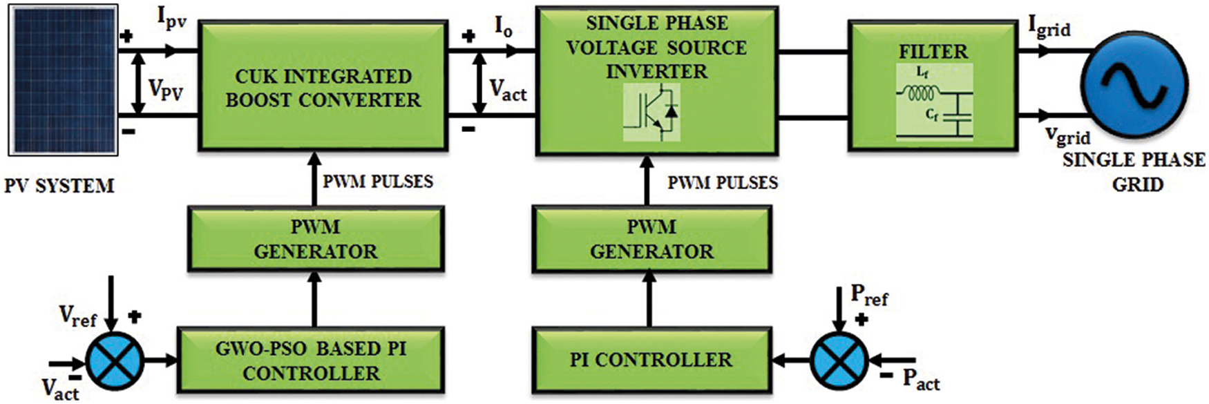
Figure 1: Illustration of grid connected PV system
The purpose of this project is to develop a lossless interface for grid-connected photovoltaic systems. Apart from transmitting useable energy to the single phase grid, our work focuses on obtaining high-quality output energy at the grid. One downside of integrating a photovoltaic array with a single phase grid is that the voltage level at the common coupling point changes (PCC). This variation in voltage is caused by differences in solar insolation. The grid’s voltage and current synchronisation profile dictates the system’s overall effectiveness. The suggested system’s structural topology and control algorithms minimise the ripple associated with photovoltaics and keep grid current harmonics within an acceptable range. The CUK integrated boost converter is used in this application because it has minimal switching losses and a high voltage gain. And the Grey Wolf Optimizer (GWO)-PSO algorithm is chosen because it achieves a more accurate solution at a faster convergence rate. A detailed comparison of the efficiency of various MPPT algorithms (P&O, Fuzzy, PI, and GWO-PSO) is performed. Additionally, the voltage gain of various converters is compared with Single Ended Primary Inductor Converter (SEPIC), BOOST, CUK, and planned Converter Inverter Brake (CIB). The detailed circuit diagram of the proposed converter is discussed in section II. Section II also contains the modeling of PV array, study of operating modes of proposed converter, discussion on GWO-PSO based PI controller, single phase inverter and finally about grid synchronization. The results and discussion come under section III and with section IV remove comma the paper is concluded.
Fig. 2 represents the schematic diagram of a PV integrated grid system. It comprises of a PV array coupled with the CUK integrated Boost converter with one switch, two diodes, two inductors and three capacitors. A high voltage gain is obtained with reduced stress and limited complexity of switching control. The dc-link voltage is regulated by GWO-PSO optimized PI and using this optimization the PI controller parameters is are realized. Irrespective of variations in irradiation and temperature, the converter tries to maintain maximum rated voltage at its output with highest possible efficiency. This voltage is given to single-phase inverter via a DC link split capacitors. Further, the inverter output is coupled with single phase grid via interfacing filter (inductance Lf and capacitance Cf) to remove the ripples in the inverter current caused by converter. Assuming the grid as ideal, the actual grid power is considered as the reference and fed to the PI controller, which analogizes the actual and reference power and the switching sequence for the single phase VSI is generated accordingly.
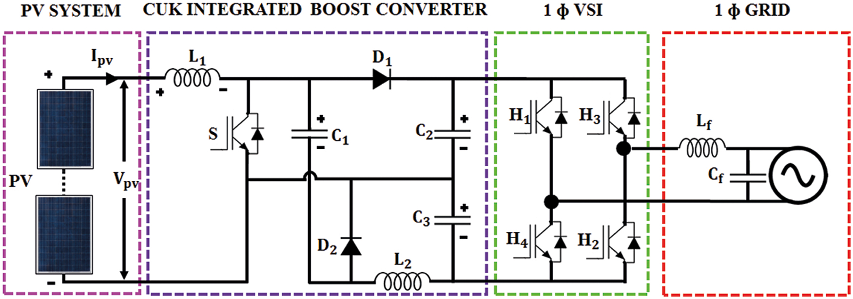
Figure 2: Schematic representation of PV fed CUK integrated Boost Converter system
The pollution free, non requirement of combustible fuels, high maintenance, and noiseless nature make PV based power generation as a significant renewable source. The output voltage of PV panel is
where
The non-linear output characteristics curve given below in Fig. 3 is taken for different insolation between Power (P) and output Voltage (V). The magnitude of the curve varies with partial shading effects (change in temperature and irradiation level). The P-V characteristic has different maximum power points and each is considered as effective at the specific irradiation level.
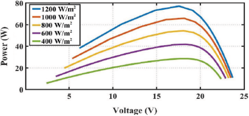
Figure 3: Output characteristics of PV array for T = 25°C
2.2 CUK Integrated Boost Converter
This converter comprises of a conventional boost converter and CUK converter and this hybrid converter includes the merits of both the converters. While integrating, the input-inductor and the switch are kept common and the rest of the components are connected in parallel and so the two capacitors are positioned in the load side.
Fig. 4 illustrates the circuit diagram of proposed CUK integrated boost converter. The higher voltage conversion ratio with single power switch is the advantage of this converter. The operation of the converter is discussed below. The Figs. 5a to 5c represents the various modes of the converter.
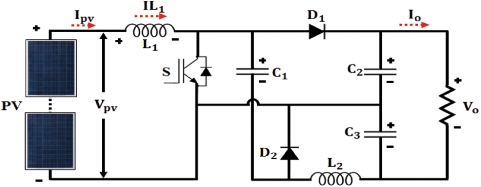
Figure 4: CUK Integrated Boost converter
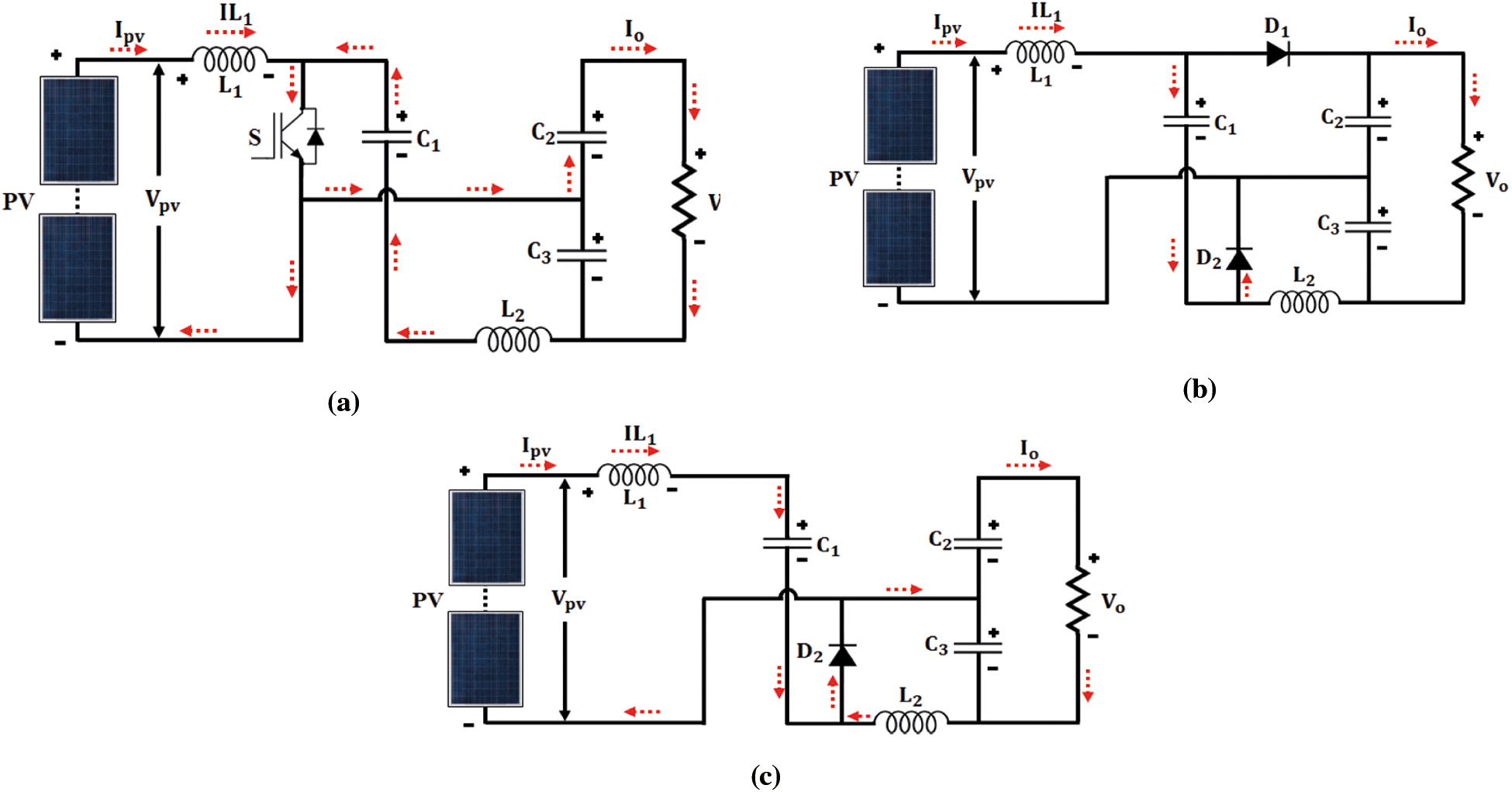
Figure 5: (a): Mode 1 operation (b): Mode 2 operation (c): Mode 3 operation
• Mode 1
As the switch S1 is closed, the capacitor C1 is discharged, inductors L1 and L2 are getting charged and diodes D1 and D2 are in a blocked state because of negative voltages VC2 and VC1,
• Mode 2
The switch S1 is opened between
• Mode 3
The switch S is opened between
The static voltage transfer ratio of the ordinary boost converter is
In CC mode, the converter’s voltage-gain is increased which is the sum of the ordinary converters.
Mean value of the continuous input current IL1
Consider
The value of inductor
Capacitor value of
Expressions of new gain of converter lead to the addition of VC2 and VC3.
where, rL1/R0 = rL2/R0. These values determine the duty cycle of the control pulses.
2.3.1 GWO-PSO Optimized PI Controller for Proposed Converter
PSO is a heuristic algorithm in which moves inside the exploration area to search for the best solution. Further, the data is circulated among the particles. All the particles have their individual position as well as speed. The position denotes the proposed solution by the particle whereas the speed denotes the progressive rate of the molecule position. Optimization is performed by refreshing the position and speed. The position and speed of an ith particle in dth measurement is are updated after “t” iterations are given in (17) and (18).
where w = weight of inertia, C1 & C2 are fixed quantity and
Recently a GWO is developed that is based on the chasing behavior of a grey wolf. The chasing approach and the social commanding chain of a grey wolf are utilized to design and model the GWO algorithm. The model represents the social chain, tracing, enclosing, and assaulting of prey. The social hierarchical models of wolf consider the optimal answer as alpha (α). Then, the next and second most next best answers are called as beta (β) and delta (δ) individually and the remaining solutions are treated as omega (ω). In GWO, the chasing is leaded by α, β, and δ. The ω wolf orders these three wolves for the global maximum. When the grey wolf reaches its prey by chasing, the analytical model of Grey encircling characteristics is given as
where
The parameter values are uniformly changing from two to zero as the iteration is started. The position searching process of the prey (exploration) is performed by splitting the targeted areas, for |A| > 1. The prey obtaining process (exploitation) is performed by limiting the target areas within |A| < 1. The chasing is guided by α entity with a direction from β and δ entities. The GWO algorithm holds local maximum but the A and C parameters aid the optimization from stagnating and extend the search to attain global maximum. Fig. 6 shows the wolf hierarchy.
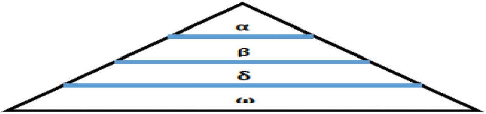
Figure 6: Grey Wolf Optimization
when the operators or expected answers are developed, functional assessments of the new operators are then initiated. This procedure goes on to continue till a termination stage is reached. The GWO-PSO combines Grey Wolf Optimization with Particle Swarm Optimization. The basic concept is to enhance the exploitation capability of PSO using the exploration of GWO so that the exploration and exploitation are balanced to prevent wider local maxima. In this approach, PSO updates the initial populations and the GWO updates the latest refreshed solutions.
The suggested multi-objective GWO-PSO hybrid optimization strategy is depicted in Fig. 7. The GWO parameters are initialised and the initial population is generated using the PSO method. The objective values for each particle are computed and P best, G best are chosen. Now the velocity is calculated, and the search agent’s position is updated accordingly. Now that the non-dominated solutions have been initialised, the leaders are selected. Again, the search agent’s position is updated, as are a, A, and C. Calculate the objective values for all updated search agents and then update the leaders once again. Thus, the ideal answer is determined by the dominant leader.
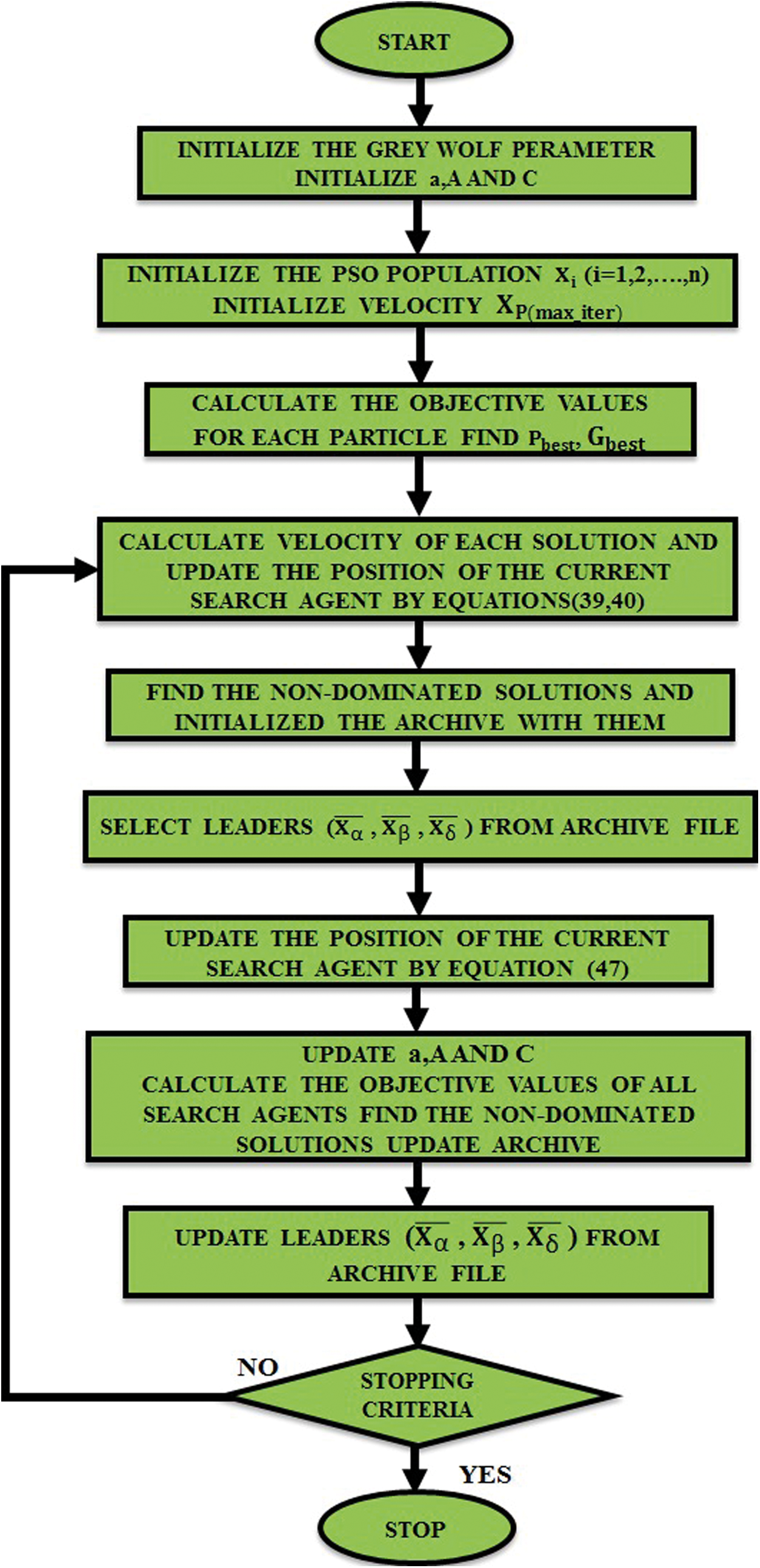
Figure 7: Hybrid GWO-PSO Optimization
GWO-PSO performs multiple objective-based optimization utilising the Pareto fronts idea [19], which enables the discovery of non-dominated solutions. The solutions are then backed up in external “archive” files. The leader for, and the solution of the chasing method are identified using this repository. These leaders guide the remaining search agents toward a promising solution that is closer to the global maximum. It is inconvenient to find the optimal solution in a multiple objective function when selecting a leader; a special strategy is presented below to choose the optimal solution [20,21]. Initial values of PI controller is used by PSO and the parameters such as Wmin (0.4), Wmax (0.9), C1 (1.2), C2 (1.2), lower bound (0, 0, 0), upper bound (266, 266, 266), and population (30) update the objective function.
1. Backup the best non-dominated solution from the archives.
2. Create hyper-cubes of the search region, and place the particles in the hyper-cubes search region based on the objective function.
3. The hunting process selects the minimum crowded hyper-cubes and provides the non-dominated solution as α, β, and δ wolves. The election is performed using a roulette-wheel mechanism with the below arbitrary for every hyper-cubes
where C is a constant (greater than 1) and N is the quantities of solution of the hyper-cubes. The randomness in selecting the hyper-cubes to choose leaders from its answers are improved as the quantity of answers is reduced in the hyper-cubes.
In this paper, GWO-PSO quickly searches for the optimum duty ratio of the converter using PI controller to follow the changes in global MPP power under varying environmental condition with number of search agents: 30 and number of iterations: 100, population size: 200, random vector: 0, 1, and coefficient vector: 0 to 2.
Based on the principle of inverter, the below expressions are derived.
where
The current
Using the PI controller, a quick and stable response with reduced steady state error was obtained. To generate error signal, the instantaneous power is analogized with the reference power which is fed to the PI controller. This output is given to hysteresis to produce the required PWM pulses for the single phase VSI. Fig. 8 shows the control technique used.
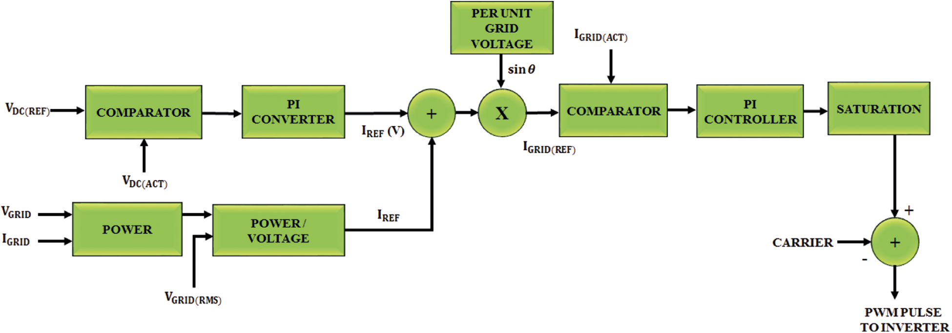
Figure 8: Grid synchronization control technique
The designed system values are provided below in Tabs. 1 and 2. The results shown below are used to measure the converter performance for the variation in insolation, and with and without non-linear load.
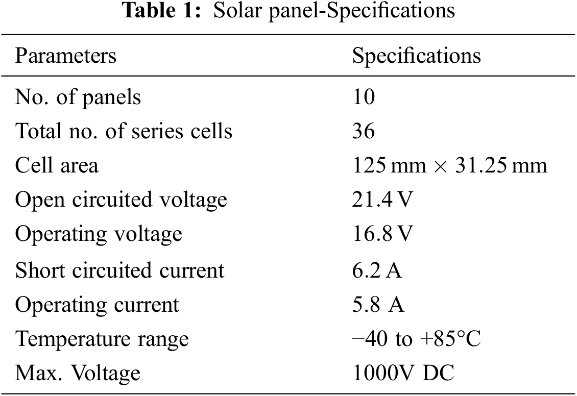
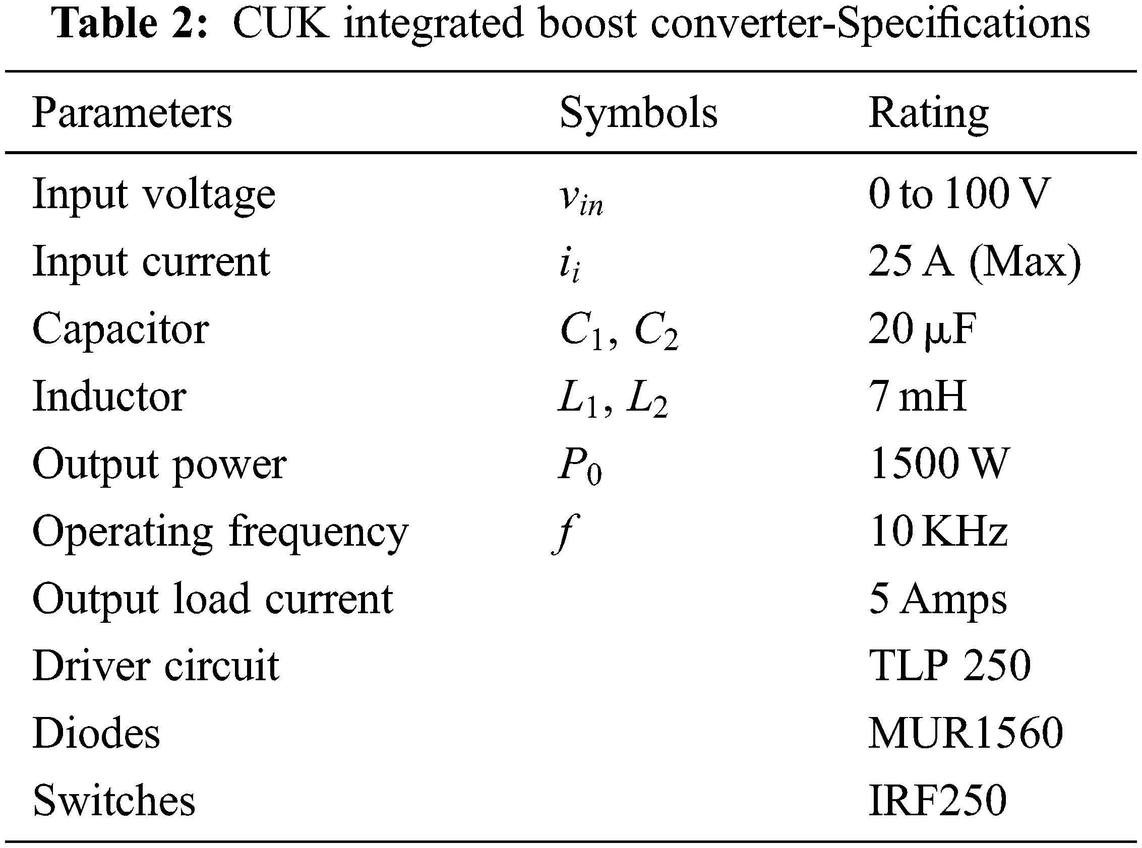
The simulation is performed in time scale for the grid tied PV in MATLAB to ensure the converter’s performance. The power rating of the panel is chosen as 1 KW, 80 V, 50 Hz.
The total model is developed from the sim- power system tool box. A discrete simulation is performed with a sampling period of 20 ms. The goal of this research is to provide fixed power towards the grid even when the input voltage or load varies unknowingly. The irradiance level is manually changed from 800 to 1000 W/m^2 to validate the dynamics of the system, the temperature and partial shading effect are differentiated with the irradiance in real time. The observed change in voltage, current and power from PV are given in Fig. 9a. It is to be noted that the voltage changes from 78 to 80 V which are comparatively smaller than the change in current (17 to 18.5 A) and power (1350 to 1500 W). The analysis is discussed in three sections that correspond to initial behavior and steady state behavior of the converters for the variation in PV irradiation and load. The converter maintains the stable flow of power among the PV and the grid during both steady and dynamic states. A constant power has been given to the grid, as the dc-link voltage which is kept fixed for the solar irradiation of 800 W/m2 as provided in Fig. 9b.
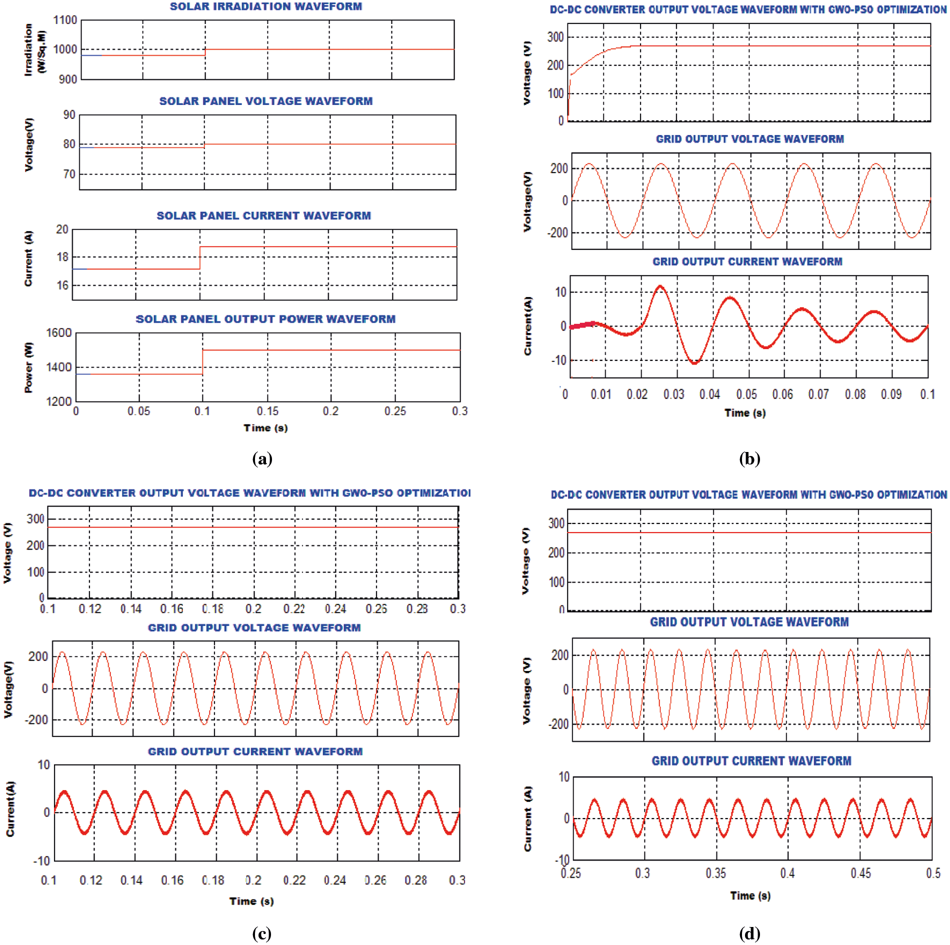
Figure 9: (a): Parameters of the PV module (b): Output of the converter and grid parameters (c): Output of the converter and grid parameters after varying the irradiance (d): Output of the converter and grid parameters after changing load
After 0.1 s, the irradiation is changed from 800 to 1000 W/m2. Even though the irradiation is changed, the voltage and current of the grid remains sinusoidal as shown in Fig. 9c. Further, the link voltage is fixed at
The performances of the conventional and proposed PI controller with GWO-PSO algorithm are measured by estimating the grid current total harmonic distortion (THD) using power analyzer, and are shown in Figs. 10a and 10b. It is observed that grid current THD is
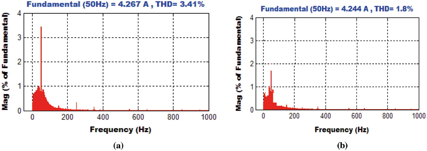
Figure 10: (a): Grid-Current THD using PI controller (b): THD using PI controller optimized with GWO-PSO algorithm
The proposed grid tied PV system is implemented experimentally using
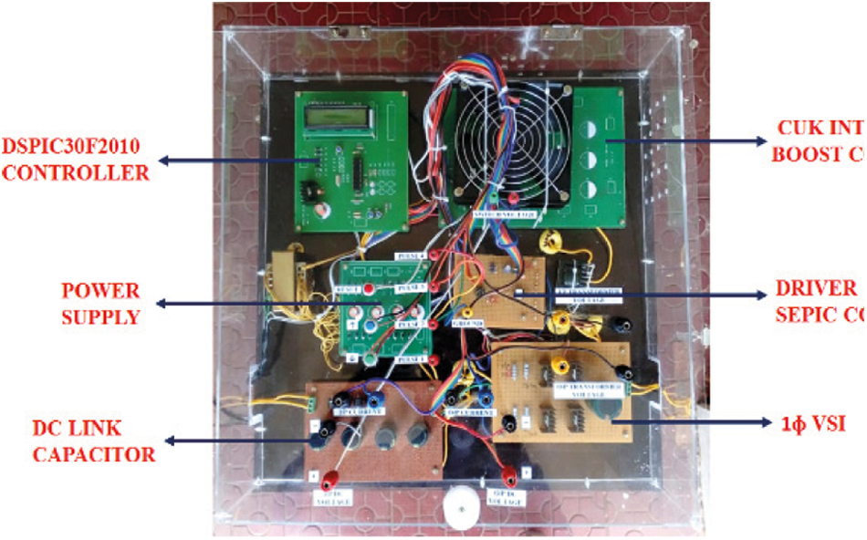
Figure 11: Experimental setup
The simulation results are validated using the prototype implemented by the microcontroller. The responses of the PV array for the change in insolation are shown in Figs. 12a–12c.
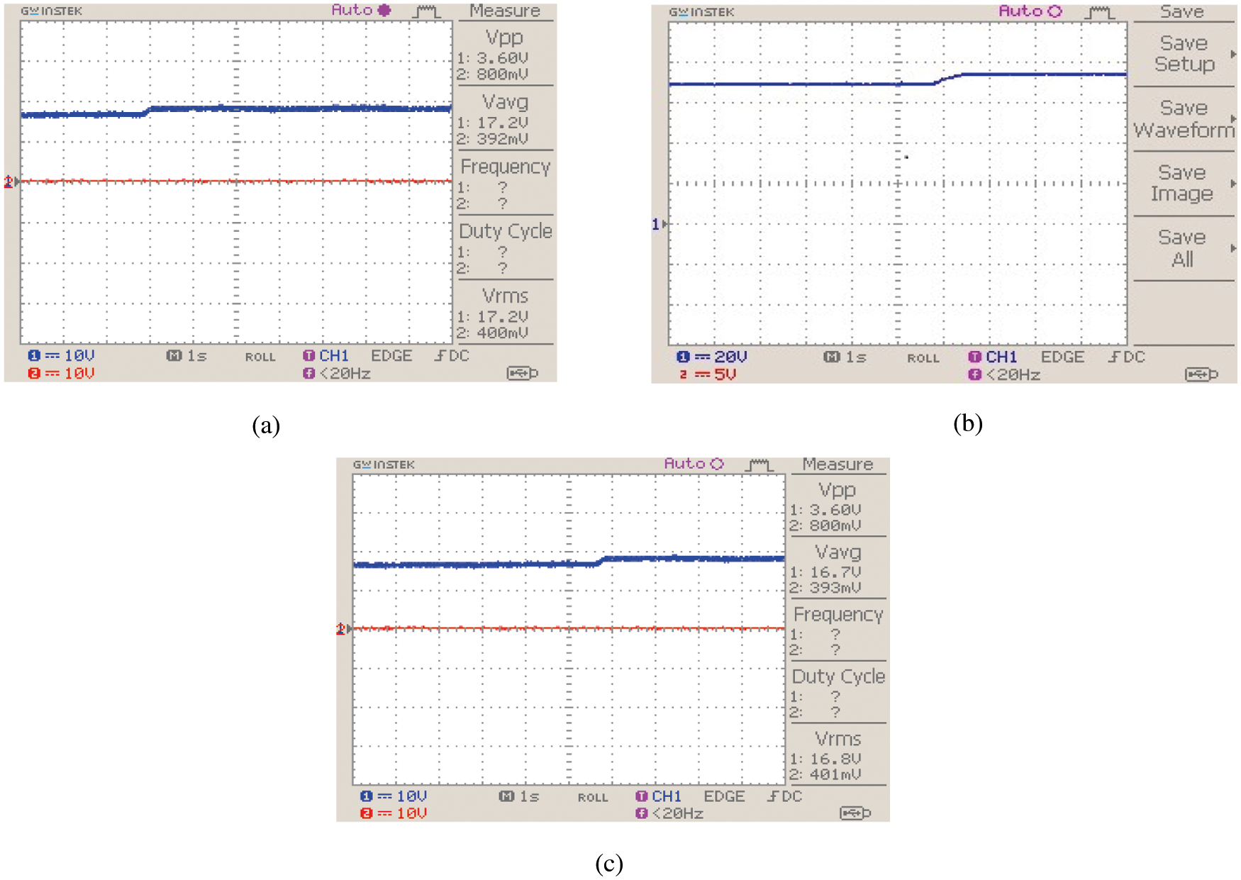
Figure 12: (a): Change in solar irradiance (b): PV array-voltage waveform (c): PV array-current waveform
For 0.55 duty cycle, the response of the proposed controller is depicted in Figs. 13a and 13b. Compared with conventional controller, the maximum peak overshoot error and steady state error are reduced in addition to the reduced response time of the proposed converter using PI controller optimized by PI controller.
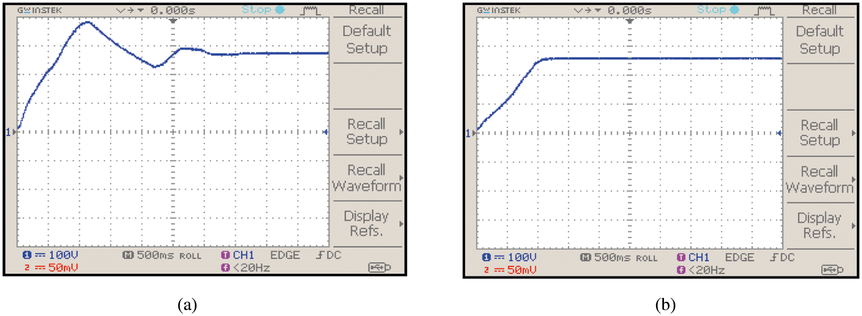
Figure 13: (a): Output voltage of the converter using PI controller (b): Output voltage of the converter with optimized PI controller
The outcome of the PI controller is combined with the sine wave reference extricated from the grid power and fed to the hysteresis controller as the reference power signal. As the reference is taken from the grid, the current output at the inverter will have frequency and phase that will be exactly synchronized with the grid voltage. The zoomed view of grid parameters are represented in Fig. 14b to get the clear visualization.
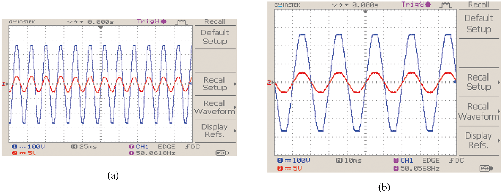
Figure 14: (a): Grid parameters (b): Grid parameters (Zoomed)
The tracking efficiency of proposed GWO-PSO method is compared with P&O, Fuzzy logic and conventional PI in Fig. 15. It reveals that, in comparison the proposed optimization gives extreme efficiency of
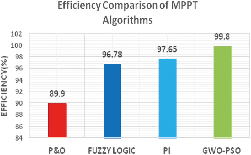
Figure 15: Comparison of MPPT methods
The simulated and hardware results of grid current THD of different controllers are compared in Fig. 16. The GWO-PSO based controller gives minimum value of THD of 1.8 and 2.1 in simulation and hardware. The voltage transfer ratio of CUK Integrated Boost (CIB) converter is compared to SEPIC, CUK, and Boost converters in Fig. 17. A maximum gain of 9 can be achieved with proposed converter while the gain of other converters lies below 5. This shows the better suitability of the proposed CUK integrated Boost converter for grid integration system. The grid current THD by using conventional and optimized PI controller is estimated for the developed experimental setup which includes the power analyzer. It is highlighted in Figs. 18a and 18b. It is found that THD are 3.8% and 2.1% which are slightly higher than that are obtained in simulation but lies within the limit prescribed by IEEE for grid-integrated PV system.
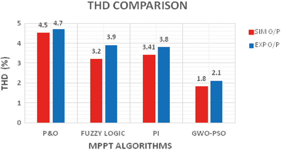
Figure 16: Comparison of simulated and Hardware THD results of MPPPT algorithms
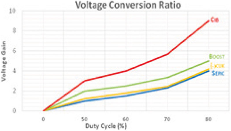
Figure 17: Comparison of gains of converters
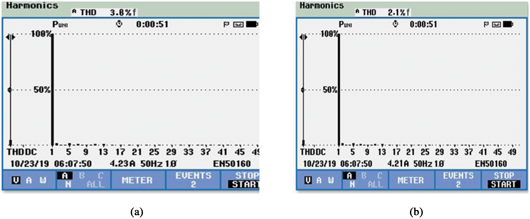
Figure 18: (a): THD using PI controller (b): THD with optimized PI controller
The suggested technique investigates the dynamics and efficacy of the control system in the presence of disturbances that occur in all photovoltaic systems due to the uneven nature of the radiation patterns and temperature variations. The GWO-PSO combination determines the maximum value of the PI controller’s gain parameters in order to adjust the duty ratio depending on the maximum power available at the photovoltaic array. It is observed that the suggested PSO-GWO-PI controller-based CUK integrated Boost converter-fed inverter compensates for harmonics better than a traditional PI controller under a variety of operating situations. The simulation is carried out in MATLAB to highlight the value of rapid simulation speed. The simulated findings validate the suggested system’s performance, which is corroborated by the experimental setup produced. The accurate tracking performance with power fluctuation is visible, indicating that the suggested system and its controller are functional and superior enough to replace the present system. The THD of the suggested configuration with optimised PI controller is 1.8 percent, and the proposed GWO-PSO algorithm has a tracking efficiency of 99.8 percent.
Funding Statement: The authors received no specific funding for this study.
Conflicts of Interest: The authors declare that they have no conflicts of interest to report regarding the present study.
1. R. Wandhare and V. Agarwal, “Reactive power capacity enhancement of a PV-grid system to increase PV penetration level in smart grid scenario,” IEEE Transactions Smart Grid, vol. 5, no. 4, pp. 1845–1854, 2014. [Google Scholar]
2. Y. Bae, T. K. Vu and R. Y. Kim, “Implemental control strategy for grid stabilization of grid-connected PV system based on German grid code in symmetrical low-to-medium voltage network,” IEEE Transactions Energy Conversion, vol. 28, no. 3, pp. 619–631, 2013. [Google Scholar]
3. N. Bader, N. Alajmi, H. Ahmed, G. P. Adam and W. Barry, “Single-phase single-stage transformer less grid-connected PV system,” IEEE Transactions on Power Electronics, vol. 28, no. 6, pp. 2664–2676, 2013. [Google Scholar]
4. T. Shimizu, O. Hashimoto and G. Kimura, “A novel high-performance utility-interactive photovoltaic inverter system,” IEEE Transactions on Power Electronics, vol. 18, no. 2, pp. 704–711, 2003. [Google Scholar]
5. A. Maki and S. Valkealahti, “Power losses in long string and parallel connected short strings of series-connected silicon-based photovoltaic modules due to partial shading conditions,” IEEE Transactions Energy Conversvation, vol. 27, no. 1, pp. 173–183, 2012. [Google Scholar]
6. M. Forouzesh, Y. Shen, K. Yari, Y. P. Siwakoti and F. Blaabjerg, “High efficiency high step-up DC-DC converter with dual coupled inductors for grid-connected photovoltaic systems,” IEEE Transactions on Power Electronics, vol. 33, no. 7, pp. 5967–5982, 2018. [Google Scholar]
7. L. V. Bellinaso, H. H. Figueira, M. F. Basquera, R. P. Vieira, H. A. Gründling et al., “Cascade control with adaptive voltage controller applied to photovoltaic boost converters,” IEEE Transactions on Industry Applications, vol. 55, no. 2, pp. 1903–1912, 2019. [Google Scholar]
8. R. A. Mastromauro, M. Liserre and A. Dell’Aquila, “Control issues in single-stage photovoltaic systems: MPPT, current and voltage control,” IEEE Transactions on Industrial Information, vol. 8, no. 2, pp. 241–254, 2012. [Google Scholar]
9. Y. Singh, I. Hussain, B. Singh and S. Mishra, “Single-phase single-stage grid tied solar PV system with active power filtering using power balance theory,” Journal of the Institution of Engineers (IndiaSeries B, Springer, vol. 99, no. 3, pp. 301–311, 2018. [Google Scholar]
10. Y. Yang, H. Wang and F. Blaabjerg, “Reactive power injection strategies for single-phase photovoltaic systems considering grid requirements,” IEEE Transactions on Industry Applications, vol. 50, no. 6, pp. 4065–4076, 2014. [Google Scholar]
11. A. Datta, R. Sarker and I. Hazarika, “An efficient technique using modified P-Q theory for controlling power flow in a single-stage single-phase grid-connected PV system,” IEEE Transactions on Power Systems, vol. 15, no. 8, pp. 4635–4645, 2019. [Google Scholar]
12. K. Hany and M. Hasanien, “An adaptive control strategy for low voltage ride through capability enhancement of grid-connected photovoltaic power plants,” IEEE Transactions on Power Systems, vol. 31, no. 4, pp. 3230–3237, 2016. [Google Scholar]
13. A. Samir, M. Taha, M. M. Sayed and A. Ibrahim, “Efficient PV-grid system integration with PV-voltage-source converter reactive power support,” The Journal of Engineering, vol. 2018, no. 2, pp. 130–137, 2018. [Google Scholar]
14. S. Fahad, A. JaferMahdi, W. Hu Tang, K. Huang and Y. Liu, “Particle swarm optimization based DC-link voltage control for two stage grid connected PV inverter,” in Int. conf. on power system technology, Guangzhou, China, vol. 6, pp. 2233–2241, 2018. [Google Scholar]
15. R. A. Barbosa, D. A. Souza and A. P. N. Tahim, “Adaptive control of DC microgrid using pi controller and fuzzy inference,” IEEE Conference on PES Innovative Smart Grid Technologies, Latin America, vol. 15, pp. 1–16, 2019. [Google Scholar]
16. L. Zaghba, M. Khennane, A. Borni, A. Fezzani, A. Bouchakour et al., “A genetic algorithm based improve p&o-pi mppt controller for stationary and tracking grid-connected photovoltaic system,” in in proc. Int. Conf. on Renewable and Sustainable Energy, Agadir, Morocco, vol. 7, pp. 1–6, 2019. [Google Scholar]
17. K. Mansfield, “Comparison of single stage and two stage grid-tie inverters,” Electronic thesis and Dissertation, STARS, University of Central Florida, 2019. [Google Scholar]
18. G. Petrone, G. Spagnuolo and M. Vitelli, “A multivariable perturb and-observe maximum power point tracking technique applied to a single-stage photovoltaic inverter,” IEEE Transaction on Industrial Electronics, vol. 58, no. 1, pp. 76–84, 2011. [Google Scholar]
19. C. A. Coello and M. S. Lechuga, “A proposal for multiple objective particle swarm optimization,” Proceedings of the Congress on Evolutionary Computation, vol. 2, no. 6, pp. 1051–1056, 2002. [Google Scholar]
20. B. Han, J. Sheng Lai and M. Kim, “Dynamic modeling and controller design of dual-mode cuk inverter in grid-connected PV/TE applications,” IEEE Transactions on Power Electronics, vol. 33, no. 10, pp. 8887–8904, 2018. [Google Scholar]
21. K. Nathan, S. Ghosh, Y. Siwakoti and T. Long, “A new DC-DC converter for photovoltaic systems: Coupled-inductors Combined Cuk-SEPIC converter,” IEEE Transactions on Energy Conversion, vol. 34, no. 1, pp. 191–201, 2019. [Google Scholar]
 | This work is licensed under a Creative Commons Attribution 4.0 International License, which permits unrestricted use, distribution, and reproduction in any medium, provided the original work is properly cited. |