DOI:10.32604/iasc.2022.024070

| Intelligent Automation & Soft Computing DOI:10.32604/iasc.2022.024070 |  |
| Article |
Contourlet and Gould Transforms for Hybrid Image Watermarking in RGB Color Images
1Department of ECE, Noorul Islam Centre for Higher Education, Kumaracoil, 629180, India
2Department of ECE, Malla Reddy College of Engineering and Technology, Hyderabad, 500001, India
*Corresponding Author: Reena Thomas. Email: reenathomaspaper12@gmail.com
Received: 02 October 2021; Accepted: 03 November 2021
Abstract: The major intention of this work is to introduce a novel hybrid image watermarking technique for RGB color images. This hybrid watermarking algorithm uses two transforms such as Contourlet and Gould transform. The Contourlet transform is used as first stage while the Gould transform is used as second stage. In the watermark embedding phase, the R, G and B channels are transformed using Contourlet transform. The bandpass directional sub band coefficients of Contourlet transformed image are then divided into
Keywords: Contourlet transform; embedding rate; Gould transform; hybrid image watermarking; robustness
Image watermarking [1–3] is a technique where information is hidden on a host image. These watermarking techniques have applications in protecting and verifying the copyright of host image. Today, because to the fast advancement in digital technologies, especially the internet, huge amount of media such as image are transmitted and shared around the world. Protecting and verifying the ownership of the image is a challenging task. Watermarking is an advance solution to ensure the copyright of images. Watermarking system is categorized on the basis of watermark visibility. The watermark will be transparent in a visible watermarking while it is not transparent in an invisible watermarking technique [4–6].
Watermarking can be performed on spatial domain [7–9] as well as frequency domain [10–12]. In spatial domain method, secret data is directly induced on pixel intensities without any transformation in host image pixel intensities. Since the pixel intensities are easily modifiable, these techniques are highly vulnerable to attacks. In a frequency domain scheme, the watermark is induced on the host after applying a transform. These frequency domain methods are more resistant to attacks when compared to spatial domain scheme, because of its less sensitivity to such attacks.
Many researchers are working on image watermarking algorithm [13,14] to improve the performance such as embedding rate, image quality and robustness. The term robustness addresses the capability to recover the watermark even though the image is subjected to various types of spatial attacks. The spatial domain schemes include Histogram Shift [15], Differential Expansion [16] and Predictive Expansion [17]. Frequency domain schemes include transforms such as Discrete Fourier Transform (DFT) [18], Discrete Cosine Transform (DCT) [19] and Discrete Wavelet Transform (DWT) [20]. These transform also uses the decomposition method such as Singular Value Decomposition (SVD) [21], QR Decomposition, Schur Decomposition [22] and LU Decomposition [23].
Initially, the Contourlet transform [24] was proposed using multiscale filtering and block ridgelet transform that works on continuous domain. Later the ridgelet transform was replaced by frequency partitioning and the transform was named as second generation curvelet transform. The Contourlet transform needs an edge detection process and adaptive representation. This Contourlet uses a double filter bank to obtain the sparse representation for smooth contour images. It performs the edge detection process using a transform similar to wavelet. For detecting the Contour segment, it uses a local directional transform.
The multiscale decomposition can be achieved by using Laplacian Pyramid (LP). At each level of Laplacian Pyramid decomposition, a low pass of the original image is generated. In multidirectional filter bank the down sampling the signal
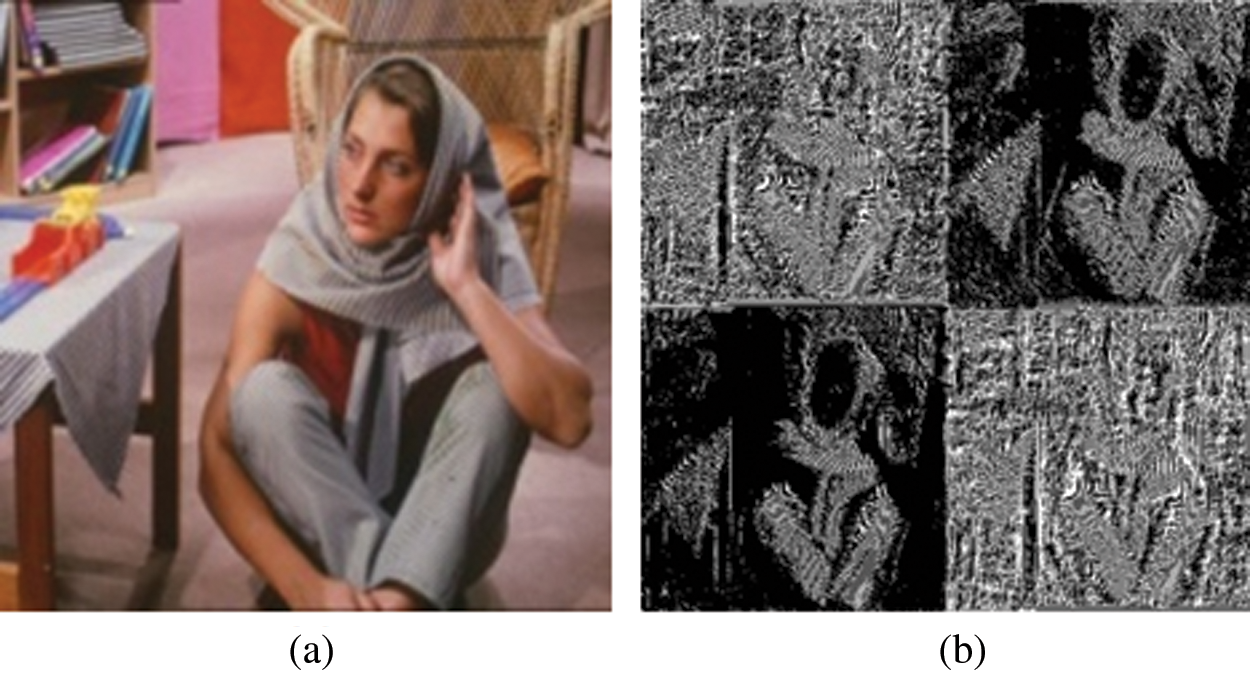
Figure 1: Frequency transformation (a) Barbara image, (b) pyramidal levels
In 2006, Le et al. proposed discrete Gould transform [25]. In this 2D Gould transform a matrix or image
Therefore, the 2D Gould transform for a 2D gray scale image
where
Let f_ij be the pixel in a 2 × 2 subimage in ith row and jth column. In a 2 × 2 subimage the discrete Gould transform coefficients specifies the differencing between the neighbouring pixels. The inverse discrete Gould transform for the transformed image F can be obtained using the relation,
From Eq. (6), if all the Gould coefficients are used for embedding (i.e., all the coefficients are incremented by
3 Proposed Hybrid Watermarking Algorithm
Fig. 2 depicts a detailed flow of embedding process. Let
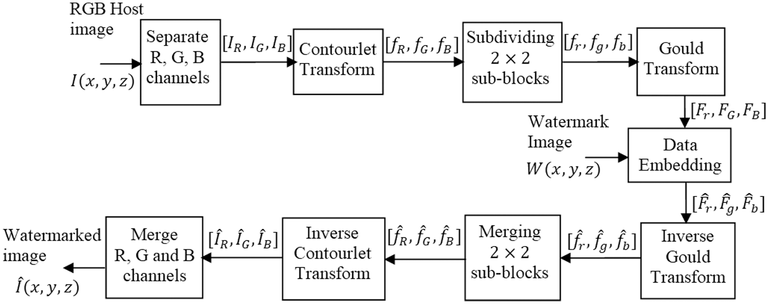
Figure 2: Process flow of proposed watermark embedding scheme
After embedding the watermark bit
Here,
Input: RGB host image
Output: Watermarked image
Step 1: Separate the channels from the host image
Step 2: Obtain the Contourlet transform for the R channel
Step 3: Subdivided the bandpass directional subband Contourlet coefficients
Step 4: Obtain the Gould transform for the
Step 5: Embed the watermark data
Step 6: Obtain the inverse Gould transform for
Step 7: Merge the
Step 8: Obtain the inverse Contourlet transform for
Step 9: Repeat Step 2 to 8 for G and B channels to obtain
Fig. 3 depicts a detailed flow of extraction process. Let
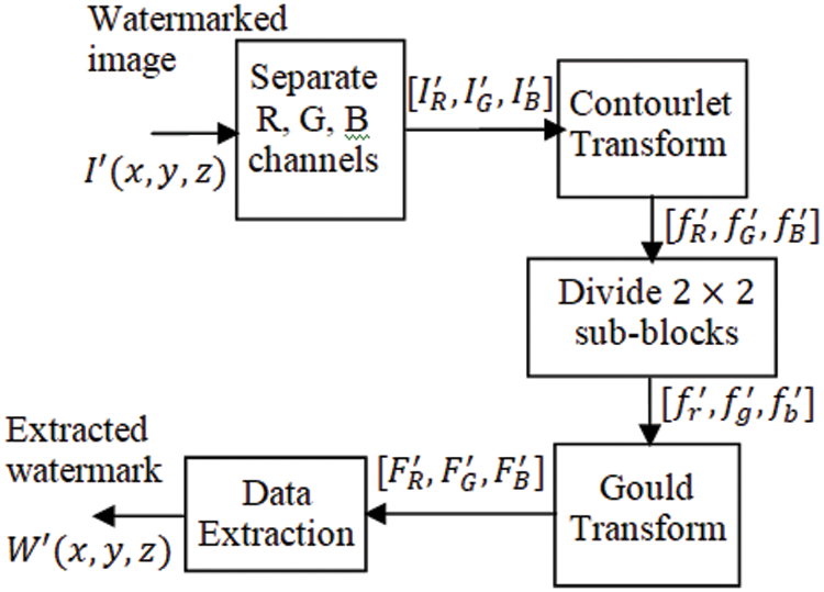
Figure 3: Process flow of proposed watermark extraction scheme
From the Gould coefficients
The algorithm for watermark embedding is given below,
Input: Watermarked image
Output: Extracted watermark
Step 1: Separate individual channels from the watermarked image
Step 2: Obtain the Contourlet transform for the R channel
Step 3: Subdivided the bandpass directional sub-band Contourlet coefficients to
Step 4: Obtain the Gould transform for the
Step 5: Extract the watermark data
Step 6: Repeat 2nd step through 5th step 5 to extract complete watermark data
MATLAB was used to implement the proposed technique with the four test RGB host images shown in Fig. 4. Each of these host images has a dimension of 512 × 512. The test watermark images are also RGB color images each having a size of

Figure 4: Sample host images (a) Lena (b) Barbara (c) Airplane (d) Tiffany
Figure 5: Watermark images (a) Facebook (b) Apple
The embedding rate can be calculated as,
Fig. 6 shows the watermarks extracted from different cover images without applying attacks. The robustness of the proposed hybrid watermarking algorithm was tested using the attacks listed in Tab. 1 and Fig. 7 shows the images that are subjected to such attacks.

Figure 6: Extracted watermarks without attack from different host images (a, b) Lena (c, d) Barbara (e, f) Airplane (g, h) Tiffany

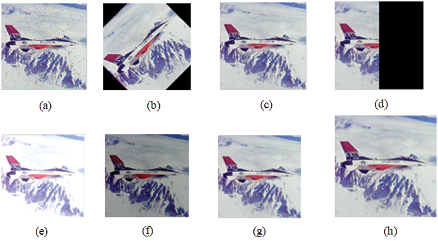
Figure 7: Different types of attacks (a) salt and pepper noise (b) rotation (c) median filtering (d) cropping (e) brightening (f) darkening (g) Gaussian low pass filtering (h) scaling
Figs. 8 and 9 displays the watermarks that have been extracted from the watermarked images that have been applied with attacks listed in Tab. 2. and Fig. 10 shows the watermarked images for the watermark ‘Facebook’ and ‘Apple’.

Figure 8: Extracted watermarks and their NCC values for the RGB host image airplane for different attacks (a) 0.8658 (b) 0.8467 (c) 0.8898 (d) 0.8322 (e) 0.7685 (f) 0.9829 (g) 0.9532 (h) 0.9804

Figure 9: Extracted watermarks and their NCC values for the RGB host image airplane for different attacks (a) 0.9048 (b) 0.8427 (c) 0.9227 (d) 0.9096 (e) 0.8179 (f) 0.9918 (g) 0.9715 (h) 0.9897
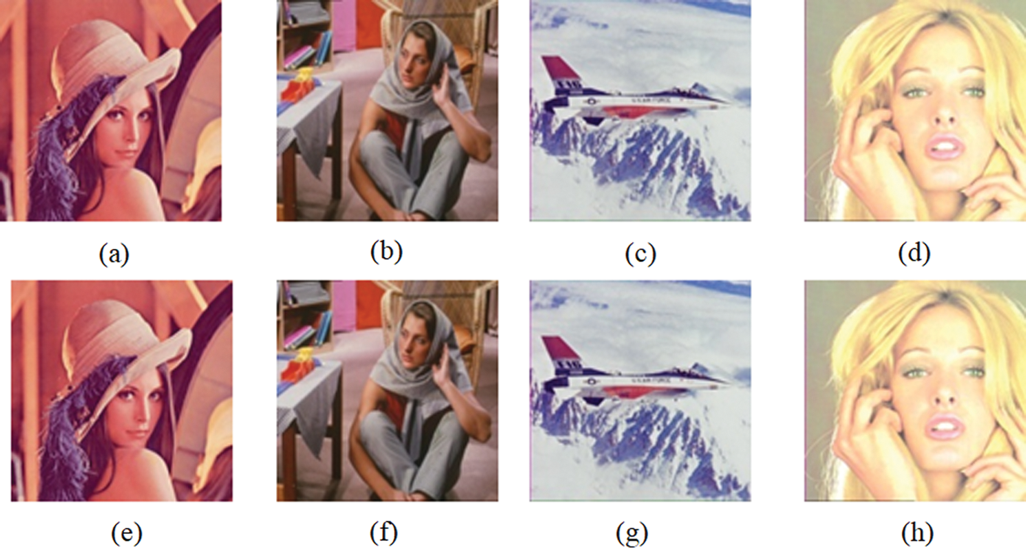
Figure 10: Watermarked images embedded with (a)–(d) Facebook, (e)–(h) Apple

Tab. 2 shows the PSNR, SSIM, and NCC measurement for the proposed method. The average PSNR was found to be 45 dB. The SSIM and NCC was found to be greater than 0.99. Fig. 11 shows the PSNR for varrying embedding capacity in multiple RGB host images. In all the Host images, the Apple watermark provides a higher PSNR than the Facebook watermark. The NCC (Normalized Cross Correlation) metric gives the robustness of the proposed method when subjected to various attacks. The NCC of the proposed method was compared with existing methods such as Improved Hybrid, Tensor decomposition and LU decomposition. Tab. 3 shows the NCC comparison and the proposed algorithm provides higher values than the existing methods.
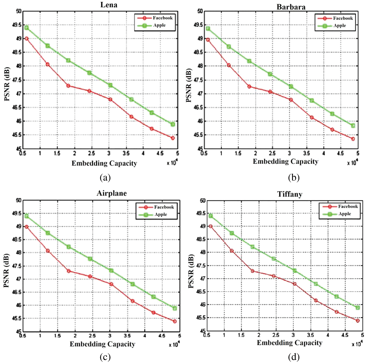
Figure 11: PSNR at Embedding rate for different RGB Host images (a) Lena (b) Barbara (c) Airplane (d) Tiffany

This paper introduced a novel hybrid color image watermarking algorithm which uses Contourlet transform and Gould transform. The color image is initially transformed using Contourlet transform and the bandpass directional sub-band coefficients are again transformed using Gould transform. The secret data is induced on the
Acknowledgement: The author with a deep sense of gratitude would thank the supervisor for his guidance and constant support rendered during this research.
Funding Statement: The authors received no specific funding for this study.
Conflicts of Interest: The authors declare that they have no conflicts of interest to report regarding the present study.
1. X. Zhu, J. Ding, H. Dong, K. Hu and X. Zhang, “Normalized correlation-based quantization modulation for robust watermarking,” IEEE Transactions on Multimedia, vol. 16, no. 7, pp. 1888–1904, 2014. [Google Scholar]
2. A. Khan, A. Siddiqa, S. Munib and S. A. Malik, “A recent survey of reversible watermarking techniques,” Information Sciences, vol. 279, no. 1, pp. 251–272, 2014. [Google Scholar]
3. M. Asikuzzaman and M. R. Pickering, “An overview of digital video watermarking,” IEEE Transactions on Circuits and Systems for Video Technology, vol. 28, no. 9, pp. 2131–2153, 2017. [Google Scholar]
4. M. Asikuzzaman, M. J. Alam, A. J. Lambert and M. R. Pickering, “Imperceptible and robust blind video watermarking using chrominance embedding: A set of approaches in the DT CWT domain,” IEEE Transactions on Information Forensics and Security, vol. 9, no. 9, pp. 1502–1517, 2014. [Google Scholar]
5. M. Asikuzzaman, M. J. Alam, A. J. Lambert and M. R. Pickering, “A blind and robust video watermarking scheme using chrominance embedding,” in Proc. Int. Conf. on Digital Image Computing: Techniques and Applications (DICTA), Wollongong, NSW, Australia, pp. 1–6, 2014. [Google Scholar]
6. M. Kutter and S. Winkler, “A vision-based masking model for spread-spectrum image watermarking,” IEEE Transactions on Image Processing, vol. 11, no. 1, pp. 16–25, 2002. [Google Scholar]
7. B. Li, M. Wang, J. Huang and X. Li, “A new cost function for spatial image steganography,” in Proc. Int. Conf. on Image Processing (ICIP), Paris, France, pp. 4206–4210, 2014. [Google Scholar]
8. V. Sachnev, H. J. Kim, J. Nam, S. Suresh and Y. Q. Shi, “Reversible watermarking algorithm using sorting and prediction,” IEEE Transactions on Circuits and Systems for Video Technology, vol. 19, no. 7, pp. 989–999, 2009. [Google Scholar]
9. X. Li, B. Yang and T. Zeng, “Efficient reversible watermarking based on adaptive prediction-error expansion and pixel selection,” IEEE Transactions on Image Processing, vol. 20, no. 12, pp. 3524–3533, 2011. [Google Scholar]
10. C. H. Chou and K. C. Liu, “A perceptually tuned watermarking scheme for color images,” IEEE Transactions on Image Processing, vol. 19, no. 11, pp. 2966–2982, 2010. [Google Scholar]
11. G. Bhatnagar, Q. J. Wu and B. Raman, “Robust gray-scale logo watermarking in wavelet domain,” Computers & Electrical Engineering, vol. 38, no. 5, pp. 1164–1176, 2012. [Google Scholar]
12. Z. Zhang and Y. L. Mo, “Embedding strategy of image watermarking in wavelet transform domain,” in Proc. SPIE 4551, Image Compression and Encryption Technologies, Wuhan, China, vol. 4551, pp. 127–131, 2001. [Google Scholar]
13. A. K. Singh, “Improved hybrid algorithm for robust and imperceptible multiple watermarking using digital images,” Multimedia Tools and Applications, vol. 76, no. 6, pp. 8881–8900, 2017. [Google Scholar]
14. Y. He, W. Liang, J. Liang and M. Pei, “Tensor decomposition-based color image watermarking,” in Proc. Int. Conf. on Graphic and Image Processing (ICGIP), Hong Kong, China, vol. 9069, pp. 90690U, 2014. [Google Scholar]
15. P. Tsai, Y. C. Hu and H. L. Yeh, “Reversible image hiding scheme using predictive coding and histogram shifting,” Signal Processing, vol. 89, no. 6, pp. 1129–1143, 2009. [Google Scholar]
16. J. Tian, “Reversible data embedding using a difference expansion,” IEEE Transactions on Circuits and Systems for Video Technology, vol. 13, no. 8, pp. 890–896, 2003. [Google Scholar]
17. B. Ou, X. Li, Y. Zhao, R. Ni and Y. Q. Shi, “Pairwise prediction-error expansion for efficient reversible data hiding,” IEEE Transactions on Image Processing, vol. 22, no. 12, pp. 5010–5021, 2013. [Google Scholar]
18. T. K. Tsui, X. P. Zhang and D. Androutsos, “Color image watermarking using multidimensional Fourier transforms,” IEEE Transactions on Information Forensics and Security, vol. 3, no. 1, pp. 16–28, 2008. [Google Scholar]
19. A. Mehto and N. Mehra, “Adaptive lossless medical image watermarking algorithm based on DCT & DWT,” Procedia Computer Science, vol. 78, no. 1, pp. 88–94, 2016. [Google Scholar]
20. P. Bao and X. Ma, “Image adaptive watermarking using wavelet domain singular value decomposition,” IEEE Transactions on Circuits and Systems for Video Technology, vol. 15, no. 1, pp. 96–102, 2005. [Google Scholar]
21. I. A. Ansari, M. Pant and C. W. Ahn, “SVD based fragile watermarking scheme for tamper localization and self-recovery,” International Journal of Machine Learning and Cybernetics, vol. 7, no. 6, pp. 1225–1239, 2016. [Google Scholar]
22. J. Li, C. Yu, B. B. Gupta and X. Ren, “Color image watermarking scheme based on quaternion Hadamard transform and Schur decomposition,” Multimedia Tools and Applications, vol. 77, no. 4, pp. 4545–4561, 2018. [Google Scholar]
23. Q. Su, G. Wang, X. Zhang, G. Lv and B. Chen, “A new algorithm of blind color image watermarking based on LU decomposition,” Multidimensional Systems and Signal Processing, vol. 29, no. 3, pp. 1055–1074, 2018. [Google Scholar]
24. Y. Lu and M. N. Do, “CRISP contourlets: A critically sampled directional multiresolution image representation,” in Proc. SPIE 5207, Wavelets: Applications in Signal and Image Processing, San Diego, California, United States, vol. 5207, pp. 655–665, 2003. [Google Scholar]
25. H. M. Le and M. Aburdene, “The discrete Gould transform and its applications,” in Proc. SPIE 6064, Image Processing: Algorithms and Systems, Neural Networks, and Machine Learning, San Jose, California, United States, vol. 6064, pp. 60640I, 2006. [Google Scholar]
 | This work is licensed under a Creative Commons Attribution 4.0 International License, which permits unrestricted use, distribution, and reproduction in any medium, provided the original work is properly cited. |