DOI:10.32604/iasc.2022.022907
| Intelligent Automation & Soft Computing DOI:10.32604/iasc.2022.022907 | |
| Article |
ANN Based Reduced Switch Multilevel Inverter in UPQC for Power Quality Improvement
1Department of EEE, R. M. K. Engineering College, Chennai, 601206, India
2Department of EEE, Velammal Engineering College, Chennai, 600066, India
*Corresponding Author: Y. Alexander Jeevanantham. Email: alexanderjeevanantham2021@gmail.com
Received: 22 August 2021; Accepted: 03 November 2021
Abstract: A unified power quality conditioner (UPQC) plays a crucial role in the Power quality improvement of a power system. In this paper, a reduced switch multilevel inverter is with artificial neural network, soft computing technique control is proposed for UPQC. This proposed topology is employed for the mitigation of various power quality issues such as voltage sag, voltage swell, power factor, harmonics, and restoration time of voltage compensation. To show the enriched performance of the proposed topology comparative analysis is made with other two topologies of UPQC such as Conventional UPQC and UPQC using cascaded H bridge (CHB) five-level Inverter. All configurations are analysed using Matlab with variable nonlinear loads to analyse the performance during the conditions mentioned above.
Keywords: Power quality; unified power quality conditioner; cascaded H bridge; reduced switch multilevel inverter; artificial neural network
In recent days, consumers and electric utilities like drives, power converters are concentrating on electric power quality [1,2]. Power quality is a significant issue in a distribution network. It is characterized as a nature of power; i.e., it is an idea that is utilized to depict the purity of the transferred energy. In the distribution generation, nonlinear and unbalanced loads develop an abundance of power quality (PQ) problems in the power distribution system [3]. The significance of the power quality issues in the distribution system is the uncharacteristic behaviour of end equipment’s, upsurge of loss, reduced efficacy, electromagnetic nosiness with the neighbouring, and abbreviate the lifetime of the organization [4,5]. Subsequently, that to overcome these PQ (power quality) issues modern power systems implement some compensation devices like dynamic voltage restorer (DVR) [6], distribution static synchronous compensator (D-STATCOM) [7], unified power flow controller (UPFC) [8] and unified power quality conditioner (UPQC) [9]. Yahiya et al. discussed the power quality enhancement with the aid of various methods, which reveals the enriched performance of UPQC [10]. A complete literature survey on the unified power quality conditioner (UPQC) to enrich the quality of electric power at distribution stages [11]. Nagarajan et al. made a detailed survey on various power quality problems and various types of flexible AC transmission system (FACTS) devices with recent technology. The elaborated survey explains the compensation property of UPQC for all power quality issues [12]. UPQC using artificial intelligent fuzzy logic controller (FLC) was analyzed and validated its improved performance with the comparison of conventional proportional integral controller (PIC).
Most of the described configurations of UPQC in the literature are established with traditional two-level inverter [13]. Still, it has a drawback augmented switching losses and harmonic content henceforth as an alternate, Multilevel inverter (MLI) configuration is applied in recent days. The MLI configurations utilized for the expansion of UPQCs is neutral point diode clamped (NPC) and cascaded H bridge MLI [14–16]. Dhote et al. investigated the use offive-level neutral point clamped UPQC in a distribution system to diminish PQ issues. Comparative analysis of NPC-UPQC over conventional UPQC, under various balanced three phase non-linear loading conditions for three phase distribution system, validates the PQ improvement by MLI in UPQC [17]. The survey observed that multilevel inverter with improved control techniques results in improved quality power.
Furthermost generally utilized topologies of a multilevel inverter are diode clamped configuration, flying capacitor type configuration and cascaded configuration [18,19]. In cascaded configuration, the number of switching devices gets increased [20]. In flying capacitor configuration, diverse stages are created in the output voltage by addition or subtraction of the capacitor voltages. Numerous methodologies have been made to defeat these detriments, among that lessening in the number of switches in MLI results in the minimum number of devices and simple switching [21–23]. In this article, reduced switch multilevel inverter-based UPQC with ANN control technique is proposed for analysis. ANN processes data in parallel, so it is faster than traditional systems and intelligent system that process data sequentially. Hence, in this analysis ANN is proposed for fast response, which is mandatory for harmonic mitigation. Performance of the proposed system is compared with the conventional and CHB five-level Inverter based UPQC.
The paper is structured as follows. Section 2 will explain the operation of UPQC. The Conventional Inverter-based UPQC, CHB five-level Inverter-based UPQC, and the proposed systems are explained in Section 3. Section 4 gives the simulation results and its comparison followed by the conclusion in Section 5.
The Fig. 1 shows the block diagram of UPQC which is made with couple of voltage source Inverter based active filters linked back-to-back by a common dc link. The inverter associated in shunt amid the load performs like a shunt active power filter (SAPF) remunerates load current harmonics while sustaining up the dc interface voltage consistent. Another inverter is associated in series to the network and keeps up the load voltage steady. Consequently, UPQC is equipped for enriching the power quality at the PCC in the power framework. Therefore, it is one of the good solutions for the electrical utility that is sensitive to voltage harmonics.
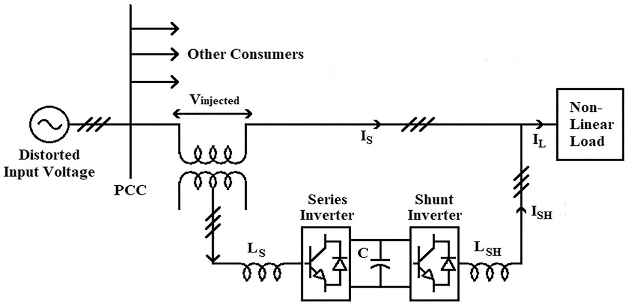
Figure 1: Basic block diagram of UPQC
2 Inverter and Control Circuits of UPQC
The UPQC control unit is split by two-segment as series and shunt filter control [24]. The controllers are made by synchronous reference frame theory-based control and feedback control theory. The comparison between conventional UPQC, Five level CHB Inverter based UPQC and reduced switch multilevel inverter based UPQC with ANN-based control technique for the series part is explained in the following sections.
2.1 System A: Traditional Inverter Based UPQC
The circuit has been implemented with two voltage source inverters. One converter will act as the series inverter and the other will act as a parallel inverter in this case both the Inverters are controlled by hysteresis controller and PI controller has been used for maintaining the DC link voltage.
2.1.1 Controller for Shunt Filter of UPQC
Fig. 2 shows the shunt part control circuit of UPQC. It is set up by utilizing feedback control methods, in which three-phase current reference is appraised by means of estimated input current. Foremost, the input current is transformed to dq0 frame by park transformation using phase locked loop (PLL). For synchronization of the control circuit with the system voltage, the PLL is employed. The dq0 form of source current, the segment of quadrature current designates the quantity of reactive power mandatory, consequently, it has to make as nil, and therefore it is straightforwardly set as reference. The direct axis segment of input current has both fundamental components and harmonic term. The harmonic element must be removed from the input current, and it is done by means of a high pass filter. In addition, shunt path is accountable for sustaining DC link voltage at its anticipated value which is accomplished by means of a PI controller. It is deducted from the direct axis. The quantities in d-q are transformed to the a-b-c frame by inverse park transformation. To diminish the reactive segment and harmonic segment, the processed ISabc is multiplied with a gain of K, which acts as a reference signal (ISabc*) for the switching scheme [25].
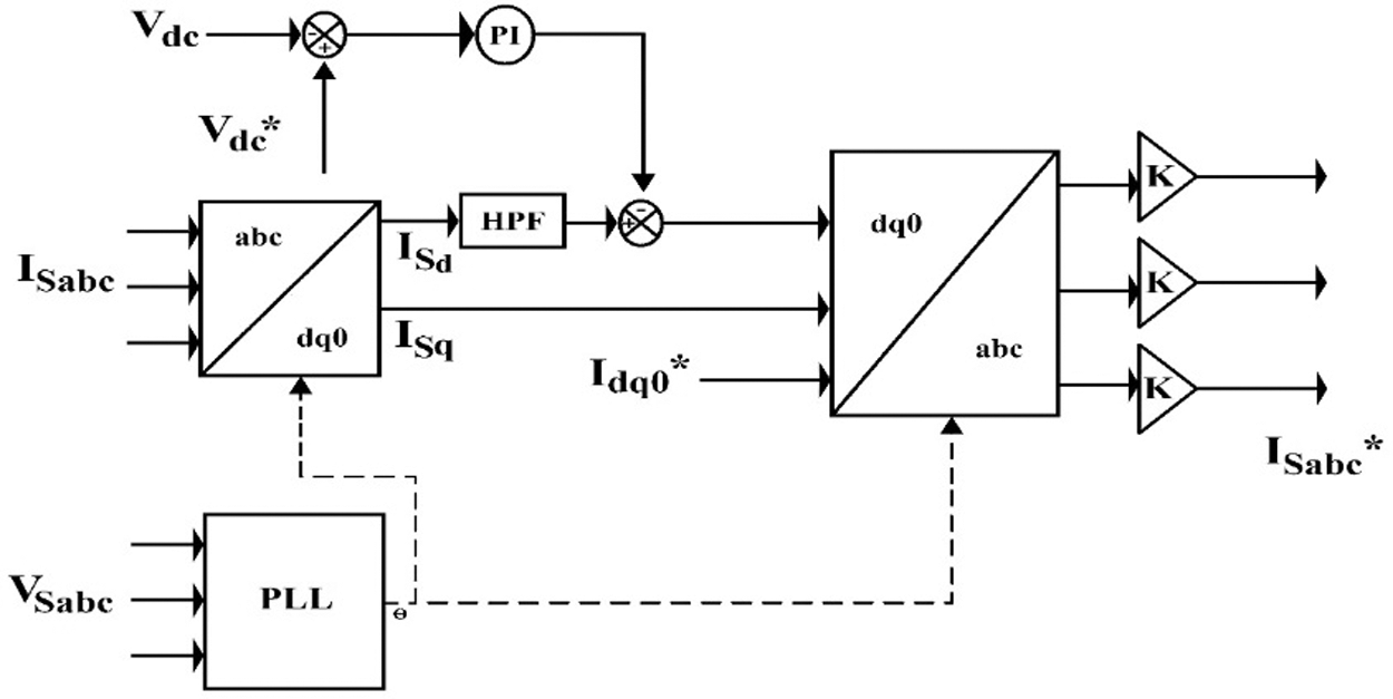
Figure 2: Controller for shunt filter of UPQC
2.1.2 Controller for the Series Filter of UPQC
In series filter circuit, segregated phases are employed. Then this segregation results in zero-sequences or load voltage unbalances. Consequently, the control circuit is also mandatory to lessen unbalance in voltage. Fig. 3 displays the control circuit of modified SRF for the series part of UPQC. In this circuit, an extra error amplifier is employed to lessen the load voltage unbalances. Load and source voltage are act as inputs to the control block. Park transformation is applied in both source and load voltages to convert into a dq0 frame. The d-q segments of the load and source voltage are in contrast with the reference and processed by the PI controller to amplify the error. In this altered controller further PI controller is employed for diminish the load voltage unbalances; the PI controller input is an error amid the zero sequence segment of load voltage with its reference. All PI controller outputs are passed via the reverse park transformation block for producing the three-phase reference voltage (VLabc*) and it is given as PWM for generating the desired gate pulse.
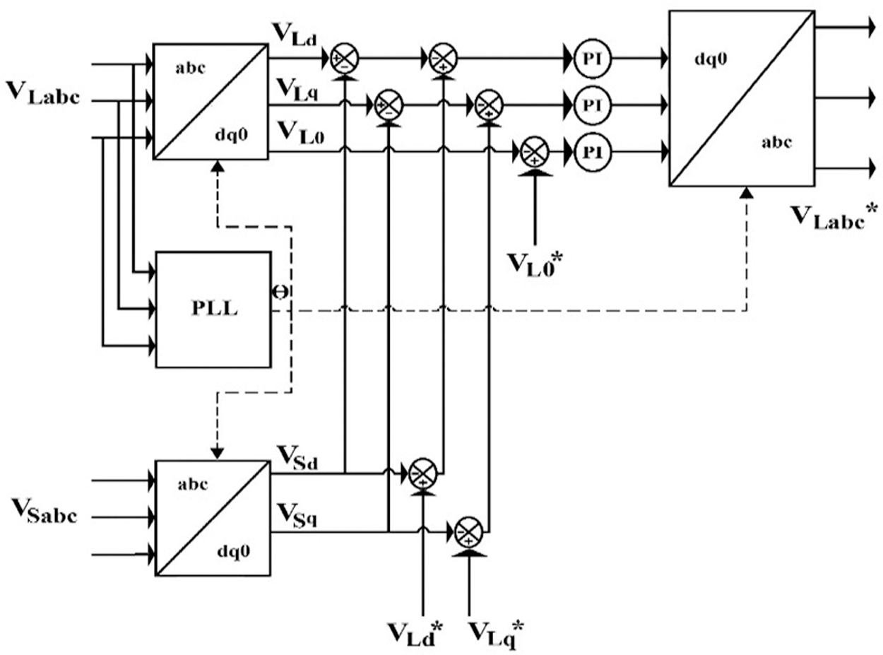
Figure 3: Controller for a series filter of UPQC
2.2 System B: Cascaded Five Level Inverter Based UPQC
The UPQC is made by utilizing two cascaded H-bridge inverters to achieve five-level output. Source for two inverters is attained with the help of two capacitors in a DC link. An entire control system is similar to conventional PI-based UPQC with a two-level inverter, excluding inverter switching. Instead of hysteresis current controller in this topology pulse width modulation is employed to switch the inverter. The Simulation model of the cascaded H bridge in a UPQC is shown in Fig. 4.
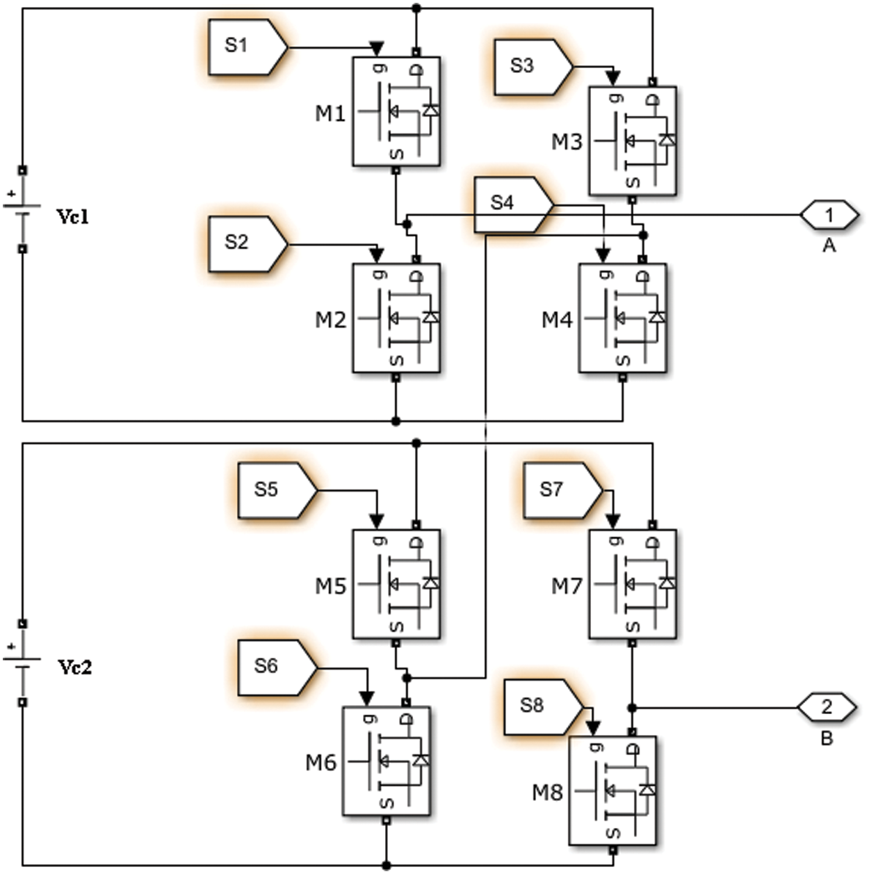
Figure 4: Simulation model of cascaded H bridge
In Fig. 4, Vc1 and Vc2 are the voltage across two capacitors connected in the DC link. S1-S8 are the switching pulses from the PWM circuit. It is an inverter circuit for a single-phase. Similarly, inverter circuits are connected with other phases to develop three-phase compensation signals.
2.3 System C: Modified Reduced Switch Multilevel Based UPQC with ANN Controller
In cascaded H-Bridge inverter topology, the quantity of switches required is more. In this analysis modified reduced switch topology of an inverter is proposed in UPQC along with ANN control Technique for series Inverter. Modified diminished switch MLI method has two switches for level selection and a normal H-Bridge for polarity selection. Fig. 5 depicts the proposed reduced switch multilevel inverter. In Fig. 5, S1 and S2 are the switches applied for source/level selection while other switches are employed for polarity selection.
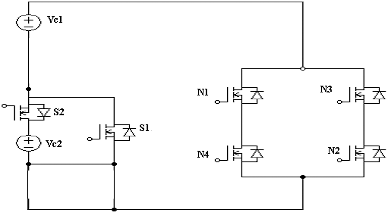
Figure 5: Reduced switch multilevel inverter
The switching logic of the proposed inverter to attain five-level output is as follows.
• Switches S1, N1, and N2 are turned ON to attain +Vc1
• Switches S2, N1, and N2 are turned ON to acquire +(Vc1+Vc2)
• Switches S1, N3, and N4 are turned ON to acquire −Vc1
• Switches S2, N3, and N4 are turned ON to acquire −(Vc1+Vc2)
From Fig. 5, it is noted that the proposed configuration minimizes two switches for five-level output, consequently, the three-phase proposed MLI minimizes six switches. Decrease in the quantity of switches not just reduces the cost and size of the circuit for switches, along it minimizes driver circuits, isolation circuits, and protection circuits for six switching devices. Hence the proposed inverter minimizes the cost and size of the circuit by improving power quality.
To attain improved power quality, in this topology Artificial neural network controller is proposed instead of a PI controller, to produce reference voltage for PWM control in series control.
2.4 Artificial Neural Network Controller
The employment of the feed-forward neural network is made to produce reference load voltage of Vd*, Vq* in series control. The ANN is trained with the help back propagation algorithm of the mean square error (MSE) amongst the output and desired value. When the MSE performance function is used, Levenberg-Marquardt is a training approach that yields faster convergence [26,27]. Therefore, in this analysis, the Levenberg-Marquardt method is employed to train the network, which trains the network with minimum time. The network training set is produced offline with the help of data attained from the PI controller-based system. In this research to train ANN, 11, 65, 594 samples are taken to get the accurate output. A three-layer neural network is framed with the input, hidden and output layer, as depicted in Fig. 6.
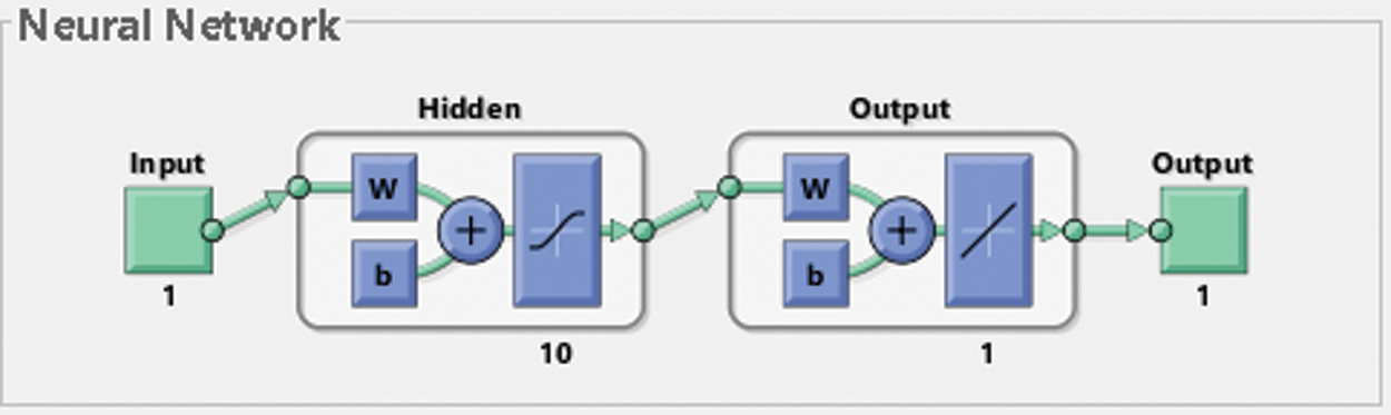
Figure 6: Structure of neural network
The hidden layer is designed with ten neurons to achieve minimum processing time. ANN employed in UPQC system converges training with MSE of 3.3 × 10⁻⁸ in 3.35 s with 137 epochs. This trained ANN is proposed in UPQC to improve power quality in the distribution system.
3 Simulation Results and Analysis
Various topologies of UPQC using PI and ANN controller are developed and using MATLAB/2018a. Performance of each configuration is analysed under sag and swell conditions in the aspects of voltage compensation, restoration time for compensation, Total harmonic distortion, and Power factor. Performance of power system without UPQC under swell and sag condition are shown in Figs. 7 and 8.
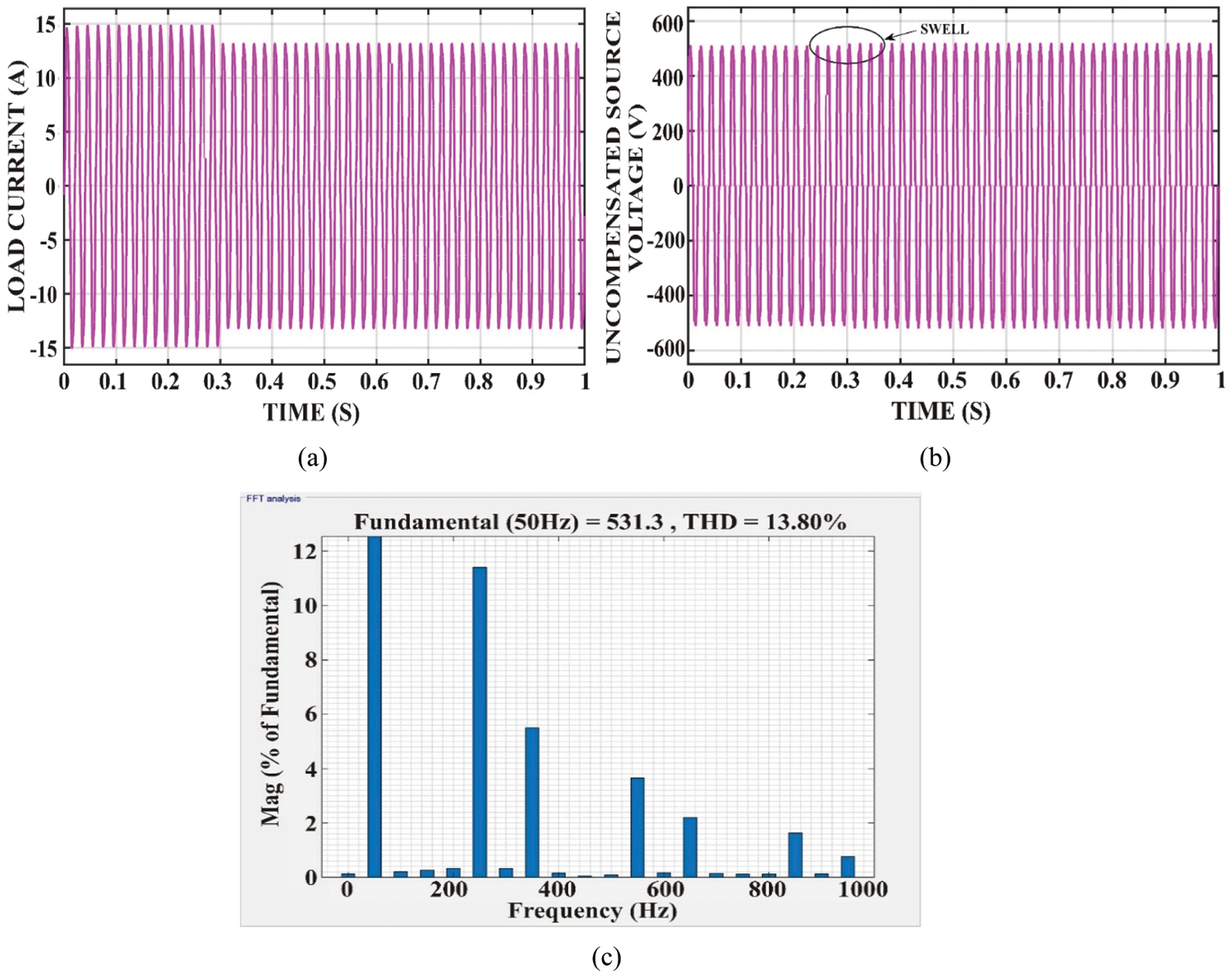
Figure 7: Performance of power system without UPQC under swell (a) load current (b) uncompensated source voltage (V) (c) THD
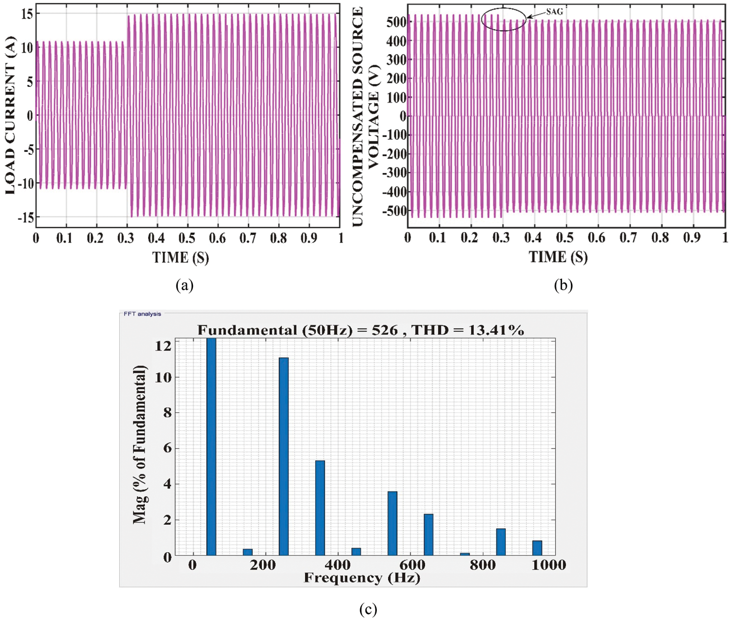
Figure 8: Performance of power system without UPQC under sag (a) load current (b) uncompensated source voltage (V) (c) THD
From Figs. 7 and 8, it is noted that 26 V is dropped during sag condition, while 9.5 V is raised during the swell condition. THD under sag and swell of the system without UPQC, are 13.8% and 13.41% respectively. In this paper, power quality improvement using various topologies under sag condition is presented in the form of figures and tables, while power quality improvement under swell condition is presented in tables.
Performance of UPQC with conventional inverter is shown in Fig. 9. From Fig. 9, it is noted that voltage drop during sag is 4 V, 22 V is compensated during sag condition with help of UPQC. Harmonic distortion in voltage during sag condition is reduced to 4.41%. THD is controlled within the IEEE standard with the aid of UPQC.
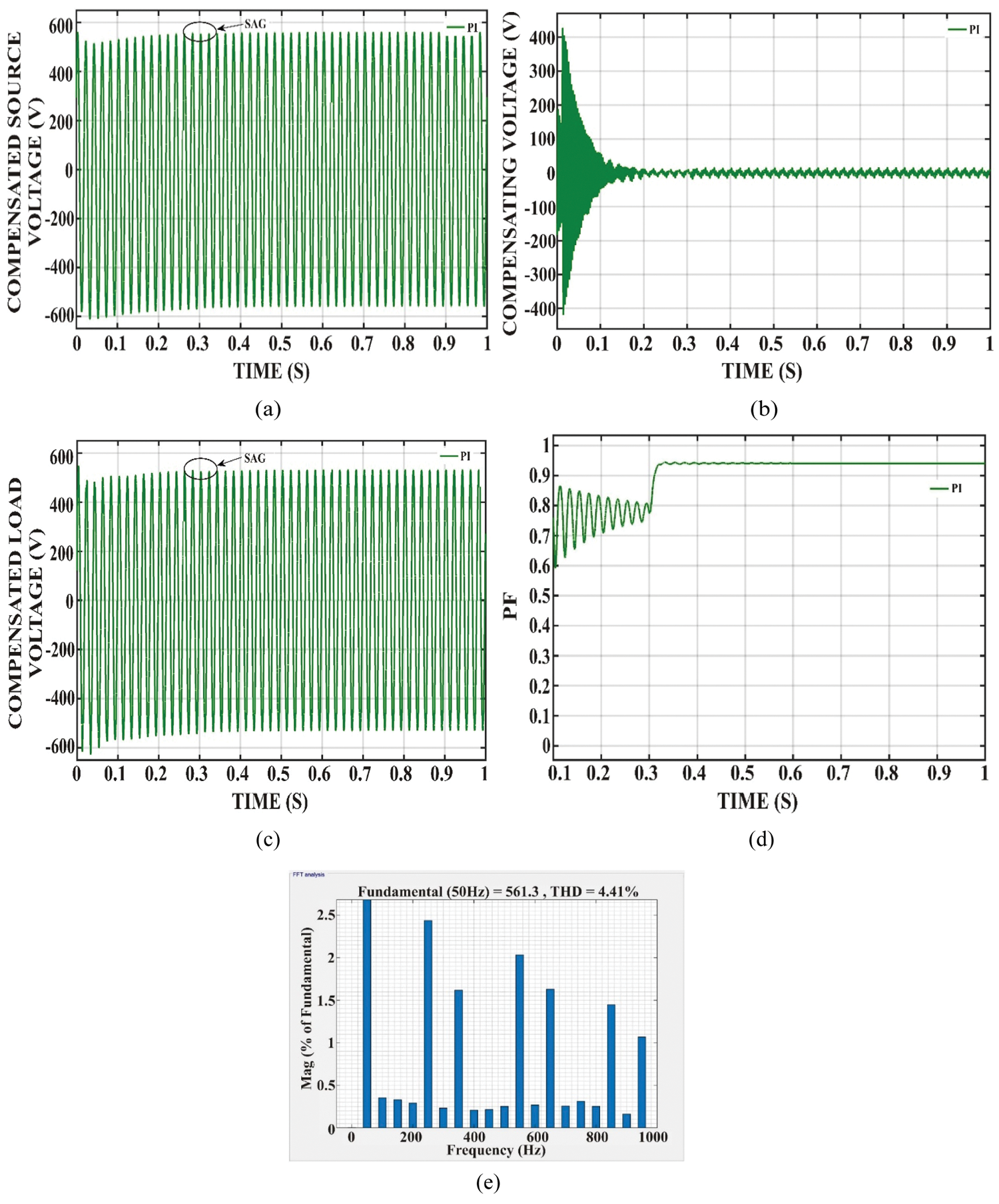
Figure 9: Performance of power system with conventional inverter based UPQC under sag (a) compensated source voltage (b) compensating voltage (c) compensated load voltage (d) power factor (e) THD
Performance of UPQC with cascaded H bridge five level-inverter is shown in Fig. 10. From Fig. 10, it is noted that 3.5 V is dropped during sag condition; THD is reduced to 1.35%, which is very less compared to a conventional system. Restoration time of voltage sag is 0.06 s by UPQC using CHB 5 level Inverter. The power factor by this system is improved to 0.94, while it is 0.935 by conventional UPQC. Performance of UPQC with Modified Reduced Switch MLI is shown in Fig. 11.
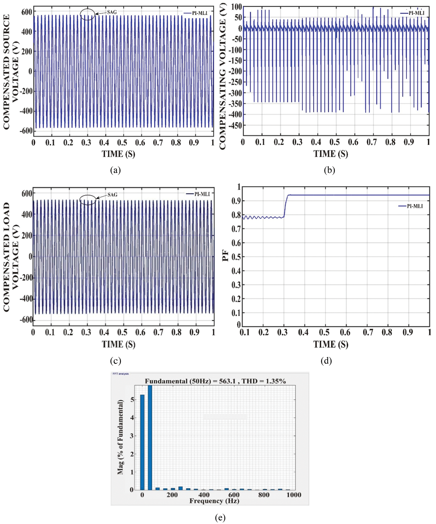
Figure 10: Performance of power system with cascaded H bridge 5 level inverter based UPQC under sag (a) compensated source voltage (b) compensating voltage (c) compensated load voltage (d) power factor (e) THD
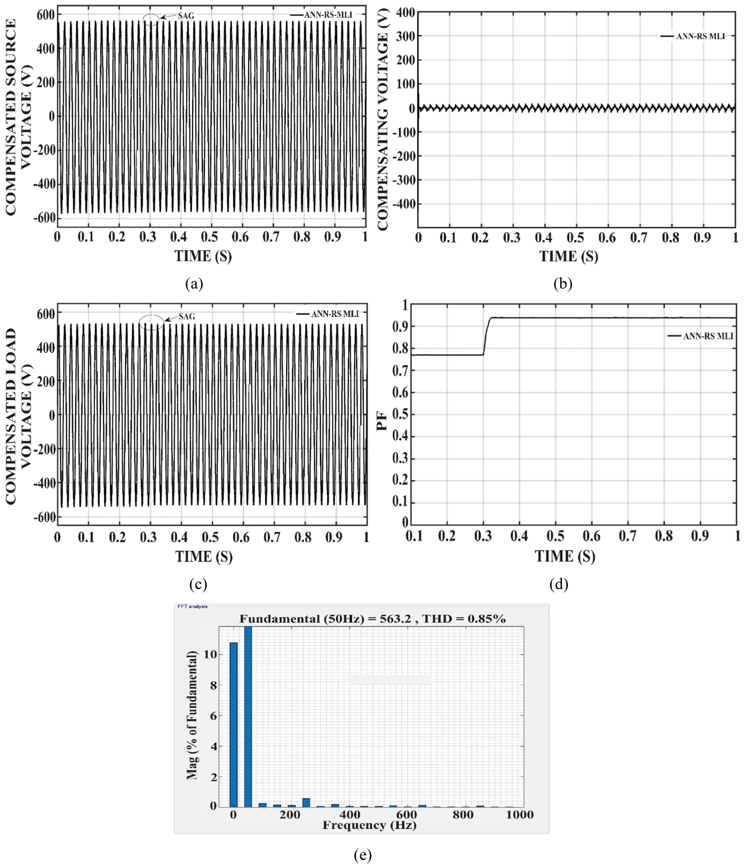
Figure 11: Performance of power system with modified reduced switch inverter based UPQC under sag (a) compensated source voltage (b) compensating voltage (c) compensated load voltage (d) power factor (e) THD
From Fig. 11, it is noted that 2.6 V is dropped during sag condition THD is reduced to 0.85%, which is very less compared to a conventional system. Restoration time under sag by the proposed system is 0.03 s, which is also very less compared to other topologies. The power factor of the system is 0.941 with the aid of this UPQC.
Performance of all analysed UPQC strategies in the aspect of voltage regulation is presented in Tab. 1.
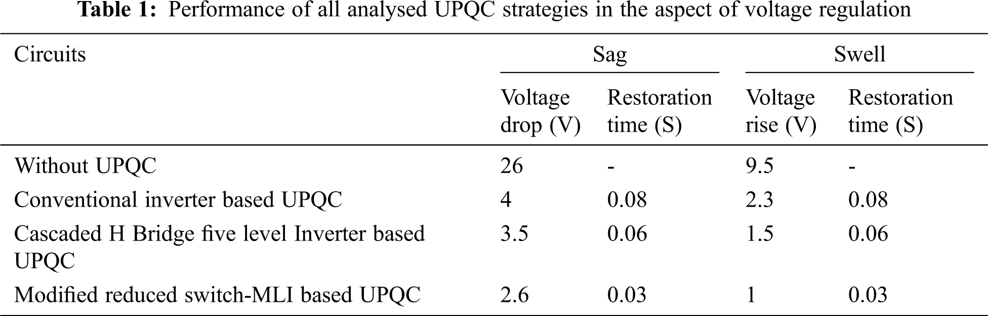
From Tab. 1, it is clear that during swell condition voltage rise is 9.5 V without UPQC, which is controlled to 2.3, 1.5, and 1 V by UPQC, five-level UPQC, and proposed configuration respectively. The restoration time of the proposed topology is 0.03 s which is very less compared to the other two configurations. Tab. 2 shows the performance of all analysed UPQC strategies in the aspect of THD and power factor.
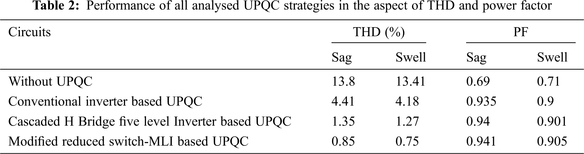
From Tab. 2, it is revealed that during swell condition THD is 13.41% without UPQC, which is controlled to 4.18%, 1.27%, and 0.75% by UPQC, five-level UPQC, and proposed configuration respectively. From Tabs. 1 and 2, it is noted that all topologies offered improved power factor compared to uncontrolled system. It is observed that under both sag and swell conditions voltage fluctuation, restoration time, and THD are reduced by cascaded MLI and ANN-based proposed approach compared to conventional UPQC.
From the analysis it is observed proposed configuration results improved power factor compared to all other configurations, under both sag and swell conditions. Voltage fluctuation by proposed configuration during sag, is reduced around 35% compared to conventional UPQC, while it is reduced around 57% under swell condition. Under sag condition, 80.72% of THD is reduced by proposed reduced switch MLI based UPQC compared to conventional UPQC, while reduction in THD under swell condition is 82.06%. Restoration time under both sag and swell conditions are reduced around 63% with the help of proposed UPQC method compared to conventional UPQC. Hence the analysis validates that, the proposed system offers improved performance compared to all other topologies under both sag and swell conditions in various power quality parameters such as power factor, voltage quality and harmonic mitigation.
In this paper, various topologies of UPQC using PI and ANN controllers are analysed for power quality enhancement in the distribution network. The three topologies are conventional UPQC, UPQC using cascaded H bridge five level inverter, and UPQC using modified reduced switch multilevel inverter with ANN control. Conventional UPQC and UPQC using cascaded H bridge inverter are controlled using a PI controller. All configurations are analysed under variable nonlinear load, which creates sag/swell. The power quality performance of each configuration is analysed under sag and swell conditions in the aspects of voltage compensation, restoration time for compensation, total harmonic distortion, and power factor. Compared to the uncompensated system, conventional UPQC reduces voltage fluctuation and power factor effectively, while THD is reduced to 4.41%. UPQC using cascaded H bridge Inverter offers improved performance of THD along with the voltage quality, but oscillation in power factor at the time of starting has to be reduced. Proposed topology offered to improve voltage compensation with minimum restoration time. THD of the proposed configuration is less than 1%, which is very less compared to other topologies. Under sag condition, 80.72% of THD is reduced by proposed reduced switch MLI based UPQC compared to conventional UPQC, while reduction in THD by cascaded H bridge five level inverter based UPQC is 69.4%. Similarly, under swell condition, THD reduction by cascaded H bridge and proposed configuration are 69.6% and 82.06% compared to conventional UPQC. This analysis validates that under both sag and swell conditions, proposed configuration offered reduced THD compared to all other methods. Meantime the power factor by the proposed system is high without any oscillation reveals the enriched performance of ANN. Hence it is validated from the analysis that the proposed system offers enhanced performance in all aspects with reduced switches. In future, this analysis may extend with various forms of MLI with minimum switches for UPQC.
Acknowledgement: The authors with a deep sense of gratitude would thank the supervisor for his guidance and constant support rendered during this research.
Funding Statement: The authors received no specific funding for this study.
Conflicts of Interest: The authors declare that they have no conflicts of interest to report regarding the present study.
1. M. Dhivya and A. J. Renoald, “Fuzzy grammar based hybrid split-capacitors and split inductors applied in positive output luo-converters,” International Journal of Scientific Research in Science, Engineering and Technology, vol. 3, pp. 327–332, 2017. [Google Scholar]
2. K. Santhiya, M. Devimuppudathi, D. S. Kumar and J. R. Albert, “Real time speed control of three phase induction motor by using lab view with fuzzy logic,” Journal on Science Engineering and Technology, vol. 5, no. 2, pp. 21–27, 2018. [Google Scholar]
3. B. Singh, A. Chandra and K. A. Haddad, “Power quality: An introduction,” in Power Quality: Problems and Mitigation Techniques, 1st ed, vol. 1. John Wiley and Sons, West Sussex, UK: Wiley Publishers, pp. 1–11, 2014. [Google Scholar]
4. H. Akagi, E. H. Watanabe and M. Aredes, “The instantaneous power theory,” in Instantaneous Power Theory and Applications to Power Conditioning, 2nd ed, vol. 1. John Wiley and Sons, Canada: Wiley-IEEE Press, pp. 37–111, 2017. [Google Scholar]
5. A. Bhattacharya, C. Chakraborty and S. Bhattacharya, “Parallel-connected shunt hybrid active power filters operating at different switching frequencies for improved performance,” IEEE Transactions on Industrial Electronics, vol. 59, no. 11, pp. 4007–4019, 2012. [Google Scholar]
6. V. K. Remya, P. Parthiban and V. Ansal, “Dynamic voltage restorer (DVR)–a review,” Journal of Green Engineering, vol. 8, no. 8, pp. 519–572, 2018. [Google Scholar]
7. B. Singh and J. Solanki, “A comparison of control algorithms for DSTATCOM,” IEEE Transactions on Industrial Electronics, vol. 56, no. 7, pp. 2738–2745, 2009. [Google Scholar]
8. H. Wang, “A unified model for the analysis of FACTS devices in damping power system oscillations III, unified power flow controller,” IEEE Transactions on Power Delivery, vol. 15, no. 3, pp. 978–983, 2000. [Google Scholar]
9. A. Ghosh and G. Ledwich, “A unified power quality conditioner (UPQC) for simultaneous voltage and current compensation,” Electric Power Systems Research, vol. 59, no. 1, pp. 55–63, 2001. [Google Scholar]
10. M. A. A. Yahiya and M. A. R. Uzair, “Performance analysis of DVR, DSTATCOM and UPQC for improving the power quality with various control strategies,” in Proc. Power and Energy Systems: Towards Sustainable Energy, IEEE, Bengaluru, India, pp. 1–4, 2016. [Google Scholar]
11. R. A. Wanjari, V. B. Savakhande, M. A. Chewale, P. R. Sonawane and R. M. Khobragade, “A review on UPQC for power quality enhancement in distribution system,” in Proc. Int. Conf. on Current Trends Towards Converging Technologies, IEEE, Coimbatore, India, pp. 1–7, 2018. [Google Scholar]
12. A. Nagarajan, P. Sivachandran, M. V. Suganyadevi and P. Muthukumar, “A study of UPQC: Emerging mitigation techniques for the impact of recent power quality issues,” Circuit World, vol. 47, no. 1, pp. 11–21, 2020. [Google Scholar]
13. V. Khadkikar and A. Chandra, “UPQC-S: A novel concept of simultaneous voltage sag/swell and load reactive power compensations utilizing series inverter of UPQC,” IEEE Transactions on Power Electronics, vol. 26, no. 9, pp. 2414–2425, 2011. [Google Scholar]
14. C. Salim and M. T. Benchouia, “Unified power quality conditioner based on a three-level NPC inverter using fuzzy control techniques for all voltage disturbances compensation,” Frontiers in Energy, vol. 8, pp. 221–239, 2014. [Google Scholar]
15. V. Muneer and A. Bhattacharya, “Cascaded H bridge multi-level inverter based unified power quality conditioner,” in Proc. Power India Int. Conf., IEEE, Kurukshetra, India, pp. 1–6, 2018. [Google Scholar]
16. C. Salim, “Power quality enhancement with UPQC systems based on multi-level (NPC) inverters,” in Proc. Electrical Engineering and Control Applications, Constantine, Algeria, pp. 45–59, 2018. [Google Scholar]
17. Y. Dhote and B. Khambra, “Neutral point clamped multi level inverter based unified power quality conditioner,” Journal for Research, vol. 6, no. 8, pp. 1–7, 2020. [Google Scholar]
18. A. K. Koshti and M. N. Rao, “A brief review on multilevel inverter topologies,” in Proc. Int. Conf. on Data Management, Analytics and Innovation, IEEE, Pune, India, pp. 187–193, 2017. [Google Scholar]
19. R. Pawar, S. P. Gawande, S. G. Kadwane, M. A. Waghmare and R. N. Nagpure, “Five-level diode clamped multilevel inverter (DCMLI) based electric spring for smart grid applications,” Energy Procedia, vol. 117, pp. 862–869, 2017. [Google Scholar]
20. K. Thenmalar, J. R. Albert, D. M. Begam and P. Madhumathi, “Power quality improvement in modular multilevel inverter using for different multicarrier PWM,” European Journal of Electrical Engineering and Computer Science, vol. 5, no. 2, pp. 19–27, 2021. [Google Scholar]
21. J. R. Albert and A. A. Stonier, “Design and development of symmetrical super-lift DC–AC converter using firefly algorithm for solar-photovoltaic applications,” IET Circuits Devices & Systems, vol. 14, no. 3, pp. 261–269, 2020. [Google Scholar]
22. J. Ebrahimi, E. Babaei and G. B. Gharehpetian, “A new multilevel converter topology with reduced number of power electronic components,” IEEE Transactions on Industrial Electronics, vol. 59, no. 2, pp. 655–667, 2012. [Google Scholar]
23. D. S. Vanaja, J. R. Albert and A. A. Stonier, “An experimental investigation on solar PV fed modular STATCOM in WECS using intelligent controller,” International Transactions on Electrical Energy Systems, vol. 31, no. 5, pp. e12845, 2021. [Google Scholar]
24. S. Srinath, M. P. Selvan and K. Vinothkumar, “Comparative evaluation of performance of different control strategies on UPQC connected distribution system,” in Proc. Int. Conf. on Innovative Computing and Information, IEEE, Mangalore, India, pp. 502–507, 2010. [Google Scholar]
25. V. Khadkikar, “Enhancing electric power quality using UPQC: A comprehensive overview,” IEEE Transactions on Power Electronics, vol. 27, no. 5, pp. 2284–2297, 2012. [Google Scholar]
26. A. J. Renoald, V. Hemalatha, R. Punitha, M. Sasikala and M. Sasikala, “Solar roadways-the future rebuilding infrastructure and economy,” International Journal of Electrical and Electronics Research, vol. 4, no. 2, pp. 14–19, 2016. [Google Scholar]
27. J. Wilamowski, M. Bogdan and J. D. Irwin, “Intelligent systems,” in Industrial Electronics Handbook, 2nd ed, vol. 1. Taylor and Francis Group, Boca Raton: CRC press, pp. 12–333, 2018. [Google Scholar]
 | This work is licensed under a Creative Commons Attribution 4.0 International License, which permits unrestricted use, distribution, and reproduction in any medium, provided the original work is properly cited. |