DOI:10.32604/iasc.2022.023252
| Intelligent Automation & Soft Computing DOI:10.32604/iasc.2022.023252 | |
| Article |
Forward Flight Performance Analysis of Supercritical Airfoil in Helicopter Main Rotor
1Visvesvaraya Technological University, Belagavi, Karnataka, 590018, India
2ACS College of Engineering, Bengaluru, Karnataka, 560074, India
*Corresponding Author: Inamul Hasan. Email: inamulhasan@acsce.edu.in
Received: 01 September 2021; Accepted: 09 November 2021
Abstract: In this research, the aerodynamic performance and flow characteristics of NASA SC (2)-0714 airfoil and HH02 airfoil in the helicopter main rotor are evidently analyzed. The supercritical airfoil is used in the aircraft for attaining better transonic and high-speed flow characteristics. Moreover, a specialized helicopter airfoil called HH02 is used in the Apache helicopter rotor for increasing the operational speed. As most of the high-speed helicopters are using four-bladed main rotor configuration, it is analyzed with prior attention. The lift and thrust act in different directions for the forward phase of the flight whereas the lift and thrust act in the same direction for the other phases of flight, which is analyzed in this work. The computational analysis is done by using ANSYS Fluent whereas the rotational analysis is done by using the Multiple Reference Frame (MRF) method. An analysis is carried out for different RPM of 400,600 and 800 with the combination of 0.3, 0.4 and 0.5 Mach numbers with the assistance of grid independence test. The result shows that the NASA SC (2)-0714 rotor increases the thrust of the rotor around 5% to 10% under various rotor and forward speeds. Thus, the results proves that the supercritical airfoil is highly capable of producing higher thrust and good aerodynamic characteristics.
Keywords: Helicopter rotor; supercritical airfoil; CFD; MRF; HH02 airfoil
The Helicopter has more advantages than the fixed-wing aircrafts. The flight phases of Helicopter are listed as vertical takeoff, hover, forward flight, sideward flight, and vertical descend. The helicopter requires no special place for the take-off and landing because almost all the terrains are suitable for the helicopter. In contrast to the Helicopter, the Aircraft needs a special runway for its takeoff and landing. In aircraft, the lift is produced by the wings and the thrust is produced by the engine but in the Helicopter, both the lift and thrust are produced by a rotor, which is driven by the engine. The engine is connected to the rotor through the shaft [1,2]. The helicopter is highly applicable for various purposes like fire rescue or agriculture as it has the hovering phase. Hovering is a special phase, in which a helicopter stands in the same position and altitude for a long time to serve a special operation.
The supercritical airfoil is a specialized airfoil, which is used in the aircraft for delaying the onset of shock and for increasing the critical Mach number [3]. The supercritical airfoils has good characteristics in the transonic region and acceptable flow characteristics in the low-speed region [4]. The speed of the aircraft or helicopter gets increased when the critical Mach number is increased [5]. The transonic region is delayed by the supercritical airfoil in the helicopter blades [6].
In this research, different combination of supercritical airfoil in the helicopter rotor blades is used to delay the onset of shock wave and to increase the Critical Mach number. The Helicopters have complex aerodynamic features like advancing and retreating sides of blades during rotation [7]. In the advancing side, the leading edge faces the flow direction whereas in the retreating side, the trailing edge faces the flow direction [8]. The flow characteristics and the lift get disturbed by the changes in advancing and retreating side [9]. The flow characteristics are represented in Fig. 1.
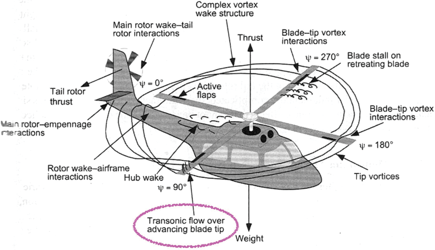
Figure 1: Flow characteristics of rotor blade
The speed of the Helicopter is limited because of having complex structure and aero-dynamical design [10]. The speed is limited by the circumstances like formation of shock at the tip of the rotor blade, behavior of flow in the retreating side, change of velocity from root to tip, fuselage wing interaction and main rotor- tail rotor interaction, [11]. The flow velocity is changed from the root to tip. The velocity at the blade tip is higher than the velocity at the root, which causes the formation of the transonic region at some parts of the flow. For increasing the speed of the helicopter, the design aspect like structural, engine and aero-dynamical characteristics have to be given importance [12]. This research focuses on the study of aerodynamic characteristics of helicopter blades using NASA SC (2)-0714 and HH02 airfoils.
The shape of the airfoil is the first parameter for the efficient aerodynamic design as it plays a major role in deciding the lift and drag [13,14]. Various airfoils are currently used in the applications like aircraft, helicopters, wind turbines and propeller blades design. However, some specialized airfoils are used for the wind turbine applications [15] or helicopter blades. The HH02 is a Hughes helicopter airfoil, which is specifically used in the Apache helicopters for obtaining good performance in rotor blades [13]. The supercritical airfoils are specially used in the supersonic aircraft to cross the sonic barrier [6]. Various researches are carried out to increase the aerodynamic efficiency as it helps in enhancing the payload and decreasing the fuel usage [13]. This research mainly deals with the calculation of thrust, which is produced by two different rotors with different airfoils. By evaluating the produced thrust and flow characteristics, the performance of the rotor is analyzed.
In recent days, the Computational Fluid Dynamics (CFD) techniques play an important role in all the areas of technological advancements [16,17]. In this research, the software like CFD tools, ANSYS R19.2 and Fluent are used for flow analysis [18]. The isolated blades are selected to reduce the complexity of the structure in the analysis [10,16]. The high-speed helicopter called Apache helicopter is a four-bladed helicopter, which uses HH02 airfoil for its wings. In this research, the four-bladed configurations of HH02 and NASA SC (2)-0714 airfoil are compared. With the assistance of CFD techniques, the rotor blades are analyzed through the Moving or sliding mesh technique [19,20] and MRF techniques [17]. The MRF is preferred as it requires less computational space and less time. In addition, this MRF has both the rotation and non-rotation parts. The rotating parts are in a rotating frame whereas the non-rotating parts are in the stationary frame. The rotating mesh is done for the rotating parts and a normal stationary mesh is done for the non-rotating parts [21]. The Blade element momentum theory (BEMT) and Blade element theory (BET) are applicable for the calculation of the theoretical performance of rotating propellers and helicopter blades [11,22].
The velocity is gradually varied from the root to tip. The velocity at the blade tip is higher than the velocity at the root, which causes a shock formation in the tip of the blade [23]. The speed of the Helicopter is limited because of having complex structure and aero-dynamical design. The speed of the Helicopter is limited due to is complex structure and aero-dynamical constraints. The proposed methodology of this work is explained in Fig. 2. The configurations of Helicopter blade vary from two to four. In this research, four bladed configurations are preferred because most of the high-speed helicopters are four-bladed. Though the four-bladed configuration increases the weight of the helicopter, it provides more stability and more aero-dynamical performance than the two or three-bladed helicopters [1].
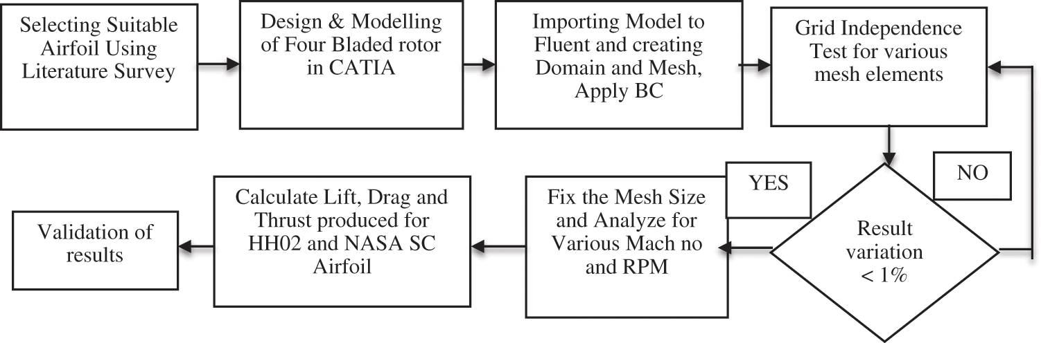
Figure 2: Methodology
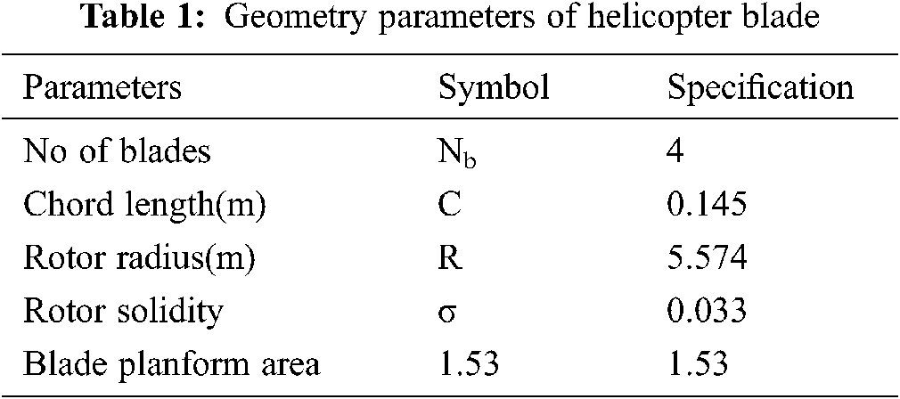
The airfoil coordinates are downloaded for both HH02 and NASA SC(2)-0714 airfoils [24]. These coordinates are imported to CATIA V5 software to design the blades [10]. The details of the geometry are presented in Tab. 1. The geometry Parameters are same for both the NASA SC(2)-0714 and HH02 rotors. The blade models are designed with the separate elements like Leading-edge, Trailing edge, Gap at the trailing edge and hub. The geometry modeling of seperate elements give a better option for getting acurate results of meshing [22]. The shape of the airfoil is shown in Fig. 3 and the CAD model of the geometry is shown in Fig. 4. The parts of Leading-edge and Trailing edge are created as shown in Fig. 5. The shape of the airfoil shows the change of trailing edge shape in HH02 and NASA SC(2)-0714 airfoil. The HH02 has the upward trailing edge bent and the NASA SC(2)-0714 has the downward bent.
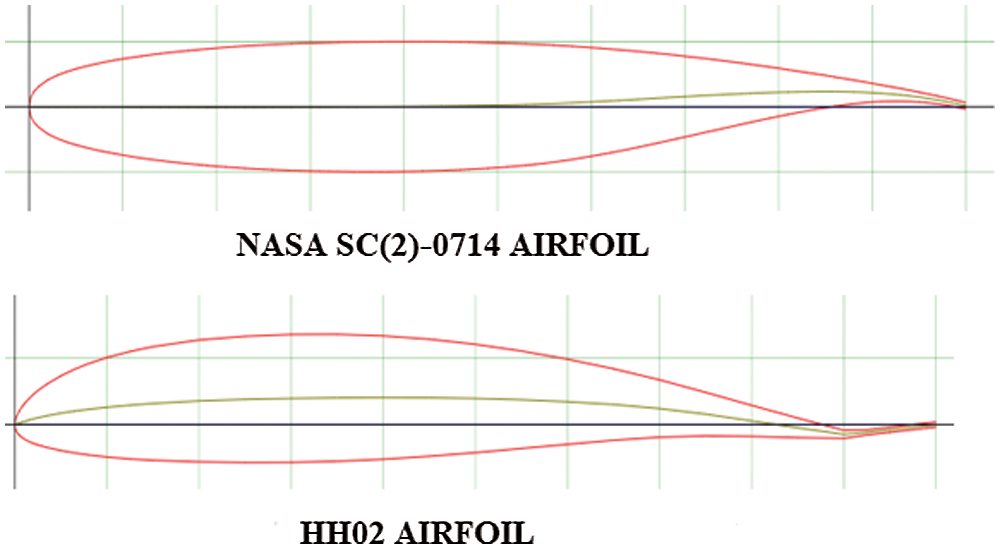
Figure 3: Airfoil shape

Figure 4: CAD model of rotor blade

Figure 5: Elements of wing rotor model
The formation of correct domain is important in the analysis process. The created domain has to be free from affecting the flow characteristics or model. For helicopter blade analysis in forward flight, the cylindrical domain provide a good correlation with the experimental results. The flow in the top is regarded as an inlet whereas the flow in the bottom is regarded as an outlet. Two domains are created, in which one is created near the blade and another one is created away from the blade. The rotational domain is created only for the blade sections and the non-rotating domain is created outside the blade for the flow conditions [23]. The created domains are big as it has no impact on the flow behavior of the model. The computational domain and flow conditions are represented in Figs. 6 and 7.

Figure 6: Domain creation

Figure 7: Flow condition in domain
2.3 Grid Generation and Solver Setting
The grid generation is regarded as an important process in CFD. The grid is generated by using the Fluent software, which is capable of doing fine mesh. The domain is finely meshed before the analysis to get an accurate result. The blades and the computational domain are meshed in a very finer way [25]. The meshing of the blade with domain is shown in Fig. 8 and the rotor is shown in Fig. 9. The inflation layers are created near the blade to capture the flow separation around the blade, to capture the flow and to avoid the slip in the flow [15]. The inflation layer is shown in Fig. 10. The meshing is done in the Leading-edge, trailing edge gap and trailing edge to accurately capture the flow. As most of the helicopter rotor analysis uses the unstructured mesh, the unstructured mesh is used in this complex body. The rotating mesh is created for the blades and Stationary mesh is created for the domain [26].

Figure 8: Meshed model with domain

Figure 9: Meshing of blades

Figure 10: Inflation layer around blades
The boundary conditions of inlet and outlet are applied in the solver conditions of fluent [17,27]. The mesh quality is maintained by keeping minimum orthogonal quality [28]. The solver is selected and Reynolds averaged Navier Stokes (RANS) turbulence model is used. Various models are used for analyzing the helicopter blades in MRF techniques [10,17].
The performance of each model is compared with the experiment results. For the analysis of turbulence model, the models like standard K-ε, Realizable k-ε, or k-ω SST are used. Among these models, the standard K-ε model is not so applicable for the curved surfaces and it shows much variation with experimental results. The realizable K-ε model is selected as it is highly applicable for the curved surfaces. It is used in many rotational analysis like helicopter rotor analysis and wind turbine blade analysis. The realizable k-ε model shows a good correlation with the experimental results [29]. The Y+ value is calculated and maintained as 30 to 50 for all the analysis as the realizable k-ε model is used for the analysis [15].
3 Verification & Validation of Results
The grid Independence test is an important process in CFD analysis [15,29]. The grid Independence test has been conducted for various grid sizes. The created domain and the number of elements have to be free from affecting the flow characteristics and results. The grid Independence test is started for coarse mesh. The mesh size is decreased and the number of elements is increased to get a fine mesh. Finally, the finer mesh with 2486109 elements is fixed, in which the lift and thrust coefficient are not changed much than the previous mesh. The obtained results of Lift and thrust values of various mesh sizes are compared. The mesh is made finer until the result variation of the analysis become less than 1% [15]. The grid independence test is shown in Tab. 2. The grid Independence Test curve is shown in Fig. 11.

Figure 11: Grid independence test

The obtained results of CFD have to be validated with the previous research results or experimental results [30,31]. In this research, the results are validated with the previous research results of helicopter rotors analysis. The results of Cp vs. X/C curve is compared with the obtained results of previous experimental results from the papers of Supercritical Airfoil [3–5] and HH02 airfoils [32–34]. The results of Cl vs. Cd also compared with the previous results, which proves that the values are almost same [2]. In addition, the results are compared with the Cp vs. X/C curve, which is obtained in the X-foil software. The Cp vs. X/C curve for HH02 rotor in [33] is compared with the obtained curve of CFD results, which is shown in Fig. 12. Similarly, the results of Supercritical rotor Cp vs. X/C curve is compared with the obtained results [35], which is shown in Fig. 13.
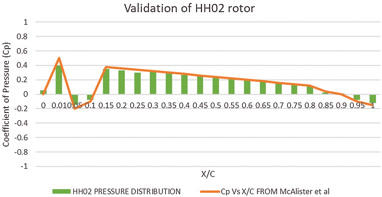
Figure 12: Validation of HH02 rotor

Figure 13: Validation of supercritical rotor
The NASA SC (2)-0714 and HH02 models are analyzed for different RPMs and different Mach numbers. Normally, the Mach number of helicopter is 0.3 to 0.4. Hence, the analysis is done for the Mach numbers of 0.3, 0.4, and 0.5. Generally, the RPM of helicopter rotors is 500 to 600 RPM. Hence, the analysis is carried out for the RPM of 400, 600, and 800 RPM. A combination of all the values of Mach number with various values of RPM is analyzed and the aerodynamic characteristics results are recorded. The thrust values are calculated because the thrust and lift values are almost in the same direction. The thrust values of both HH02 and NASA SC (2)-0714 rotor are recorded and the values are compared. The result shows that the NASA SC (2)-0714 rotor has more thrust than the HH02 rotor. The value of thrust varies for each speed and RPM of NASA SC (2)-0714 than HH02. The detailed result of Mach number and speed is discussed below.
Figs. 14–22 represent the pressure contour and velocity vector contour for the combination of all Mach numbers and RPM. The results clearly show the pressure contour over the blade and the variation of pressure over the blade. It also shows maximum and minimum pressure over the blade section. The pressure gets increased when the RPM and forward speed of the helicopter is increased. The pressure is minimum at 400 rpm and maximum at 800 rpm for all the forward speeds. When comparing the Pressure between HH02 and NASA SC (2)-0714 rotors, it clearly proven that the pressure difference of NASA SC (2)-0714 is higher for all the forward and rotational speeds.

Figure 14: (a) Pressure contour for M = 0.3 and 400 rpm (b) velocity vector contour for M = 0.3 and 400 rpm

Figure 15: (a) Pressure contour for M = 0.3 and 600 rpm (b) velocity vector contour for M = 0.3 and 600 rpm

Figure 16: (a) Pressure contour for M = 0.3 and 800 rpm (b) velocity vector contour for M = 0.3 and 800 rpm
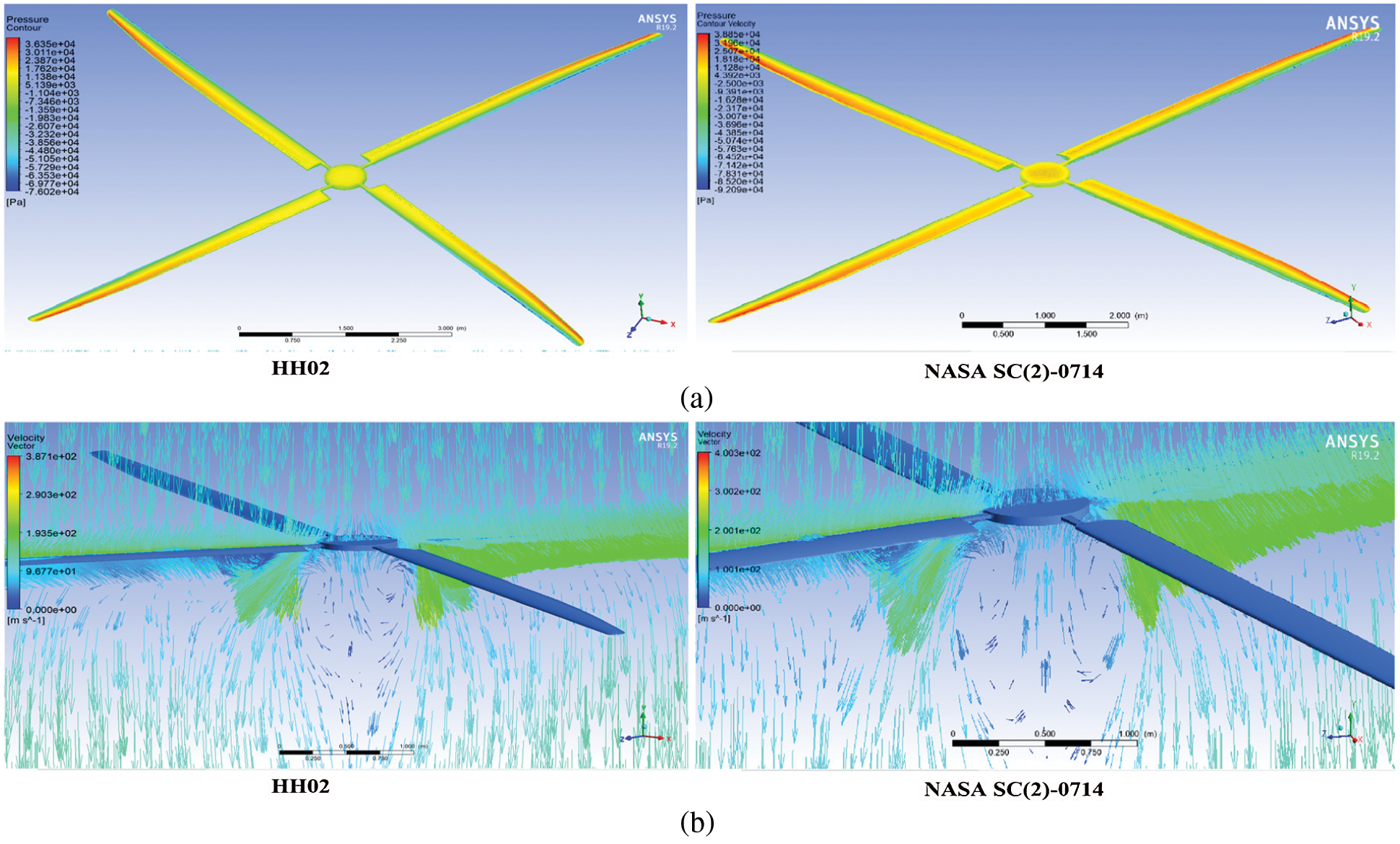
Figure 17: (a) Pressure contour for M = 0.4 and 400 rpm (b) velocity vector contour for M = 0.4 and 400 rpm

Figure 18: (a) Pressure contour for M = 0.4 and 600 rpm (b) velocity vector contour for M = 0.4 and 600 rpm

Figure 19: (a) Pressure contour for M = 0.4 and 800 rpm (b) velocity vector contour for M = 0.4 and 800 rpm

Figure 20: (a) Pressure contour for M = 0.5 and 400 rpm (b) velocity vector contour for M = 0.5 and 400 rpm

Figure 21: (a) Pressure contour for M = 0.5 and 600 rpm (b) velocity vector contour for M = 0.5 and 600 rpm

Figure 22: (a) Pressure contour for M = 0.5 and 800 rpm (b) velocity vector contour for M = 0.5 and 800 rpm
Similarly, the velocity vector contour represents the elements like velocity magnitude, variation of velocity, the direction of velocity over the blade and around the blade. The velocity is maximum for 800 rpm with 0.5 Mach no and 1003 m/s forward speed whereas it is minimum at 400 rpm with 0.3 Mach no and 355.3 m/s forward speed. The features like maximum pressure, minimum pressure and maximum velocity over the blade are represented in Tabs. 3 & 4.

The pressure difference is one of the important factors in finding the aerodynamic characteristics of the airfoil. The pressure difference between the upper and lower surfaces of blades plays a significant role in the lift of rotor blades. From Tabs. 3 & 4, it is observed that the pressure difference of N ASA SC (2)-0714 is higher than the HH02 rotor. Hence, the aerodynamic characteristic of the NASA SC (2)-0714 rotor is better than the HH02 rotor in the same inlet condition. The maximum velocity variables are represented in Tabs. 3 & 4. In accordance with the basic lift formula, the lift is directly proportional to the square of the velocity. As the velocity in NASA SC (2)-0714 rotor is high, the lift is also high, which is comparatively better than the HH02 rotor.
In Tab. 5, the improvement of thrust is listed for both NASA SC(2)-0714 and HH02 rotors in terms of percentage. It is clear that the NASA SC(2)-0714 rotor is generating more thrust than the HH02 rotor. In addition, the NASA SC(2)-0714 rotor produces high thrust around 5% to 10% than HH02 rotor. It is thus clear that, the NASA SC(2)-0714 rotor delivers better performance for various RPM and forward speeds. The maximum thrust percentage of 9.98% is attained for M = 0.4 and 800 RPM whereas the minimum thrust percentage of 5.07% is attained for M = 0.4 and 400 rpm.


Fig. 23 shows the variation of thrust vs. RPM for all Mach numbers and rotational speeds. The produced thrust is higher for all Mach numbers and all rotational speeds. It shows the variation of thrust for NASA SC(2)-0714 rotor and HH02 rotor. Fig. 24 shows the variation of Velocity under various RPM for NASA SC(2)-0714 and HH02 rotors. The lift is directly proportional to the square of velocity. Thus, the lift and aerodynamic characteristics of NASA SC(2)-0714 are better than the HH02 rotor. Fig. 25 Shows the pressure difference for various RPM. The pressure difference on the upper and lower part of the airfoil has to be high for having maximum lift. From the graph, it is clear that the NASA SC(2)-0714 rotor is having more pressure difference than the HH02 rotor. Thus, the NASA SC(2)-0714 rotor has better performance than the HH02 rotor.

Figure 23: Thrust vs. RPM
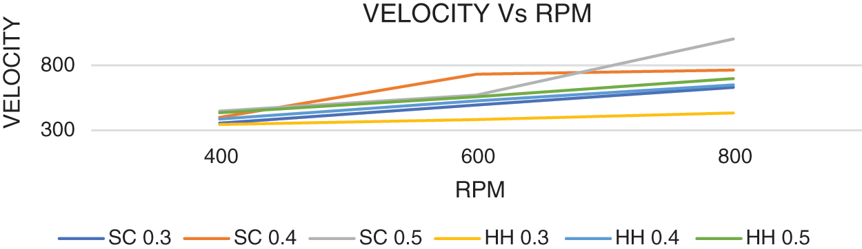
Figure 24: Velocity vs. RPM

Figure 25: Pressure difference vs. RPM
The analysis results of various forward and rotational speeds show that the NASA SC (2)-0714 rotor exhibit more thrust than the HH02 rotor. The rotor thrust is increased about 5% to 10% for various forward and rotational speeds. The pressure difference of NASA SC (2)-0714 rotor is also higher than the HH02 rotor. The results of computational analysis show that the supercritical airfoil is capably replaced in the helicopter main rotor blades and it provides better efficiency for various speeds. The produced thrust of supercritical airfoil is higher than the HH02 airfoils. The increased aerodynamic efficiency aids in achieving better loading capability, maneuvering and fuel efficiency. It is highly possible to replace the heavy and high strength materials. The flow characteristic analysis can be analyzed for various phases like Hovering, Axial climb and axial descent states to understand the flow characteristics. An analysis is carried out for one main rotor and a tail rotor configurations. The Coaxial or Tandem rotor configuration can be analyzed to find the flow characteristics of the supercritical airfoil in other helicopter configurations.
Funding Statement: The authors received no specific funding for this study.
Conflicts of Interest: The authors declare that they have no conflicts of interest to report regarding the present study.
References:
1. R. V. Petrescu, R. Aversa, B. Akash, J. Corchado, F. Berto et al., “About helicopters,” Journal of Aircraft and Spacecraft Technology, vol. 1, no. 3, pp. 204–223, 2017. [Google Scholar]
2. D. Cvetkovic, I. Kostic, C. Mitrovic, A. Bengin and D. Radakovic, “Mathematical models of helicopter flight dynamics,” in 40th AIAA Aerospace Sciences Meeting & Exhibit, Reno, NV, USA, pp. 529–537, 2002. [Google Scholar]
3. T. Zhao, Y. Zhang, H. Chen, Y. Chen and M. Zhang, “Supercritical wing design based on airfoil optimization and 2.75 D transformation,” Aerospace Science and Technology, vol. 56, pp. 168–182, 2016. [Google Scholar]
4. W. Niu, Y. Zhang, C. Haixin and M. Zhang, “Numerical study of a supercritical airfoil/wing with variable-camber technology,” Chinese Journal of Aeronautics, vol. 33, no. 7, pp. 1850–1866, 2020. [Google Scholar]
5. C. D. Harris, “NASA supercritical airfoils: A matrix of family-related airfoils,” National Aeronuatics and Space Administration Scientific and Technical Information Division, vol. 2969, pp. 1–72, 1990. [Google Scholar]
6. H. Sobieczky and A. R. Seebass, “Supercritical airfoil and wing design,” Annual Review of Fluid Mechanics, vol. 16, no. 1, pp. 337–363, 1984. [Google Scholar]
7. I. V. Abalakin, V. G. Bobkov, T. K. Kozubskaya, V. A. Vershkov, B. S. Kritsky et al., “Numerical simulation of flow around rigid rotor in forward flight,” Fluid Dynamics, vol. 55, no. 4, pp. 534–544, 2020. [Google Scholar]
8. D. Han, K. Yang and G. N. Barakos, “Extendable chord for improved helicopter rotor performance,” Aerospace Science and Technology, vol. 80, pp. 445–451, 2018. [Google Scholar]
9. J. R. Majhi and R. Ganguli, “Modeling helicopter rotor blade flapping motion considering nonlinear aerodynamics,” Computer Modeling in Engineering and Sciences, vol. 27, no. 1/2, pp. 25–36, 2008. [Google Scholar]
10. K. M. Pandey, U. Kumar, G. Kumar, D. Deka, D. Das et al., “CFD analysis of an isolated main helicopter rotor for a hovering flight at varying RPM,” in ASME International Mechanical Engineering Congress and Exposition, vol. 45172, pp. 543–551, 2012. [Google Scholar]
11. D. Han, V. Pastrikakis and G. N. Barakos, “Helicopter performance improvement by variable rotor speed and variable blade twist,” Aerospace Science and Technology, vol. 54, pp. 164–173, 2016. [Google Scholar]
12. A. Brocklehurst and G. N. Barakos, “A review of helicopter rotor blade tip shapes,” Progress in Aerospace Sciences, vol. 56, pp. 35–74, 2013. [Google Scholar]
13. R. Mukesh, K. Lingadurai and U. Selvakumar, “Airfoil shape optimization based on surrogate model,” Journal of the Institution of Engineers (IndiaSeries C, vol. 99, no. 1, pp. 1–8, 2018. [Google Scholar]
14. R. Mukesh, K. Lingadurai and U. Selvakumar, “Application of nontraditional optimization techniques for airfoil shape optimization,” Modelling and Simulation in Engineering, vol. 2012, pp. 1–6, 2012. [Google Scholar]
15. A. Dilimulati, T. Stathopoulos and M. Paraschivoiu, “Wind turbine designs for urban applications: A case study of shrouded diffuser casing for turbines,” Journal of Wind Engineering and Industrial Aerodynamics, vol. 175, pp. 179–192, 2018. [Google Scholar]
16. I. Hasan and R. Mukesh, “Aerodynamic analysis of isolated 3 bladed helicopter with supercritical airfoil,” Solid State Technology, vol. 63, no. 6, pp. 3663–3682, 2020. [Google Scholar]
17. T. Wan, “Aerodynamic analysis of helicopter rotor blades in heavy rain condition,” in 51st AIAA Aerospace Sciences Meeting Including the New Horizons Forum and Aerospace Exposition, Texas, USA, pp. 653–664, 2013. [Google Scholar]
18. R. Steijl, G. Barakos and K. Badcock, “A framework for CFD analysis of helicopter rotors in hover and forward flight,” International Journal for Numerical Methods in Fluids, vol. 51, no. 8, pp. 819–847, 2006. [Google Scholar]
19. C. Zhou and M. Chen, “Computational fluid dynamics trimming of helicopter rotor in forward flight,” Advances in Mechanical Engineering, vol. 12, no. 5, pp. 1–13, 2020. [Google Scholar]
20. M. Biava, W. Khier and L. Vigevano, “CFD prediction of air flow past a full helicopter configuration,” Aerospace Science and Technology, vol. 19, no. 1, pp. 3–18, 2012. [Google Scholar]
21. P. A. Silva, P. Tsoutsanis and A. F. Antoniadis, “Simple multiple reference frame for high-order solution of hovering rotors with and without ground effect,” Aerospace Science and Technology, vol. 111, pp. 106418, 2021. [Google Scholar]
22. Y. Kang, M. Liu, S. Kao-Walter, J. Liu and Q. Cen, “Numerical analysis of pressure distribution in a brush seal based on a 2-D staggered tube banks model,” Intelligent Automation and Soft Computing, vol. 25, no. 2, pp. 405–411, 2019. [Google Scholar]
23. N. A. Vladimirova, “CFD analysis and calculation of aerodynamic characteristics of helicopter rotor,” in 39th European Rotorcraft Forum, Moscow, Russia, pp. 24–37, 2013. [Google Scholar]
24. Site, UIUC Airfoil Data. “Airfoil database.” UIUC Applied Aerodynamics Group https://m-selig.ae.illinois.edu/ads/coord_database.html. [Google Scholar]
25. M. Elfarra, M. Kaya and F. Kadioglu, “A parametric CFD study for the effect of spanwise parabolic chord distribution on the thrust of an untwisted helicopter rotor blade,” in AIAA Aerospace Sciences Meeting, pp. 1795–1804, 2018. [Google Scholar]
26. A. Seeni, “Aerodynamic performance characterization and structural analysis of slotted propeller: part A effect of position,” INCAS Bulletin, vol. 12, no. 2, pp. 183–198, 2020. [Google Scholar]
27. Y. Noorollahi, M. J. Ziabakhsh, M. Rezaei and M. Tahani, “Analysis of turbulent flow on tidal stream turbine by RANS and BEM,” Computer Modeling in Engineering & Sciences, vol. 127, no. 2, pp. 515–532, 2021. [Google Scholar]
28. M. Didwania and K. K. Khatri, “Analysis of stalling over FLAPED wing of an aeroplane by CFD code,” IOSR Journal of Mechanical and Civil Engineering, vol. 16, no. 4, pp. 45–54, 2019. [Google Scholar]
29. M. H. Mohamed, A. M. Ali and A. Hafiz, “A CFD analysis for H-rotor darrieus turbine as a low speed wind energy converter,” Engineering Science and Technology, an International Journal, vol. 18, no. 1, pp. 1–13, 2015. [Google Scholar]
30. D. Pelletier, “Verification, validation, and uncertainty in computational fluids dynamics,” Canadian Journal of Civil Engineering, vol. 37, no. 7, pp. 1003–1013, 2010. [Google Scholar]
31. L. I. Garipova, A. S. Batrakov, A. N. Kusyumov, S. A. Mikhaylov and G. Barakos, “Aerodynamic and acoustic analysis of helicopter main rotor blade tips in hover,” International Journal of Numerical Methods for Heat & Fluid Flow, vol. 26, no. 7, pp. 2101–2118, 2016. [Google Scholar]
32. W. J. McCroskey, K. W. McAlister, L. W. Carr and S. L. Pucci, “An experimental study of dynamic stall on advanced airfoil sections. volume 1. summary of the experiment,” NASA Technical Momerandum 84245, USA, pp. 1–103, 1982. [Google Scholar]
33. K. W. McAlister, S. L. Pucci, W. J. McCroskey and L. W. Carr, “An experimental study of dynamic stall on advanced airfoil sections. volume 2. Pressure and force data,” NASA Technical Momerandum 84245, USA, pp. 1–647, 1982. [Google Scholar]
34. H. Yeo, “Assessment of active controls for rotor performance enhancement,” Journal of the American Helicopter Society, vol. 53,. no. 2, pp. 152–163, 2008. [Google Scholar]
35. L. I. Runze, D. Kaiwen, Y. Zhang and C. Haixin, “Pressure distribution guided supercritical wing optimization,” Chinese Journal of Aeronautics, vol. 31, no. 9, pp. 1842–1854, 2018. [Google Scholar]
 | This work is licensed under a Creative Commons Attribution 4.0 International License, which permits unrestricted use, distribution, and reproduction in any medium, provided the original work is properly cited. |