DOI:10.32604/iasc.2022.021834
| Intelligent Automation & Soft Computing DOI:10.32604/iasc.2022.021834 | |
| Article |
Hybrid Microgrid based on PID Controller with the Modified Particle Swarm Optimization
1Sivaji College of Engineering and Technology, Anna University, Chennai, 600025, India
2Ponjesly College of Engineering, Anna University, Chennai, 600025, India
*Corresponding Author: R. K. Rojin. Email: rkrojin123@gmail.com
Received: 16 July 2021; Accepted: 30 August 2021
Abstract: Microgrids (MG) are distribution networks encompassing distributed energy sources. As it obtains the power from these resources, few problems such as instability along with Steady-State (SS) issues are noticed. To address the stability issues, that arise due to disturbances of low magnitude. Small-Signals Stability (SSS) becomes mandatory in the network. Convergence at local optimum is one of the major issues noticed with the existing optimization algorithms. This paper proposes a detailed model of SSS in Direct Current (DC)-Alternate Current (AC) Hybrid MG (HMG) using Proportional Integral and Derivative Controller (PIDC) tuned with Modified Particle Swarm Optimization (MPSO) algorithm to alleviate such issues. The power is extracted from Renewable Energy Resources (RER), such as Photovoltaic (PV), Micro-Hydro (MH), and Wind Energy Conversation System (WECS). For tracking the power more efficiently, Maximum Power Point Tracking (MPPT) techniques are employed. Boost Converters (BC) are used and inverters are employed to convert DC to the AC. Here, the power flow is managed by the PIDC. If the Firing Angle (FA) is not properly determined, it results in instability and steady-state stability issues. To address this, the optimum tuning parameters are chosen for PIDC, by utilizing the MPSO. Finally, through experimentation analysis, the proposed system’s performance is analyzed and compared with the existing algorithms and validated.
Keywords: Modified particle swarm optimization (MPSO); proportional integral and derivative (PID) controller; maximum power point tracking (MPPT); boost converter; renewable energy resources
MG is the constituent of smart grid technologies, and it can ameliorate the Power System’s (PS) economics, resilience, security, reliability, along with sustainability [1]. The MG demand is augmented on account of the MG’s benefits [2]. An MG is typically split into three categories: AC-MG, DC-MG, and hybrid AC/DC-MG can familiarize as a small-PS, that facilitates the larger-scale RER’s integration along with the application [3]. HMG has more advantages, better power-sharing, enhanced system dynamics, and optimum management than the other MG’s [4]. Recently, RES have been extensively adopted in electric grids [5]. More integration of RES is encouraged by the beneficial traits of the MG conception. In addition, ancillary services concerning frequency support together with voltage regulation could well be potentially commenced by MG [6]. Wind Generation (WG), Fuel Cells (FC), PV, micro-turbines, and hydropower turbines are the main RER that demands hybrid AC/DC-MG, and generates intermittent output power [7,8].
Though RES has countless advantages, the MG under RES suffers from dynamic performance issues along with stability [9]. The stability issues can well be mostly split into the SSS and the larger disturbance stability, as per the disturbance nature [10]. In a MG, the SSS [11] is associated with the feedback controller, increased load switching, along with the power limit of micro-sources. A fault with a succeeding island poses greater disturbance stability issues. Amongst the assortment of stability issues, encompassing poor SSS [12] will be a concern for attaining the dependable function of the MG. In addition, SS stability issues are as well found in the HMG. The stability issue is labelled as the instability that relies on DG units intended for sufficient balancing of energy [13]. The control system adopted finds the solution for instability issues [14].
In the MG, two sorts of control strategies were employed. The second control approach applies a completely decentralized method signifying locally controlled units [15]. Numerous control techniques as Proportional-Integral (PI) controller [16], PIDC [17], as well as a fuzzy logic controller [18], are proposed in various literatures. If the controllers are not fed with the optimum parameters, instability issues remain, hence as a result, the optimal selection is required. Nevertheless, many techniques encounter slower convergence speed together with erroneous outcomes [19]. Lately, nature-inspired algorithms are turning out to be an attractive solution for minimizing or maximizing non-differentiable non-linear function, say Genetic Algorithm (GA) [20] Particle Swarms Optimization (PSO) [21], however, undergo premature convergence.
Shahsavari et al. [22] rendered a mathematical strategy for examining the high infiltration effects induced by the PV power plant on the SSS of a power network and for ameliorating the probabilistic SSS of the PS, utilizing the optimal Fractional Order (FO) PIDC. In this strategy, a Non-dominated Sorting GA (NSGA-II) type multi-objective optimization approach was employed for ascertaining the FO-PID stabilizer-centric parameters on the basis of two performance indices, such as Integral Square Error (ISE) and Integral Absolute Error (IAE).
Ray et al. [23] recommended frequency control in MG consisting of wind, diesel engine generators, PV, and fuel cell accompanied by the energy storage (ES), as battery ES and flywheel ES. A firefly-integrated particle swarm (FF-PSO) centric hybridized optimization structure was utilized for tuning parameters, and the PIDC was utilized for lessening the frequency deviation in the MG structure under diverse operating scenarios, like the variations in load demand and wind speed (WS).
Abdulkhader et al. [24] examined some impacts of Renewable Energy (RE) System-centered MG penetration on the control and dynamic stability of an effective multi-area multi-machine structure under diverse operating scenarios. The model of a type-2 fuzzy FOPID-centric PS stabilizer (PSS), by introducing a meta-heuristic hybridized algorithm for enhancing the stability.
Nezhadpashaki et al. [25] built a dynamic strategy for Inverter Based Distribution Generation units (IBDG), loads, and network branches. This strategy scrutinized some impacts of SSS constraint on optimum location, accompanied by the IBDG’s size in a radial distribution framework. GA was utilized to ascertain the IBDG’s optimal size and optimal location for reduing the total active power loss. Propounded an adaptive fuzzy proportional-integral controller [26] for ameliorating the dynamic performance, rendered by the inverter interfaced autonomous MG. The propounded model had the controller dynamics, network dynamics, load dynamics, and dynamics of a filter. Renuka et al. [27] developed PSO methodology, a multi-stage optimization approach, for ameliorating the SSS and energy penetration. The work had two stages: initially, the PSO was employed for maximizing RE penetration to the test structures. Secondly, the system’s SSS was ameliorated with maximal RE penetration.
Santhoshkumar et al. [28] recommended the transient along with SSS enhancement in MG, employing Whale Optimization Algorithms (WOA) together with Ant Lion Optimization (AWOALO) and virtual Synchronous Generators (SG). AWOALO was executed to regulate optimally the parameters, thus ensure a smooth transition, subsequent to an alteration or disturbance. Yi Zhang et al. [29] established an adaptive coordinated control approach aimed at the networked AC/DC MG, for ameliorating the system’s frequency along with DC voltage stability. Initially, the converter strategy was designed, based on the synchronverter and virtual DC machine. Further, to ameliorate the system stability’s performance, the parameter model of the Adaptive Virtual Inertia (AVI) together with virtual Governor-Gain (GG) was employed consequently. To address the stability issues that arise due to disturbances of low magnitude Small-Signals Stability (SSS) becomes mandatory. Convergence at local optimum is one of the major issues noticed with the existing optimization algorithms. This paper proposes a detailed model of SSS in Direct Current-Alternate Current Hybrid MG using Proportional Integral and Derivative Controller tuned with Modified Particle Swarm Optimization (MPSO) algorithm to alleviate such issues.
3 Enhancement of Small Signal Stability in DC-AC Hybrid Microgrid Based On PID Controller with MPSO Algorithm
Currently, MG has undergone quick development, as it is proved to be an effectual solution for the dependable hybridization of Distributed Generations (DG) units, energy storage systems, along with loads, that functions in grid-connected or islanded mode. Here, the HMG has the competency to be joined directly to the major power grid. In the hybrid grid, the power is supplied to the Dynamic Load (DL) or static load. Most researches analyze the stability in static loads, intended for an MG. DL considerably influences the MG’s stability on account of its voltage along with frequency-dependent nature. Thus, a smaller variation in voltage together with frequency can make a considerable effect on the MG’s stability with the existence of DL. In the proposed work, the power is produced as the combination of RES, say, PV, WECS, along with MH, which is supplied to the DL in the HMG. BC is used for a grid-linked HMG, the current being managed by FA control. Further, the PIDC is employed for controlling the FA to avoid the stability issues. To overcome the stability issue and to enhance SSS, MPSO is employed for optimizing the parameters and is aimed at designing the perfect controller that renders the better outcome. The block diagram is of the proposed system is given in Fig. 1.

Figure 1: Block diagram for the proposed methodology
3.1 Renewable Energy Resources
Initially, the combination of RER, say PV, MH, and WECS, is employed for producing power. In RES, the MPPT is employed to achieve maximum power extraction in the entire conditions. In addition, when the load is higher, analogized to the particular threshold, the remaining power is stored on the battery.
Utilizing PV modules, the solar energy is changed to electricity. The solar cells can be joined in parallel or series, relying on the preferred voltage as well as current [30]. The output current power (
wherein,
Wherein,
Wherein,
The power that is produced, as of a MH power plant relies on the head’s size along with hydro discharge [31]. MH potential energy (
Wherein,
Hydro-potential aimed at electrical energy can be attained, as of a lower hydro-flow. The energy generated is kinetic and given, as per the subsequent equation:
Wherein,
Therefore, the electrical power produced by the MH plant (
Wherein,
The power output as of the wind counts on the WS, which is computed based on the power-law equation, as rendered in the subsequent equation:
Wherein,
Wherein,
Wherein,
Subsequent to power gain, as one of the complete resource, the battery stack is employed to store the energy, as the produced power is more compared to the load demand. As the generation can’t fulfil the load needs, the battery power will be extracted. Relying on the charging along with discharging state, the current may be negative or positive.
In which
Wherein,

Figure 2: DC-AC HMG structure
Fig. 2 shows the proposed DC-AC HMG’s design. The power is transported to the main grid, utilizing the converters. MH, WECS, and the AC loads are connected to the AC bus; the battery, PV along with DC loads is connected to the DC bus.
3.2 Converters and Their Controllers
The attained power as of RER is fed to the MG, utilizing the BC with PIDC. The BC is utilized in the proposed technique. The current is managed by FA. Thus, FA is a significant measure. If it exceeds the particular angle, SSS issue and the SS stability issue are raised in the converter. Therefore, the FA is ought to be controlled, by utilizing the PIDC. In PIDC, the input parameter is chosen by means of the MPSO, and discussed in the sections below.
PID controller: In PIDC, the proportional gain output is large, as the errors are larger. In the case of Integral, the error will be added continuously, as well as multiply with a constant. The derivative path’s output signal is rendered by means of the Rates of Change (ROC) of error. The output is less, as the ROC of error is low, and larger as the ROC of error is high. PIDC will eradicate the forced oscillations along with SS error. The controller’s output is mathematically written as,
Wherein,
Wherein,
Wherein,
Wherein,
Wherein,

Figure 3: Pseudo code for the proposed MPSO
The velocity together with position updation of the particle is evinced as:
Wherein,
Fig. 3 displays the MPSO pseudo-code, that presents the initialization, mutation, the procedure of computing distance between the starting and the other particles, along with the velocity, as well as position updation steps.
This section presents the proposed SSS enhancement system and its performance. For the purpose of simulation, MATLAB/SIMULINK platform is utilized. Fig. 4 shows the simulation model of the proposed SSS enhancement system,
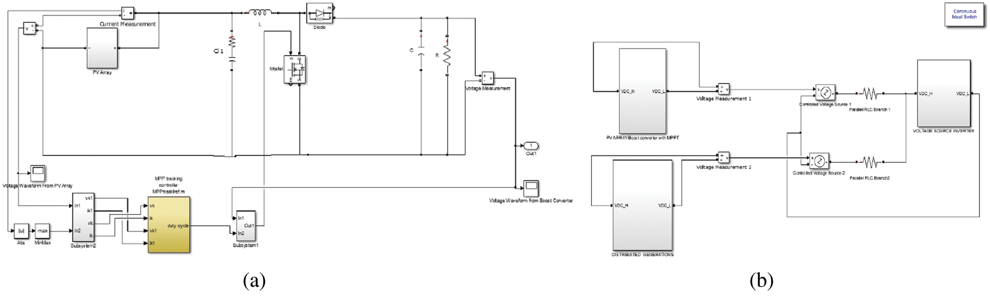
Figure 4: Matlab simulation of (a) PV array with MPPT and BC, and (b) Hybrid MG
Fig. 4 shows the Simulink output of (a) the PVA with MPPT and BC and (b) the hybrid MG design. In Fig. 4a, the BC is employed for realizing the MPPT operation and acquiring the DC voltage output. By effectuating MPPT, the working voltage shifts closest to the utmost extreme power under different weather conditions, and thereby ameliorates the hybrid PS’s efficiency. The MPPT creates the control signal, which feeds the BC. The BC endeavors to elevate the output voltage level. This BC converts DC to AC current. Fig. 4b elucidates the voltage source inverter in detail. The voltage sources as of the distributed generator and the PVA BC with MPPT is strictly regulated by voltage source controllers.
Here, the proposed work is examined based on the performance, in respect of obtained current and voltage waveforms. The analyses could be explicated further using the below figures.
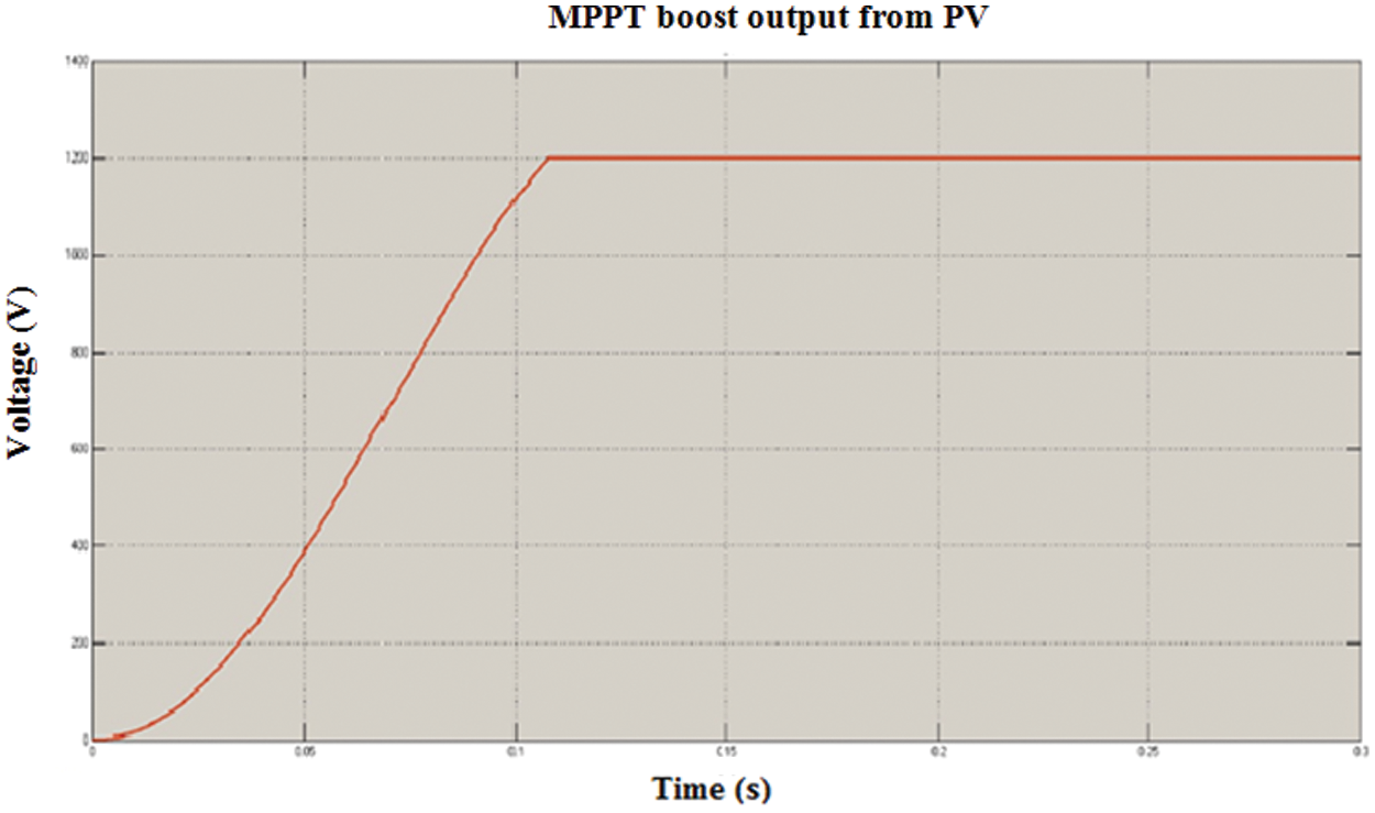
Figure 5: Output analysis of MPPT boost from PV array
Fig. 5 shows the output of the PVA with a BC utilizing incremental conductance MPPT. The output voltage is analyzed in respect of time in seconds. MPPT boost provides 1200 V output voltage in 0.12 s time, 400 V in 0.05 s, and, 1130 V in 0.1 s. For the remaining time duration (i.e., 0.15 s, 0.2 s, 0.25 s, and 0.3), 1200 V output is gained as of the MPPT boost. After 0.12 s, the maximal voltage is acquired. On this account, it elucidates that, the acquired voltage level is 1200 V for the MPPT BC, as of PVA.
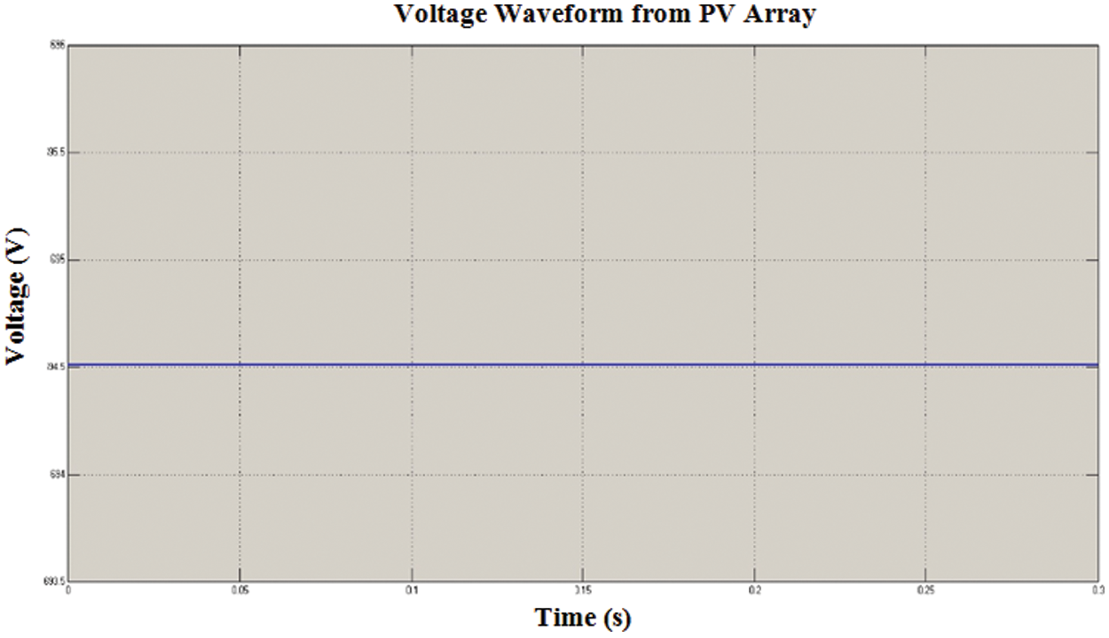
Figure 6: Analysis of voltage waveform from PV array
Fig. 6 shows the voltage waveform as of the PVA. The analysis is made by means of varying the time between the generation and voltage. This analysis shows that a constant voltage of 694.5 V in entire time variation is noticed.
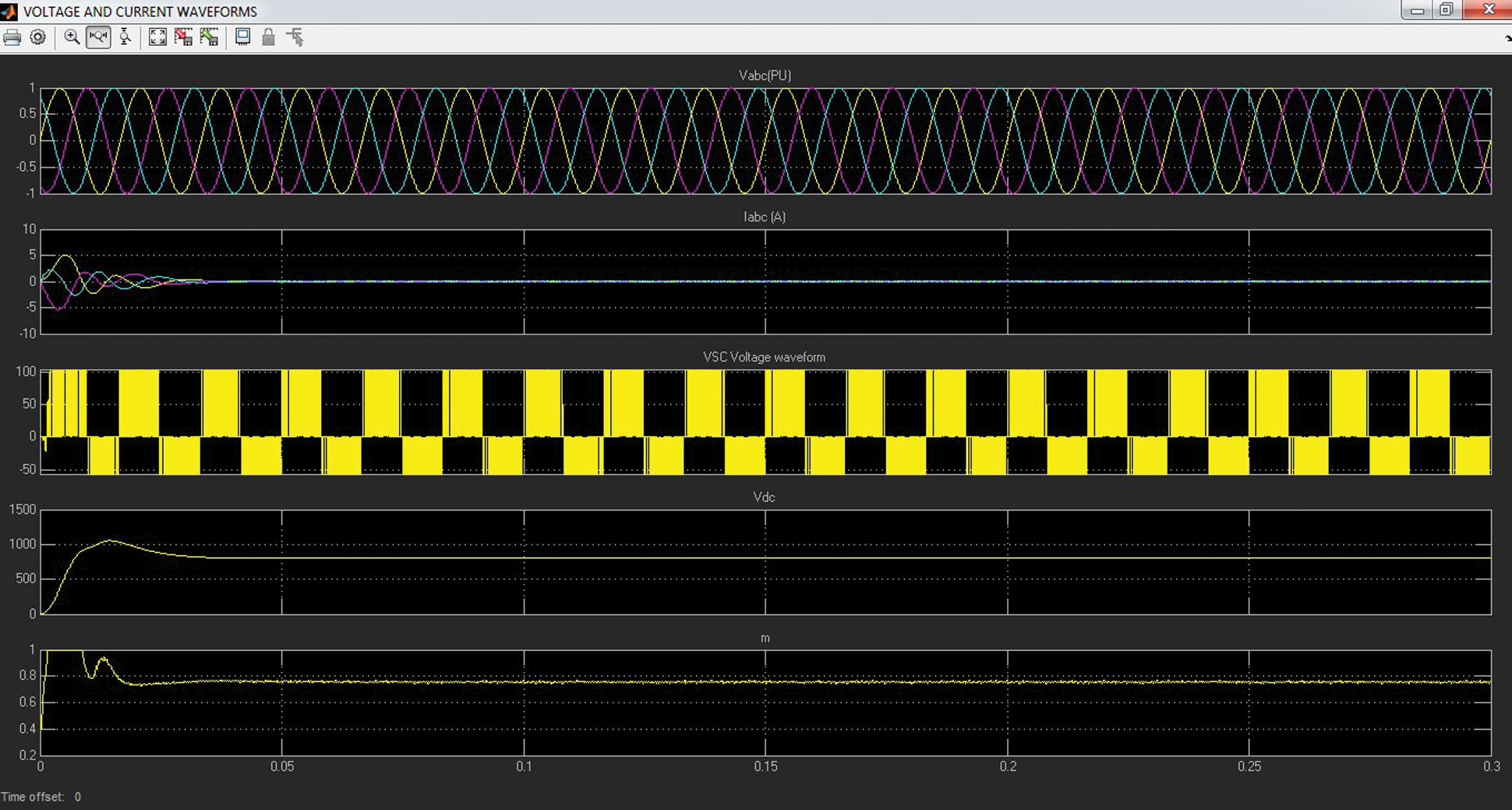
Figure 7: Simulated result of voltage and current waveforms
Fig. 7 shows the simulated outcomes of the voltage as well as current waveform of the implemented work. In 0.02 s, the current waveform varies as of −1 Kw to 1 Kw as shown in the top, followed by –5 Kw to 5 Kw in the second. Next, the third, fourth, and fifth simulated outcomes show the voltage waveforms. In between the time intervals, the voltage ventures into the negative value for the first three time-interval and it has a positive value for the other three time-interval.
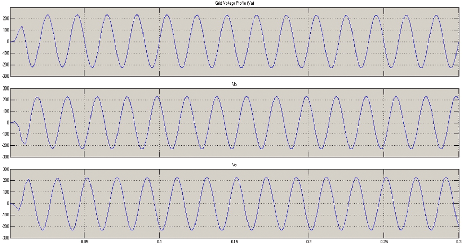
Figure 8: Distribution grid voltage profile
Fig. 8 shows the distribution grid voltage profile. Here, the voltage varies between –200 V to 200 V. The simulated outcomes of the distribution grid voltage profile are analyzed based on time in seconds. Here, the attained voltage is the same as of 0.05 s to 0.3 s.
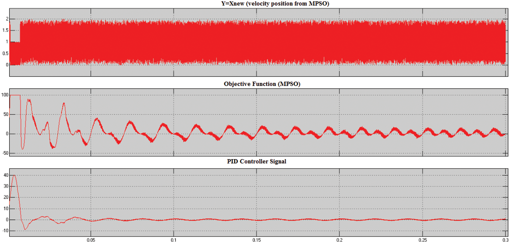
Figure 9: Simulated result of reference signals for gate pulse generation
Fig. 9 displays the simulated graph of the reference signal (RS) for gate pulse generation. The RS is utilized for testing the system capability. Here, the PIDC signal, the optimal parameter selection regarding an objective function in MPSO, and the signal acquired after velocity updation utilizing MPSO are shown. Subsequent to updating, the signal has an excellent result, and the performance is given.
The Proposed MPSO is compared to the existing PSO [21], FF-PSO [23], DGA-BFA [24], and GA [20] based on fitness performance. This comparison have been performed for different iterations. Tab. 1 shows the fitness values attained by different algorithms,
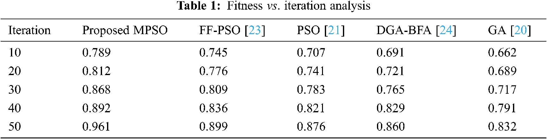
Tab. 1 shows the FF attained by the proposed MPSO algorithm and the existing FF-PSO, PSO, DGA-BFA, and GA algorithm, in respect of iterations (10 to 50). For 50 iterations, the MPSO algorithm attained 0.961- FF, whereas, the existing PSO has 0.876, existing FF-PSO has 0.899, DGA-BFA has 0.860 and the existing GA has 0.832 FF. Moreover, the proposed MPSO acquires the highest FF whilst the existing GA achieves the lower-most FF. FF-PSO, PSO, DGA-BFA is much better as compared to GA. Likewise, for the remaining iterations, the proposed method has better fitness results than the existing ones. From this analysis, the proposed work based optimal parameter selection is confirmed to achieve a better result, as confirmed to the existing algorithms. The graphical explanation of fitness vs. iteration analysis is plotted in Fig. 10,
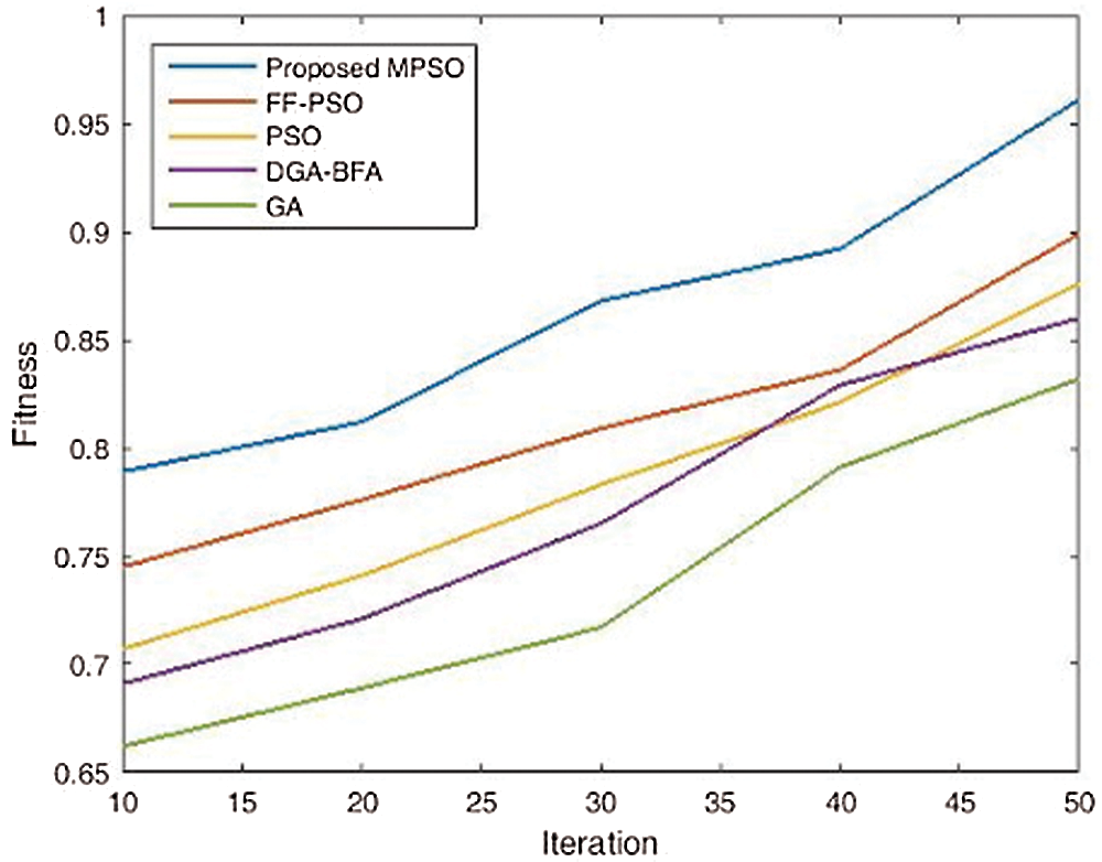
Figure 10: Graphical representation of fitness vs. iteration analysis
As SSS has an imperative role in ensuring the proper functioning of an MG system, SSS enhancement is requisite. The instability issues may arise, on account of the unsuitable parameters in the controller, which might affect the SSS. PIDC with the MPSO algorithm in DC-AC hybrid MG is proposed in this research for enhancing the SSS. Initially, the power is derived from the combination of RER. Here, excessive power is stored in a battery. Next, the converters and their controllers are explicated. Amid the experimentation investigation, the performance shown by means of the proposed system is analyzed based on the current and voltage waveforms, where better current and voltage are obtained with proposed one. Also, the RS for the pulse generation is analyzed. Then, the MPSO is compared to the existing PSO, FF-PSO, DGA-BFA, and GA, in respect of their fitness values. The MPSO acquired the higher most fitness value. Henceforth, the proposed work is perceived to attain SSS enhancement. In the future, the proposed work can well be extended by utilizing advanced controller approaches, and more RER are joined to acquire high power.
Acknowledgement: The author with a deep sense of gratitude would thank the supervisor for his guidance and constant support rendered during this research.
Funding Statement: The authors received no specific funding for this study.
Conflicts of Interest: The authors declare that they have no conflicts of interest to report regarding the present study.
1. Z. Li and M. Shahidehpour, “Small-signal modeling and stability analysis of hybrid ac/dc microgrids,” IEEE Transactions on Smart Grid, vol. 10, no. 2, pp. 1–11, 2018. [Google Scholar]
2. A. Ali, W. Li, R. Hussain, X. He, B. W. Williams et al., “Overview of current microgrid policies, incentives and barriers in the European Union, United States and China,” Sustainability, vol. 9, no. 7, pp. 1146, 2017. [Google Scholar]
3. Y. Zhang, Q. Sun, J. Zhou, L. Li, W. Panfeng et al., “Coordinated control of networked AC/DC microgrids with adaptive virtual inertia and governor-gain for stability enhancement,” IEEE Transactions on Energy Conversion, vol. 36, no. 1, pp. 1–11, 2020. [Google Scholar]
4. D. K. Dheer, S. Doolla and A. K. Rathore, “Small signal modeling and stability analysis of a droop based hybrid AC/DC microgrid,” in Proc. IES, Florence, Italy, IEEE, pp. 3775–3780, 2016. [Google Scholar]
5. B. Xie, Y. Liu, Y. Ji and J. Wang, “Two-stage battery energy storage system (BESS) in AC microgrids with balanced state-of-charge and guaranteed small-signal stability,” Energies, vol. 11, no. 2, pp. 322, 2018. [Google Scholar]
6. A. U. Krismanto, N. Mithulananthan and A. Lomi, “Dynamic droop control in microgrid for stability enhancement considering RES variation,” in Proc. ISGT, Europe, pp. 1–6, 2017. [Google Scholar]
7. S. Parhizi, H. Lotfi, A. Khodaei and S. Bahramirad, “State of the art in research on microgrids: A review,” IEEE Access, vol. 3, pp. 890–925, 2015. [Google Scholar]
8. H. R. Baghaee, M. Mirsalim, G. B. Gharehpetian and H. A. Talebi, “A decentralized power management and sliding mode control strategy for hybrid AC/DC microgrids including renewable energy resources,” IEEE Transactions on Industrial Informatics, vol. 3, pp. 1–11, 2017. [Google Scholar]
9. Y. Yan, D. Shi, D. Bian, B. Huang, Z. Yi et al., “Small-signal stability analysis and performance evaluation of microgrids under distributed control,” IEEE Transactions on Smart Grid, vol. 10, no. 5, pp. 4848–4858, 2019. [Google Scholar]
10. R. Majumder, “Some aspects of stability in microgrids,” IEEE Transactions on Power Systems, vol. 28, no. 3, pp. 3243–3252, 2013. [Google Scholar]
11. B. Wen, D. Boroyevich, R. Burgos, P. Mattavelli and Z. Shen, “Small-signal stability analysis of three-phase AC systems in the presence of constant power loads based on measured d-q frame impedance,” IEEE Transactions on Power Electronics, vol. 30, no. 10, pp. 5952–5963, 2015. [Google Scholar]
12. A. Aderibole, H. H. Zeineldin, M. S. E. Moursi, J. C. H. Peng and M. A. Hosani, “Domain of stability characterization for hybrid microgrids considering different power sharing condition.0s,” IEEE Transactions on Energy Conversion, vol. 33, no. 1, pp. 312–323, 2018. [Google Scholar]
13. F. S. Rahman, T. Kerdphol, M. Watanabe and Y. Mitani, “Active power allocation of virtual synchronous generator using particle swarm optimization approach,” Energy and Power Engineering, vol. 09, no. 04, pp. 414–424, 2017. [Google Scholar]
14. A. Karimi, Y. Khayat, M. Naderi, R. Mirzaee and H. B. Evrani, “Improving transient performance of VSG based microgrids by virtual FACTS functions,” in Proc. SGC, Tehran, Iran, 2018. [Google Scholar]
15. A. Khodadadi, P. H. Divshali, M. H. Nazari and S. H. Hosseinian, “Small-signal stability improvement of an islanded microgrid with electronically-interfaced distributed energy resources in the presence of parametric uncertainties,” Electric Power Systems Research, vol. 160, no. 9, pp. 151–162, 2018. [Google Scholar]
16. A. Mohanty, M. Viswavandya, D. Mishra, P. K. Ray, S. Patra et al., “An optimized STATCOM controller for voltage stability and reactive power compensation in an isolated microgrid,” in Proc. PCITC, Bhubaneswar, India, 2015. [Google Scholar]
17. H. Moussa, A. Shahin, J. P. Martin, S. Pierfederici and N. Moubayed, “Optimal angle droop for power sharing enhancement with stability improvement in islanded microgrids,” IEEE Transactions on Smart Grid, vol. 9, no. 5, pp. 5014–5026, 2018. [Google Scholar]
18. P. C. Sekhar, S. Mishra and R. Sharma, “Data analytics based neuro-fuzzy controller for diesel-photovoltaic hybrid AC microgrid,” IET Generation, Transmission & Distribution, vol. 9, no. 2, pp. 193–207, 2015. [Google Scholar]
19. P. Satapathy, S. Dhar and P. K. Dash, “Stability improvement of PV-BESS diesel generator-based microgrid with a new modified harmony search-based hybrid firefly algorithm,” IET Renewable Power Generation, vol. 11, no. 5, pp. 566–577, 2017. [Google Scholar]
20. M. Regad, M. Helaimi, R. Taleb, H. A. Gabbar and M. A. Othman, “Fractional order PID control of hybrid power system with renewable generation using genetic algorithm,” in Proc. SEGE, IEEE, pp. 139–144, 2019. [Google Scholar]
21. M. Regad, M. Helaimi, R. Taleb, A. M. Othman and H. A. Gabbar, “Frequency control in microgrid power system with renewable power generation using PID controller based on particle swarm optimization,” in Proc. ICAIRES, Cham, Springer, pp. 3–13, 2019. [Google Scholar]
22. H. Shahsavari and A. Nateghi, “Optimal design of probabilistically robust controller to improve small signal stability of PV integrated power system,” Journal of the Franklin Institute, vol. 356, no. 13, pp. 7183–7209, 2019. [Google Scholar]
23. P. K. Ray and A. Mohanty, “A robust firefly-swarm hybrid optimization for frequency control in wind/PV/FC based microgrid,” Applied Soft Computing, vol. 30, pp. 105823 (1–322019. [Google Scholar]
24. K. H. Abdulkhader, J. Jacob and A. Mathew, “Robust type-2 fuzzy fractional order PID controller for dynamic stability enhancement of power system having RES based microgrid penetration,” Int. Journal of Electrical Power & Energy Systems, vol. 110, pp. 357–371, 2019. [Google Scholar]
25. M. A. Nezhadpashaki, F. Karbalaei and S. Abbasi, “Optimal placement and sizing of distributed generation with small signal stability constraint,” Sustainable Energy, Grids and Networks, vol. 80, pp. 100380 (1–92020. [Google Scholar]
26. S. M. M. Tafreshi, H. A. Zamani and S. M. Hakimi, “Optimal sizing of distributed resources in microgrid with loss of power supply probability technology by using breeding particle swarm optimization,” Journal of Renewable and Sustainable Energy, vol. 3, no. 4, pp. 043105 (1–172011. [Google Scholar]
27. T. K. Renuka, P. Reji and S. Sreedharan, “An enhanced particle swarm optimization algorithm for improving the renewable energy penetration and small signal stability in power system,” Renewables: Wind, Water, and Solar, vol. 5, no. 1, pp. 156, 2018. [Google Scholar]
28. T. Santhoshkumar and V. Senthilkumar, “Transient and small signal stability improvement in microgrid using AWOALO with virtual synchronous generator control scheme,” ISA Transactions, vol. 104, pp. 56–60, 2020. [Google Scholar]
29. Y. Zhang, Q. Sun, J. Zhou, L. Li, W. Panfeng et al., “Coordinated control of networked AC/DC microgrids with adaptive virtual inertia and governor-gain for stability enhancement,” IEEE Transactions on Energy Conversion, vol. 36, no. 1, pp. 95–110, 2021. [Google Scholar]
30. S. Ferahtia, A. Djerioui, S. Zeghlache and A. Houari, “A hybrid power system based on fuel cell, photovoltaic source and super capacitor,” SN Applied Sciences, vol. 2, no. 5, pp. 1–11, 2020. [Google Scholar]
31. S. Ramadoni and I. Soesanti, “Planning of hybrid micro-hydro and solar photovoltaic systems for rural areas of central java,” Indonesia Journal of Electrical and Computer Engineering, vol. 2020, pp. 1–6, 2020. [Google Scholar]
 | This work is licensed under a Creative Commons Attribution 4.0 International License, which permits unrestricted use, distribution, and reproduction in any medium, provided the original work is properly cited. |