DOI:10.32604/iasc.2022.023083
| Intelligent Automation & Soft Computing DOI:10.32604/iasc.2022.023083 | |
| Article |
Improved Radio Resource Allocation in 5G Network Using Fuzzy Logic Systems
1Erode Sengunthar Engineering College, Erode, 638057, India
2Sona College of Technology, Salem, 636005, India
*Corresponding Author: S. Vimalnath. Email: s.vimal112@gmail.com
Received: 27 August 2021; Accepted: 11 October 2021
Abstract: With recent advancements in machine-to-machine (M2M), the demand for fastest communication is an utmost concern of the M2M technology. The advent of 5G telecommunication networks enables to bridge the demand on satisfying the Quality-of-Service (QoS) concerns in M2M communication. The massive number of devices in M2M communication is henceforth do not lie under limited resource allocation by embedding the 5G telecommunication network. In this paper, we address the above limitation of allocation the resource to prominent M2M devices using Adaptive Neuro Fuzzy Inference System (ANFIS). In ANFIS, the adoption of rules will imply the resource allocation with the devices of top priority and it reduces based on the priority. The ANFIS controller acts as a central controller that implies the resource allocation with its rules on the M2M devices. The simulation is performed to test the efficacy of fuzzy logic system on allocation 5G resources to M2M model. The results show that the ANFIS model achieves higher level of allocating the resources than other existing methods in terms of reduced network delay, increased throughput, packet delivery rate and energy efficiency.
Keywords: Fuzzy logic control; M2M; ANFIS; QoS; 5G; resource allocation
Every year, the amount of data traffic from a mobile device will increase due to the rapid adoption of mobile devices. In other words, the base station serves increased number of users, but there is a limit to the number of users the base station can serve because of the scarcity of radio resources. Offloading the data to the base station (BS) via M2M communications is a way to distribute traffic loads across multiple devices. If the M2M devices do not establish connection between them, the process of increasing the spectrum becomes significantly faster. In an ultra-dense network (UDNs), the segregation of the radio resource blocks is an essential issue that greatly influences the spectrum efficiency and system capacity. It is hence necessary for the model to analyse a block allocation problem in the context of M2M communications in the UDN 5G cellular system.
In the recent past, numerous studies [1–6] have been conducted on resource allocation for M2M, which can be categorised into various groups. While the cellular user equipment’s far exceeds the number of M2M users, this paper argues that the demand for location-based M2M services is significant (DUEs). In [1], the method used an area controller, and the resource allocation technique developed there could be utilised for uplink and downlink. To take these ideas one step further, approaches in [2–6] looked at how a base station can decide between M2M devices (say mobile device or IoT device) for a given user. Once it was discovered which of the several user modes a paper would occur under, the papers proposed resource allocation algorithms which considered the different considerations that went into allocating radio resources to a particular user.
The previous solutions only address the problem, where limited cellular users are greater than M2M users. As a result, resources are not employed effectively where the users are fewer than M2M users. Specifically, the preceding restriction states that a pair of M2M users can reuse a M2M radio resource block only when they both have M2M phones. It can be noted that, in general, even numbers, like [2,3], cannot have this limit, and none the less, the proposed methods have a temporal complexity that is quite high and so cannot be employed in ultra-dense environments. In this second route, the notion is introduced that the cellular subscribers are fewer than the M2M subscribers.
In [7], it is seen that the geographic users could not utilise the same resource block to mitigate the interference, and so this study is developed with machine learning model to distribute radio blocks to each user. The related works first allot resources for users and then, after considering M2M users [8–13], decide how those resource blocks should be reused. While we see that if we allocate resource blocks for the users first, several M2M devices fails in effectively reusing the radio resource in an UDN [14]. Also, it is essential to note that the resource blocks for the users alone does not increase M2M user capacity. As a result, due to the significantly bigger transmission power of users, the number of interfering cellular users is much more than for M2M users, meaning that a major portion of the available M2M radio resource blocks would be wasted.
To mitigate such challenges, in this paper, we develop a resource allocation in UDN 5G environment with promising number of M2M device or users, which is greater than the total number of primary users or cellular users. The study utilises Adaptive Neuro Fuzzy Inference System (ANFIS) to maximize the entire capacity of 5G UDN with optimal radio resource allocation.
The outline of the paper is given below: Section 2 provides the system model and the basic assumptions to develop a radio resource allocation scheme. Section 3 discusses the proposed radio resource allocation scheme through ANFIS allocation scheme. Section 4 evaluates the entire work with different performance metrics. Section 5 concludes the work.
This section provides the details of the 5G system model with inputs from the M2M network and the section further provides the preliminaries of ANFIS controller in order to control the radio resource allocation in 5G network.
The 5G network infrastructure consists of cells in pentagonal shape that consists of users and M2M device (IoT device). A same level of spectrum or network bandwidth is allocated over each user connected with M2M device.
Assume primary users (PU) with indices set B and Secondary User (SU) or M2M device with indices set M, where each IoT sensor or devices is represented as K indices set. The PU users with B are connected with the Base Station (BS) of PU and SU or M2M with M is connected with the BS of SU. A PU gets deployed with the BS via its users i.e., BS-PUs and BS of SU gets deployed with M2M devices that uses ANFIS intelligence to find its Channel State Information (CSI). The allocation of spectrum is purely based on the quality of the channel that ensures optimal allocation to M2M device via BS of SU.
Let W be the bandwidth for maintaining the orthogonal resources set N∈{1, 2,….N}.
The resource allocation with binary indicator b is represented as cb,k(n), where it is defined with an unit value for allocation of resource (n) to a M2M device say k and that it connected with a bth BS. The study considers the allocation in decentralized environment, where a central controller is responsible for the entire communication and then a local controller is responsible for optimal allocation of resources to the devices based on its need.
The BS of SU say b acts as a serving unit for M2M device say k with n resources. Therefore, the Signal to Interference and Noise Ratio (SINR) for a M2M device is expressed as below in Eq. (1):
where,
hb,k(n) - Channel gain between two b and k with n resources,
Pb,k(n) - Transmit power of b with n resources destined for the k,
σ2 - Noise power and
Ik(n) - Interference, where it is defined as below in Eq. (2):
where,
Pu,m(n) - Transmit power of BS of a PU say u with n resources destined for a PU (m),
hu,m(n) - Channel gain between u and m with n resources.
Therefore, the transmission rate kth M2M with n resources in the presence of SINR is defined as follows in Eq. (3):
kth M2M capacity is verified in order to allocate the resource and it is defined in the form of its transmission rate shown in Eq. (4),
Then the energy efficiency says Ek shown in Eq. (5) of a M2M device is calculated based on two factors namely the consumed power of M2M and its capacity, where it is defined as the ration of capacity and the power consumed.
where,
The study considers energy-efficiency as a major constraint to route the data from a M2M device to the 5G network via primary and secondary controller through PU and SU. The adoption of machine learning say ANFIS is treated as an adaptive constraint to study how well the QoS constraints are satisfied at PU and SU, where the objective function is defined as below:
In this study, energy efficiency of the network is improved with proper design on allocating radio resource to a M2M device with several network constraints and it is modelled as below:
Let a be the power limitation constraint during the allocation of resources as shown in the Eq. (6):
Let b be the PU’s interference constraint at BS that takes into consideration the interference threshold (Im) on a user m and it is expressed as below:
Let c be the QoS constraint at SU and it is given as below:
Let d be the resource utilization constraint at M2M device and it is not shared with other M2M device:
2.3 Adaptive Neuro Fuzzy Inference System (ANFIS)
The architecture of ANFIS is given in Fig. 1.
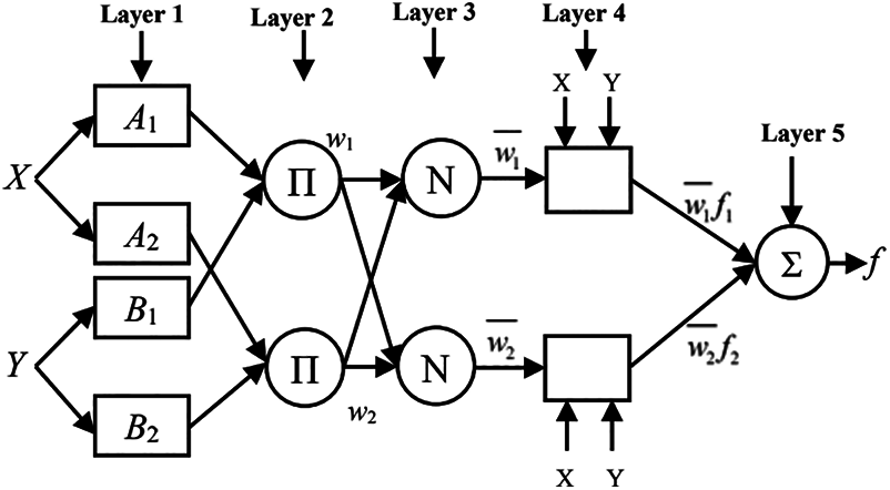
Figure 1: ANFIS architecture
Layer 1: Each node in the first layer is adaptive through an input function and it is expressed as follows:
where,
x is the input for the node i,
A is the linguistic variables
where,
ai, bi, and ci - premise parameters set
Layer 2: The nodes are fixed and it estimates the firing strength for the specified rules. The product of inputs is the output of layer 2 and it is represented as below:
where,
wi - firing strength.
Layer 3: Similar to layer 2, the layer 3 consists of fixed node, where each node estimates the fraction of firing strength and the sum of all firing strength. Hence, the normalised function on this fraction provides the output at layer 3:
Layer 4: The nodes are adaptive and the function of each node is represented as below:
where,
w - layer 3 output
{pi, qi, ri} - Parameter set.
Layer 5: The last layer consists of a single node that estimates the summation of entire incoming signal, and it is represented as below:
The initial settings of M2M network defines the reconfiguration patterns via its network interface and connections with 5G spectrum. The BS-PU is situated in the external zone of M2M and is it designated as heterogeneous one. The PU/SU are allowed to scatter into regular, advanced or pro-level zones with an increasing order of their energy consumption with varying heterogeneity levels.
3.1 Reconfigurable Data Packet Transmission
In this section, we design the resource allocation to a M2M that chooses optimal spectrum to connect and route the data to cloud via 5G spectrum. The resource allocation is done on a regular basis to handle the sensitive information of the M2M on its considered cross-layers. Sometimes the resource allocation with additional network functions leads to increased calculation cost and lowered network throughput. Hence, to avoid such constraint, ANFIS modelling is used in the network that optimizes the radio resource allocation for each M2M device, thereby rescheduling occurs until steady state of heterogeneity is achieved. The distributed central controller is responsible for maintaining the state of heterogeneity with optimal adaptation of network to the allocated resource to a device and it is expressed as below:
where,
R(t) - reconfiguration threshold of M2M at time t,
D - users probability to be in idle model, and at initial instance D is set as 0.1.
r > 0 is the adaption of resource allocation at idle time.
The threshold level-based resource allocation allows the M2M network to be reconfigured heterogeneously to allow for smarter resource allocation that includes the following sections:
The ANFIS assisted resource allocation provides coordination between the network and MAC layer to determine the appropriate rule for allocating the resources to M2M device. This re-configures the M2M topology and requires regular updates using topology discovery. The often-updated M2M helps to precisely develop responses to the resource allocation path in the ML-based resource allocation mechanism. To collect M2M information from the network layers, distance to the BS, residual power, distance between BS-PU and BS-PU, epochal information, frequency of operation of the M2M controller in licensed and unlike the licensed band is used. The BS controller in PU and SU/CR reacts to the Hello message by iteratively updating the whole M2M with current network information.
The M2M devices are designed with heterogeneous residual energy resources to ensure that distributed ANFIS controllers receive data from idle cells and periodically broadcast the status. The data on ANFIS controller on allocation of resource to a M2M is integrated as a database table, which ensures that the cells are in sleep mode due to lack of data in the previous epoch. Then a wake-up message in the mobility-based environment is delivered to the sleep mode cell requiring quick location information. The frequencies of resource allocation exchange rates depend completely on a particular period of time in the static cell. The ANFIS is initiated in accordance with network stability, to change the interval rate of resource allocation.
The settling phase calculates the resource allocation of PU and SU clusters with M2M architecture. It also basically calculates the synchronization of the M2M stability controllers. Optimum cell clustering provides ML-assisted resource allotment path based on the sensitive information provided by M2M. The ML takes further into account the cell heterogeneity to use the residual resources of M2M efficiently.
In the maintenance phase, the dispersed controllers gather information on M2M heterogeneity. The settling phase then uses the following equation to estimate the average level of energy in the network resources:
ER(cb,k(n)) - Residual energy of PU/SU.
The controllers apply ANFIS when formulating the resource allocation to maximize the FPU centrality. The study employs parameters of PU cell values with M2M network parameters for calculation of the FPU centrality as described before, and then the degree of centrality. To maximize the resource allocation, the higher degree of centrality is maintained. In order to acquire the appropriate location of FPUs, the FPU may establish the indexing rate of centrality. The centrality is therefore regarded as the average PU source message ratio that goes to each of its destination SU through another FPU and it given as below:
where,
S-D - optimal resource allocated for data transmission between PU and SU,
S-DFPU - optimal resource between FPUs.
The distributed layer is constructed on the network layer to support the ANFIS in the selection of the optimal resource allocation with the selection of potential CFPU and it is selected based on following criteria:
where,
P(j) – selection probability at final CHs.
n∈CFPU - PU sets in selecting the best
The ANFIS resource allocation follows the same resource allocation procedure throughout the full iteration of M2M. In determining cost-effective settings, the main focus is the equal distribution of loads among PUs with low resource use and low energy consumption.
The intra-cluster communication cost is expressed as:
The inter-cluster communication costs of
The M2M network with total communications cost is evaluated as below:
The distributed controls tend to co-ordinate themselves in order to reduce communications costs and the following disparities constitute the minimum costs in communication:
The aforementioned inequality describes the NP-Hard problem and hence the study employs a greedy strategy runs to test whether the allocated resource is an optimal one. At this time, the study focuses exclusively on the ability to process with a specific quantitative value Δmax. This restricts the ANFIS controller, where it is expressed as below:
Thus, the rule setting at the ANFIS algorithm reduces communication costs greatly to extend the network life with higher cost effectiveness of residual resources.
After FPUs are settled at the settling stage in the resource allocation forward rules, the actual transmission for traffic takes place in the transmission stage. The PUs gets the M2M information from the controller with its multi-sensor systems. The PU configures its communication settings when the controller is deployed. Hello packet sharing and the actual data delivery are monitored iteratively by ANFIS controller. The threshold-value at the controller defines the analytical process for the assignment of resources based on the PU’s sensitivity. The SU selects and compares the threshold value to the random number generated. The threshold value determines how reports sensed by PU are generated. During this phase, the relevant data is then processed and forwarded immediately to other PU’s. The study maintains the property of data transfer in multi-path communication between clusters. At times, it is possible to directly transmit transmission to the BS-SU to prevent delays. When the sensed data reports contemplate priority on resource adjustments, then the threshold value generations are based on the priority of the critical data are performed at the settling stage. Finally, the MAC layer leads you to probable delay free transmission of the controller.
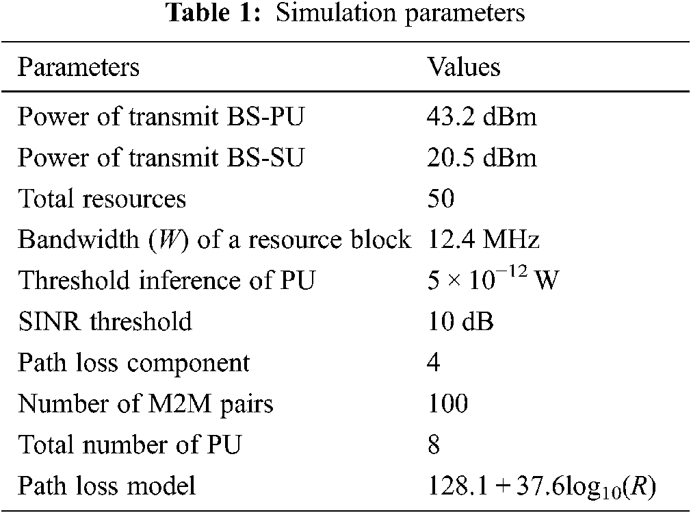
Various PUs originates the M2M and it gets delivered to different BS-SUs. The flow of TCP or CBR ends at 9 min and this allows the packets emitted to reach its appropriate BS-SU. Two different misdirected resource with large length is set in the network in order to ensure that more sessions meet them. The direction of resource allocation path changes from clockwise direction to anticlockwise direction, when the M2M enters the misdirected resource. The parameters for simulation are given in Tab. 1.
4.1 Performance of ANFIS with M2M Pairs
Two different misdirected resources are set with a length of 60 m at the network center and the M2M is varied between 40 (minimum threshold level) and 100.
Fig. 2 shows the results of energy consumption of ANN, FIS, and ANFIS with varying M2M pairs. It is simple to see how much more ANN energy is consumed than FIS. The following can be explained: FIS stops data from being transmitted along the resource allocation borders in scenarios involving various M2M pairings, so decreasing the radius of allocation and thus saving energy. Compared to FIS, our system assigns radio resources to M2M on two separate routes that cross two sides of the resource assignment holes with reduced data collisions accordingly. This reduces retransmission energy use.
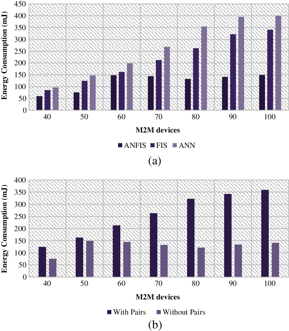
Figure 2: Energy consumption (a) between machine learning models (b) with and without M2M pairs
Fig. 3 shows the results of network lifetime between the existing ANN, FIS, and proposed ANFIS with various M2M pairs. The results reveal that the network life of both the ANFIS and the FIS is much longer than that of ANN. This is because both of them travel over energy-efficient multi-way radio resources to each M2M rather than one ANN route, hence balancing energy conservation amongst networking nodes. It avoids unintentional road collisions because these two paths are on opposite sides of the resource allocation holes, increasing the energy consumption of each node on paths.
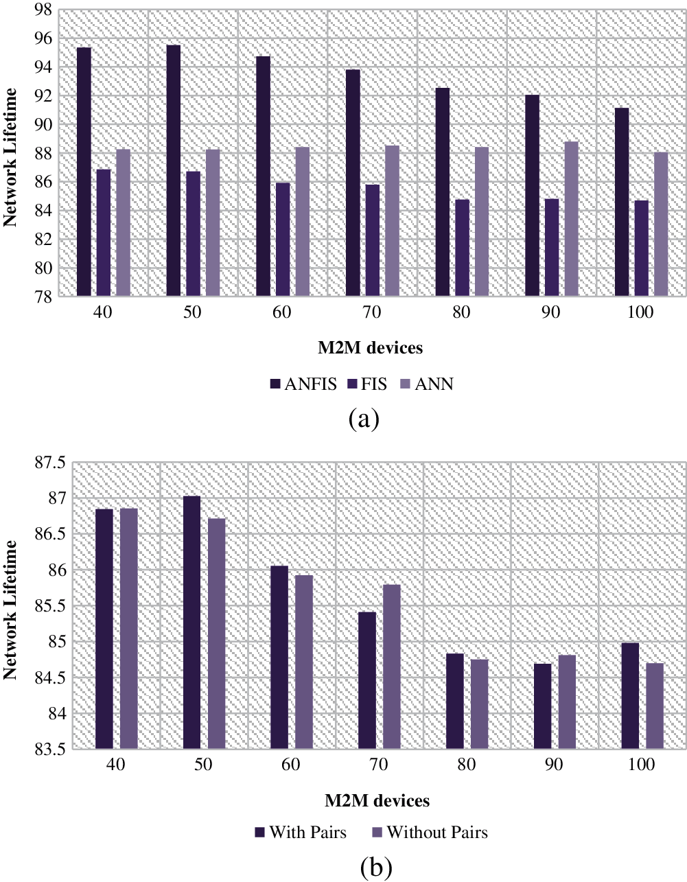
Figure 3: Network lifetime (a) between machine learning models (b) with and without M2M pairs
Fig. 4 shows the results of packet delivery ratio between the existing ANN, FIS, and proposed ANFIS with various M2M pairs. With the increasing number of M2M, several M2M may at the same time avoid non-optimal allocation of resources. This is mostly due to data collisions that occur at the resource allocation border of data delivery. To make it easier to understand the collisions. The radio resources in our approach are transferred to the anchor nodes on the two sides.
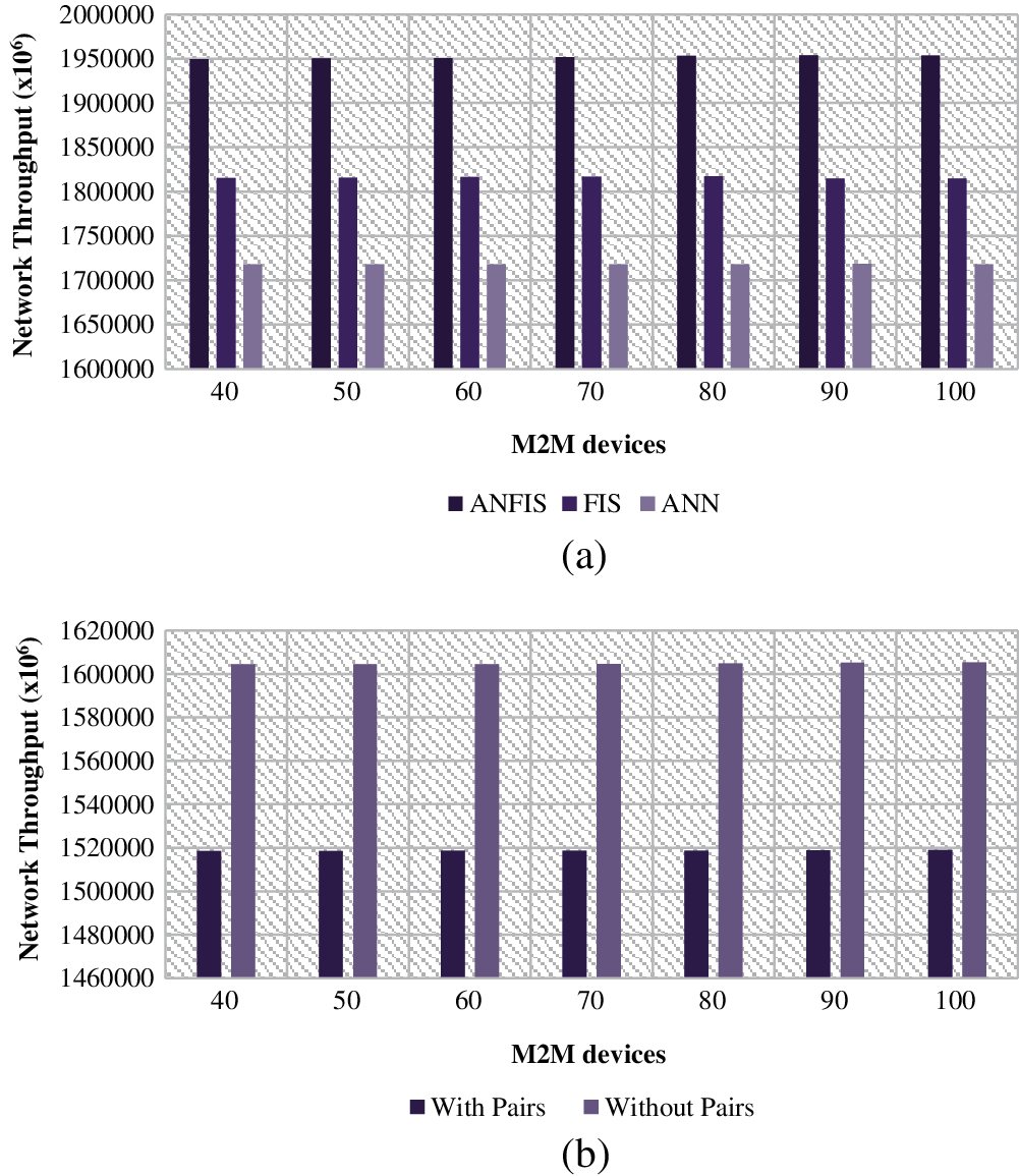
Figure 4: Throughput (a) between machine learning models (b) with and without M2M pairs
Fig. 5 shows the results of delay between the existing ANN, FIS, and proposed ANFIS with various M2M pairs. The findings show that, when the number of M2M is greater than 3, our scheme has the lowest delivery time compared to ANN and FIS. The performance discrepancy between ANN and FIS is mostly based on two reasons. First, to guide data supply, we offer two node-disjoint anchor lists, considerably reducing the path to resource allocation. Secondly, we are going through two separate spaced paths on two sides of resources assignment holes to M2M.
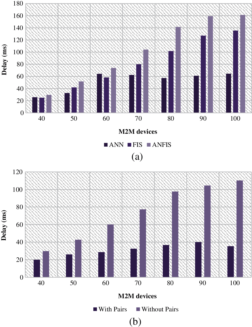
Figure 5: Delivery delay (a) between machine learning models (b) with and without M2M pairs
In this paper, we ANFIS is used to overcome the limitation of radio resource allocation by optimal allocation of resources with severe consideration on various parameters destined for optimal radio resource. The ANFIS controller acts as a central controller that implies the resource allocation with its rules on the M2M devices. The simulation on various communicator scenarios shows the efficacy of ANFIS system on allocation 5G resources to M2M model. The results show that the proposed model achieves higher level of allocating the resources than other existing methods in terms of reduced network delay, increased throughput, packet delivery rate and energy efficiency. In Future, we are going to propose the radio resource allocation models in 5G network using ANFIS with IoT models.
Acknowledgement: Thanks to the reviewing committee for their valuable points and notes.
Funding Statement: The author received no specific funding for this study.
Conflicts of Interest: The authors declare that they have no conflicts of interest to report regarding the present study.
1. A. Karimi, K. I. Pedersen and P. Mogensen, “Low-complexity centralized multi-cell radio resource allocation for 5G URLLC,” in IEEE Transactions on Wireless Communications and Networking Conf. (WCNCSeoul National University, South Korea, pp. 1–6, 2020. [Google Scholar]
2. R. Dong, C. She, W. Hardjawana, Y. Li and B. Vucetic, “Deep learning for radio resource allocation with diverse quality-of-service requirements in 5 g,” IEEE Transactions on Wireless Communications, vol. 20, no. 4, pp. 2309–2324, 2020. [Google Scholar]
3. S. E. Elayoubi, P. Brown, M. Degheland and A. Galindo-Serrano, “Radio resource allocation and retransmission schemes for URLLC over 5G networks,” IEEE Journal on Selected Areas in Communications, vol. 37, no. 4, pp. 896–904, 2019. [Google Scholar]
4. H. Malik, M. Alam, Y. Le-Moullec and Q. Ni, “Interference-aware radio resource allocation for 5G ultra-reliable low-latency communication,” in IEEE Globecom Workshops (GC WkshpsAbu Dhabi, UAE, pp. 1–6, 2018. [Google Scholar]
5. M. Elsayed and M. Erol-Kantarci, “AI-Enabled radio resource allocation in 5G for URLLC and eMBB users,” IEEE 2nd 5G World Forum (5GWF), pp. 590–595, 2019. http://dx.doi.org/10.1109/5GWF.2019.8911618. [Google Scholar]
6. A. Aijaz, “A radio resource slicing framework for 5G networks with haptic communications,” IEEE Systems Journal, vol. 12, no. 3, pp. 2285–2296, 2017. [Google Scholar]
7. Y. Han, S. E. Elayoubi, A. Galindo-Serrano, V. S. Varma and M. Messai, “Periodic radio resource allocation to meet latency and reliability requirements in 5G networks,” in IEEE 87th Vehicular Technology Conf. (VTC SpringPorto, Portugal, pp. 1–6, 2018. [Google Scholar]
8. M. Moltafet, S. Parsaeefard, M. R. Javan and N. Mokari, “Robust radio resource allocation in MISO-sCMA assisted C-rAN in 5G networks,” IEEE Transactions on Vehicular Technology, vol. 68, no. 6, pp. 5758–5768, 2019. [Google Scholar]
9. M. Moltafet, R. Joda, N. Mokari, M. R. Sabagh and M. Zorzi, “Joint access and fronthaul radio resource allocation in PD-nOMA-based 5G networks enabling dual connectivity and CoMP,” IEEE Transactions on Communications, vol. 66, no. 12, pp. 6463–6477, 2018. [Google Scholar]
10. Y. Li, E. Pateromichelakis, N. Vucic, J. Luo, W. Xu et al., “Radio resource management considerations for 5G millimeter wave backhaul and access networks,” IEEE Communications Magazine, vol. 55, no. 6, pp. 86–92, 2017. [Google Scholar]
11. C. Desogus, M. Anedda, M. Murroni and G. M. Muntean, “A traffic type-based differentiated reputation algorithm for radio resource allocation during multi-service content delivery in 5G heterogeneous scenarios,” IEEE Access, vol. 7, pp. 27720–27735, 2019. [Google Scholar]
12. Z. H. Hussien and Y. Sadi, “Flexible radio resource allocation for machine type communications in 5G cellular networks,” in 26th Signal Processing and Communications Applications Conf. (SIUCesme, Izmir, Turkey, pp. 1–4, 2018. [Google Scholar]
13. S. Matoussi, I. Fajjari, N. Aitsaadi, R. Langar and S. Costanzo, “Joint functional split and resource allocation in 5 g cloud-ran,” in IEEE Int. Conf. on Communications (ICCShanghai, China, pp. 1–7, 2019. [Google Scholar]
14. Y. Zhou, Z. M. Fadlullah, B. Mao and N. Kato, “A deep-learning-based radio resource assignment technique for 5G ultra dense networks,” IEEE Network, vol. 32, no. 6, pp. 28–34, 2018. [Google Scholar]
 | This work is licensed under a Creative Commons Attribution 4.0 International License, which permits unrestricted use, distribution, and reproduction in any medium, provided the original work is properly cited. |