DOI:10.32604/iasc.2022.022288
| Intelligent Automation & Soft Computing DOI:10.32604/iasc.2022.022288 | |
| Article |
Mobile Robots’ Collision Prediction Based on Virtual Cocoons
1Department of Automation, Faculty of Electrical and Electronics Engineering, Kaunas University of Technology, Kaunas, LT-51367, Lithuania
2Department of Electrical Power Systems, Faculty of Electrical and Electronics Engineering, Kaunas University of Technology, Kaunas, LT-51367, Lithuania
3Department of Electronics Engineering, Faculty of Electrical and Electronics Engineering, Kaunas University of Technology, Kaunas, LT-51367, Lithuania
*Corresponding Author: Virginijus Baranauskas. Email: virginijus.baranauskas@ktu.lt
Received: 03 August 2021; Accepted: 06 September 2021
Abstract: The research work presents a collision prediction method of mobile robots. The authors of the work use so-called, virtual cocoons to evaluate the collision criteria of two robots. The idea, mathematical representation of the calculations and experimental simulations are presented in the paper work. A virtual model of the industrial process with moving mobile robots was created. Obstacle avoidance was not solved here. The authors of the article were working on collision avoidance problem solving between moving robots. Theoretical approach presents mathematical calculations and dependences of path angles of mobile robots. Experimental simulations, using the software Centaurus CPN, based on colored Petri nets, has shown, that the possible conflict can be predicted in advance using calculations of the angle of movement of two possibly colliding cocoons. Authors of the paper presents and explains experimental simulations, where robots are moving in different path angles, which intersects each other. Proposed collision avoidance algorithm solves collision avoidance task using several possibilities. Software Centaurus CPN gives possibility to stop simulation of manufacturing process in the place where it finds possible collision between two cocoons. In order to check correctness of proposed collision prediction and avoidance algorithm, further simulation is done step by step, while situation is solved. Simulated manufacturing process is continued till new possible collision is obtained.
Keywords: Robots control; prediction of conflicts; multi-robot system; protective sheath “cocoon”; robot motion control
Multi-robot path planning and motion coordination addresses the problem of how teams of autonomous mobile robots can share the same workspace while avoiding interference with each other and/or while achieving group motion objectives. Nearly all applications of multiple autonomous mobile robots must address this issue of motion coordination, either explicitly or implicitly. Multi-robot path planning [1–3] and teaming have been extensively studied since the 1980s [4–6].
In modern industry, robots or robotic systems are integrated alongside traditional control systems to increase the quality and efficiency of production. Especially considering the challenges of Industry 4.0, where the application of robots is one of the most actual [7]. Most of the robots are stationary and have dedicated fixed working places. Improvement of industrial manufacturing increasingly evolves an application of mobile robots, which transfer products from one part of the production to the next for further processing. Mobile robot teams share the same workspace when performing tasks, so it is important to plan the path of multirobots and coordinate their movements to avoid interference with each other and achieve the goals of group movement [1,8]. Such robots are usually controlled by a supervision control system that communicates with each mobile robot on the field [9–11]. Collision avoidance is one of the most important tasks in the manufacture with mobile robots. Effective usage of mobile robots requires many functionalities such as localization, map building, planning, and collision avoidance. The authors of the work proposed to use a supervision system, which should execute the mentioned tasks. How-ever, the authors of this work restrict themselves to one task, i.e., solving a collision avoidance task between moving robots.
Usually, the supervision system calculates the motion trajectories of mobile robots to carry out the required work tasks and provide information to each robot separately [6,11–13]. The motion trajectory of one mobile robot is designed to avoid a potential collision with static obstacles (columns, walls, partitions) when the environment is known. These types of collisions are addressed through vector marks [14,15], which determine the shortest possible path of the robot trajectories. Dynamic obstacles, which can vary in size and location, can appear when more than one robot is used in the same known environment. Therefore, new approaches are needed to solve the collision prediction task [3,16–18]. Certain predefined rules of the robot motion must be created and applied to avoid collisions. There are many options for that, i.e., it is possible to steer around the obstacle, pause or stop the motion, or even execute the task.
The systems, which can predict a possible collision, are necessary for the successful functioning of the manufacturing process. The conflict situations of mobile robots can be avoided using the rules [14], but there are many other methods, which refer to the advanced prediction of the possible robot collision [19–22]. The authors of the work [11] estimate so-called conflict-free proportions based on the measured velocity and orientation axes. The Fuzzy method was applied to underwater robots [16], where the VFF (Virtual Force Field) method for the navigation of underwater robots was applied. The authors of the work [5] have proposed an in-line motion planning algorithm, which effectively solves possible collision problems. These solutions are facilitating certain supervision systems that can perform virtual-time simulation and make decisions in advance to prevent possible collisions. Work [23] describes robot path planning in confined spaces and solves the problem of communication loss. The authors of the work [24] present their solution for a swarm of the robot, which is based on Ant colony algorithm. In this case, all robots seek one goal.
From the mentioned articles, it is obvious that there are many tested algorithms for mobile robots’ path planning in a known or unknown environment. The usage of a supervisory system allows researchers to solve information distribution and communication problems. Small parts and ideas of these researches were merged while solving the mobile robot’s path planning and collision avoidance problem in the simulated manufacturing process. The main differences from the mentioned works of many researchers are: simulations are done in a known environment with a swarm of robots, which are seeking their own goals; no additional equipment in manufacturing for the robot’s navigation is necessary; collision avoidance is analyzed when two robots collide.
The possible collision of two moving robots can be simulated in advance using a supervision-based control system, and the motion trajectories of those robots can be changed accordingly. The authors of the paper have designed a special virtual environment, based on colored Petri nets, called “CentaurusCPN”, which consists of various robot navigation, possible collision estimation, and forecasting tools. The mobile robots in the virtual environment are modeled as close as possible to real robots. Virtual robots have all physical properties, needed to simulate real-world situations. Each mobile robot in a simulated system has its number, the system generates the priority of the task.
The concept of virtual cocoons is used in the publication to evaluate the collision criteria of two robots. The motion of the mobile robots is controlled by the supervision system, which autonomously envelops each robot in an individual virtual cocoon.
2 Cocoon Collision Rules for Conflict Prevention
A centralized method of mobile robots’ conflict prediction is proposed. Flexible manufacturing is chosen as an analyzed system, where mobile robots execute tasks given by the central control system services industrial process. In this case, solving mobile robot navigation problems can be transferred to a supervisory system. The supervisor-based system is solving mobile robots’ navigation problems and searches for the shortest path using colored Petri nets [14,15] in a virtual environment. All parties of the virtual system are functioning asynchronously. Usage of colored Petri nets enables, in a virtual environment, to solve part of mobile robot navigation problems. As a result, the final coordinates of movement to the target point in the shortest path are established, but the conflict situations with dynamic obstacles are not solved in this paper.
For the detection of possible conflicts, the authors suggest using knowledge of the principles of finding obstacles in the darkroom. The collision between two mobile robots is fixed only then, when the robots touch one other, as shown in part a of Fig. 1. There are two possibilities to react to this situation in this case. Such a situation is modeled in a virtual environment. The authors of the article offer to put the tegument or security zone for the mobile robot. Then there is the possibility to forecast possible collisions. If two teguments, which are named as cocoons, touch one another, it can be said that mobile robot goes closer to each other, as shown in part b of Fig. 1. If the supervisory system knows the directions of mobile robots’ movement, there are all possibilities to forecast possible collisions. It is possible to conclude exactly when the conflict between mobile robots will occur or not if cocoons collide.

Figure 1: Examples of collisions between two mobile robots: without cocoon (a) and with cocoons (b) mathematical representation of the condition of a robot passing without collision
The virtual environment gives the possibility to predict and analyze the movement of the mobile robots, so their actions can be forecasted in advanced time. The problem of collision is solved much faster in a virtual environment than in the real world; therefore, using specified methods and defined rules, the conflict is solved even when real robots are standing in starting positions. After modeling, coordinates of the path are sent to real mobile robots, which can move using this information without collision with each other. There is no guarantee that mobile robots will move exactly according to the given coordinates and they will not change due to the asymmetry of the wheels or other reasons. In this case, the supervisory system must know the coordinates of the mobile robot in real-time, and if they deviate from the given, it must correct the movement paths according to the changed coordinates.
where b0 and a0-distances between robot center and paths intersection, R – robot radius, α, and β-robot movement path direction angles.
When cocoons collide, there can be situations when robots will collide or will not collide, as shown in Fig. 2.

Figure 2: Possible situations after the collision of the cocoons, when the directions of the movement and path intersection point are in the same place. Robots do not collide in situations (a) and (b), and the robots collide in situation (c). The collision of the robot depends on the angles of the cocoons collision
Situation (a) in Fig. 2. Robot A is further from the path’s intersection point; robot B is closer to it when their cocoons contact each other. In a virtual environment, the authors show the next positions of each mobile robot, starting from this point of time (positions 1 .. 4, when robots move at the same speed). Robot B moves earlier through the intersection of the paths and the robots do not collide, although cocoons collide.
Situation (b) in Fig. 2. Robot B is further from the path’s intersection point; the robot A is closer to it when their cocoons contact each other. In a virtual environment, the authors show the next positions of each mobile robot, starting from this point of time (positions 1 .. 4, when robots move at the same speed). Robot A moves earlier through the intersection of the paths and robots do not collide, although cocoons collide.
In situation c of Fig. 2 robot B is further from the path’s intersection point, the robot A is closer to it when their cocoons contact each other. In a virtual environment, it is shown the next positions of each mobile robot, starting from this point of time (positions 1 .. 4, when the robots move at the same speed). The robots collide. The distances between robots and the paths intersection point are not sufficient, because condition (1) is not fulfilled.
Fig. 2 shows that the usage of cocoons enables to forecast of possible collisions, but in one case there is no need to take any action. In the other case, there is a need to take some actions to avoid a collision. The question is, what are the likely conditions of mobile robots’ collision if two cocoons collide?
Fig. 2 shows the different path angles of the robot when connecting their paths and centers of the robots into one line. When paying attention to these angles, it’s possible to notice that there is an angle difference between collided cocoons even if the robots collide or not. Therefore, using these angles there is the possibility to predict when a real collision between robots will be when cocoons collide. Angles are measured from the vector of robot movement direction against clockwise until the line between centers of the mobile robots. After converting the angles, the situation shown in Fig. 3, is obtained.

Figure 3: The first robot is closer to the point of intersection of routes
In such a way, two moving robots in a known environment potentially collide. The potential conflict between them depends on the movement routes crossing the angle α–β and the distance to the path’s intersection point [14]. Fig. 2 shows two potential conflicts: the first one, when the first robot is closer to the point of intersection of routes; the second one when the first robot is further from the point of intersection of routes. Suppose that each robot “fits” into the circle with radius R, the size of the cocoon is kR, where k is a multiplier of the cocoon, as shown in Fig. 3. According to this, a robot, which is closer to the intersection of routes, should have priority to cross the intersection.
Bypassing robots without conflict clause [4] derived equations describing the distances to the robot cocoon intersection point preconflict situation. Expressions (2) and (3) refer to the preconflict situation. If the conflict can be predicted by the distance to the inter-section of routes, it can be assumed that the conflict can be predicted by cocoons intersection angles γ, δ. It consists of the angles between the robot moving direction and the point of intersection (Fig. 3).
For the calculation of γ, δ angles, the trigonometric semi-perimeter p (4) and the angles of a triangle formula are used, over them expressing the angles. Expressions (5) and (6) are obtained.
Since the collision in Fig. 1 part c, draws a triangle, a high change angle of a triangle occurs. It occurs when a robot, whose abscissa is equal to “a” and moving by the abscissa axis passes through the point intersection of tracks. The collision, which is shown in Fig. 2 also draws a triangle-like area, where a high change in the angle of a triangle occurs when a Robot 2 is placed at the intersection of routes and b = 0. Therefore, the high change in the angle of the triangle occurs when a = 0 or b = 0. At what angle α-β will be an exchange of a triangle can be calculated by (7) equation.
After making the appropriate changes, between the final angle the intersection of routes expression (9) is obtained.
From the expression (9) authors notice, that the angles of a triangle suddenly changes, and the triangle disappears at that moment. This situation is outlined that it depends only on k. Sudden change in angle limit dependence on the size of the cocoon. A preconflict situation is planned to solve according to the values of the triangle angles. In this case, the triangle disappears and other conditions of the establishment will be used.
Eqs. (2) and (3) are converted to a coordinate system. Model, which views the preconflict situations of the robots, is modeled. This model, according to Eqs. (5) and (6), gives meaning to these angles. Angles of the cocoon collision are measured de-pending on the direction of the movement, according to the clockwise. The values of the angles can vary from 0° to 360° and the obtained results are not real angles of the triangle. This is shown in the modeling results in Fig. 4.

Figure 4: Dependence of the marginal triangle angle, when cocoons collide, on the paths intersection angle when the cocoon size is 2R
Cocoons intersection angle is converted to triangle angles and the obtained result is shown in Fig. 5.
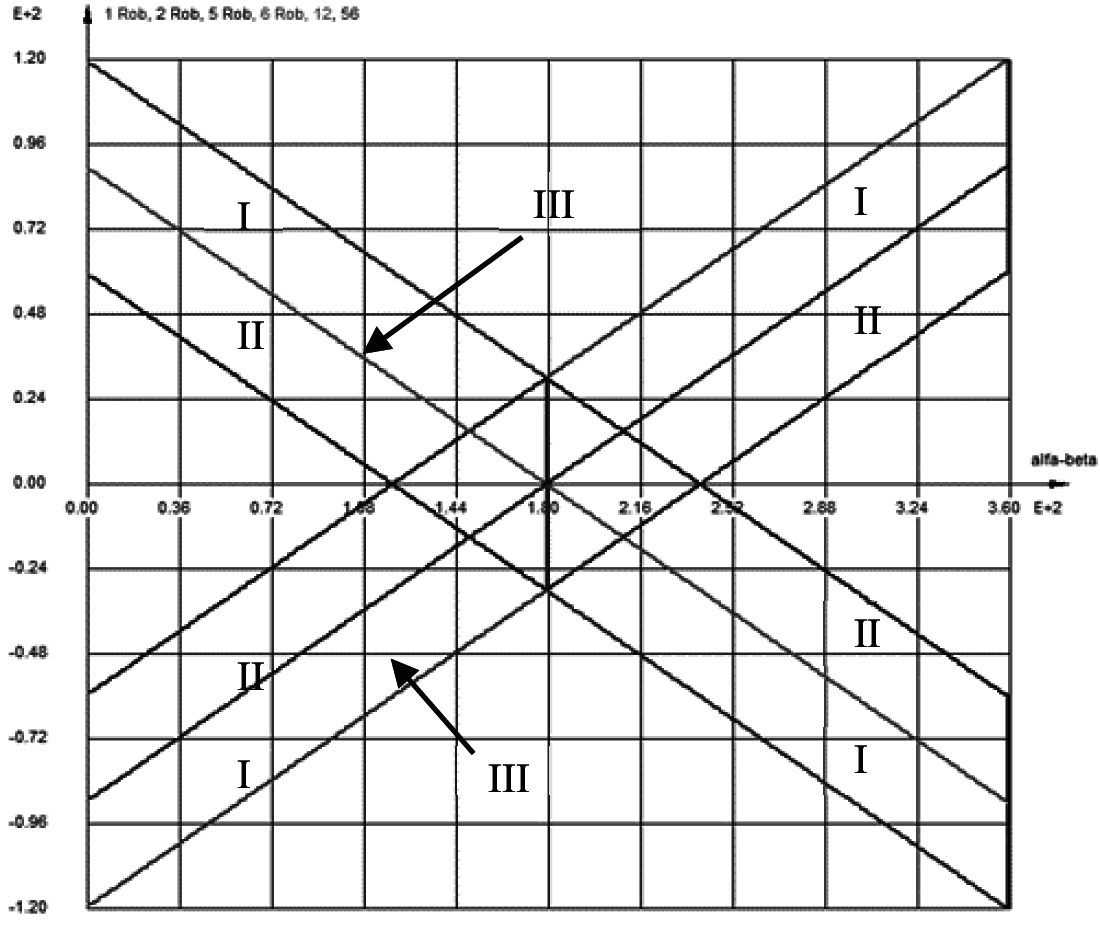
Figure 5: Limit values of the mobile robot cocoons collision of transformed angles to triangle angles, depending on the angle of the moving mobile robot trajectories
This Fig. 5 illustrates the calculated triangle angles, in the state of co-coon contact before robot collision and the paths intersection angle α–β, varying from 0° to 360°. During modeling, the size of the cocoon radius is two times bigger than the robots’ radius. Distance equations used in calculations, were obtained according to the condition of robot conflict detection (1), described in the second chapter. Obtained values of the angles can be treated as limits, which could indicate angle limits, where real robot collisions could be possible.
The transformed angles are calculated after a sudden change of angle of the triangle, using Eq. (9). When the cocoon diameter is twice bigger, that robot diameter, the graph, shown in Fig. 5, is obtained.
From Fig. 5 the dependencies when robot I has priority to robot II, are got. If the angle is converted, the robot, which is in the field of I, has priority over the other, whose angle in the field is in II. If the angles are identical and the value is on line III, robots have equal rights and priority; therefore, there should be other criteria.
It is possible to predict a real collision between the robots by the difference of trans-formed robots’ cocoons angles. The angle value can be determined from Fig. 4, and the mathematical expression presented in (10).
This expression shows, that the limit angle LA varies with the coefficient k. Graphical dependence of the limit angle between k is shown in Fig. 6.
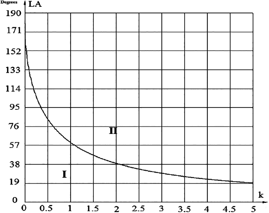
Figure 6: Dependence of limit angle LA on cocoon size (angle difference area I when robot conflict is predicted, angle difference area II when no conflict is expected)
Fig. 6 shows dependence: when the cocoon size is increasing, LA value decreases. It leads to the following conclusion: if the diameter of the robot cocoon is increasing, the number of robot conflicts, compared to the number of detected cases of cocoon conflicts, will be low. It is appropriate to choose the right size cocoon.
3 A Conflict Resolution Dependence on the Contact Angle of Cocoons
To detect a possible collision of two moving robots, it is necessary to know the internal peer angle of the triangle, whose vertices consist of three points, i.e., the centers of robots and the intersection point of routes when the cocoons are contacting.
Let’s analyze the situation of two moving robots (Fig. 7). Let’s suppose, that the value of γ belongs to robot R1 and δ belongs to R2 robot. According to these angles, the direction of the conflict approach can be set. If the value of robot angle γ and δ is more than 180°, the obstacles are approaching from the right. If a value of robot angle γ and δ is less than 180°, obstacles are approaching from the left. If the robot angle γ and δ are equal to 180°, then the obstacle is approaching from the opposite side.
According to the cocoons contact angles of the conflict probability condition, as can be seen from expression (10), LA depends on the size of the coefficient k. The potential situation for conflict depends on the diameter of the cocoon. However, it should be noted, that this condition is suitable, when both robots are moving toward the intersection of the movement vector and when the robot, whose angle is smaller, is moving away from the point of routes vector intersection. When (10) condition is not fulfilled, there are two conditions for potential collision:
• (γ > δ) and (γ + δ > 90°) and R2 approach to the point of intersection of the movement vector and R1 moving away (example in Fig. 6);
• (γ < δ) and (γ + δ > 90°) and R2 moving away from the point of intersection of the movement vector and R1 approaching.
There are several possibilities to resolve the conflicts between robots: stopping one of the conflicting robots, one or both conflicting robots has to change the trajectory or change its speed. The solution, when one of the robots stops, is limited. Depending on the cocoon size, the distance to the robot’s point of conflict may be too small to stop one of the robots to solve the conflict. The suspension is not available, when the robot movement vector angle difference in absolute size falls into the range (180°− LA<=…<=180°+ LA) or under Fig. 4, LL<=…<=LH. In this case, a possible solution would only change the path.
4 Algorithm of Collision Avoidance and Experiments
Software “CentaurusCPN” is enabled to solve mobile robot path planning tasks [15]. The calculated path is the shortest according to its length in the current situation, but collisions between robots are not taken into account in work [15]. Authors had to modify the structure of dynamic region description when “cocoons” were started to apply.
An image of the created model for experimental testing of the algorithm is shown in Fig. 8. Fig. 8 shows a production workshop serviced by 17 mobile robots, where from the starting position “1” the robots are directed to the work piece warehouses “2”. Robot transports work pieces according to the free space of the production machine “3” and type of the required part. After manufacturing tasks are executed, the free robot takes the product from “3” and delivers them to the warehouse “4” or to the place of delivery “5”.
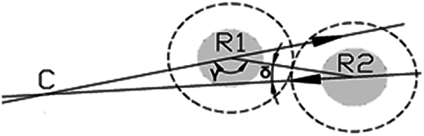
Figure 7: One state of the possible robot cocoons touching states when robots will face each other

Figure 8: CENTAURUSCPN model depicting the production workshop with tracks. 1-Robot service, starting position from sleep position; 2-work piece warehouse; 3-production machine tools; 4-warehouse of finished parts; 5-product collection point for removal; 6-robots paths
The central control system selects the free robot, which is the closest to the original target for the next task, assigning it execution tasks and coordinates. It has been observed that the functioning of a system that uses a supervisory system to solve common or global tasks is much more rational, especially when it comes to systems where navigation and conflict situations are resolved in a known environment.
Fig. 9 shows fragment, servicing for cocoons collisions of the model, i.e., program interrupts are executed in this case. Usually in “CentaurusCPN” and colored Petri nets transition (742 position) can use only the values of incoming tokes from the branches and generate new tokens according to the current situation. If the interrupt is organized, then a transition becomes a place for generating the special token. The token is generated when two cocoons collide. The transition has an inspection expression with the special function DynCnflct( ), which generates the parameters of collided cocoons. When two cocoons collide or touch each other, the function generates a “TRUE” value. This function is used for activation of the transition and serves for further execution of the functions.
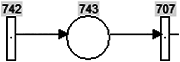
Figure 9: Interrupt model in “CentaurusCPN”. 743-position, 742 and 707-transitions. 742 transition generates interrupt parameters when two cocoons collide
Function DynCnflct( ) generates a function Conflicting, which provides information about conflicting parts:
“REG2”, 5.76672E + 0000, “REG1”, 6.15942E + 0000, 1.50148E + 0001, 8.34228E + 0001, 2.74889E + 0000, 1.49000E + 0001, 8.49000E + 0001
Here: (Name of 1-st robot region), (the angle between the vector of the direction of movement of this region and the vector towards the center of the chord of the intersection of the cocoons), (Name of 2-nd robot region), (the angle between the vector of the direction of movement of this region and the vector towards the center of the chord of the intersection of the cocoons), (abscissa of intersection chord mid), (ordinate of intersection chord mid), (angle of intersection of the traces), (abscissa of point of intersected traces), (ordinate of point of intersected traces).
Using the results of the Conflicting function, the following steps, as shown in Fig. 10, are performed. Block diagram shows the procedure, where “I” shows the beginning of a procedure called “Conflict Resolution”, from which the steps of identifying and resolving all conflicts between them begin. These actions begin with the DynCnflct( ) function, which activates the transition in Petri nets when a cocoon collision is detected.

Figure 10: Functional block diagram of the procedure “conflict resolution”
Step II extracts the cocoon conflict information from the system using the Conflicting ( ) function. In step III, using the previously obtained information, the procedure of con-verting angles into triangular angles is performed by activating the function “angles ( )”. After this procedure, the information obtained in step “IV”, steps “II” and “III” is transmit-ted to the “Conflict ( )” block of the conflict event check between real robots, which results in “YES” or “NO”. A score of “NO” indicates a negative likelihood of conflict, and the “con-flict resolution” procedure ends with a jump to step VII, a “YES” to a future conflict, and then the next step, step V, to type, prioritize, and select the required actions for the conflict to solve. In step VI, the conflict resolution commands are executed according to the conflict type number, after which the “conflict resolution” procedure is completed in step VII.
When two cocoons collide, the function DynCnflct( ) is not stopped until the cocoons separate from each other. To avoid it, a new function BanCnflct( ) is used. This function eliminates recapturing of the same conflicts, using the names of robot regions.
When the cocoons break up, they are reestablished in a state of a possible new conflict between them. If the situation makes it necessary to place the model in such a state that conflicts need to be rerecorded, the ClrCnflcts ( ) function has been created by clearing the conflicts of the required robot cocoon with all previously prohibited conflicts.
These additional functions are included in the list of standard software features. All these mentioned functions are used to capture the contact between the cocoons, but it does not check whether the actual collision of the cocoons will result in a robot collision.
For the convenience of modeling, when dealing with situations with a cocoon, changes have also been made in the software windows: cocoons can be shown or hidden, collisions can be monitored by robots with cocoons or robots without cocoons.
Conditions and algorithms mentioned above are realized in CentaurusCPN by modeling mobile robots’ movement. During experiments, speed of the robots was not changing, the dimensions of the robots with cocoons were the same, there were no noises and other technical problems or disturbances. Experimental testing was done when 2 cocoons collided. The conflict situations were solved between 2 collided robots. Software CentaurusCPN allows communication with mobile robots, but real situation testing was not done. Results of the simulations are shown in Figs. 11–14. These simulations illustrate virtual robot movement in the known environment, indicating their positions in seconds.
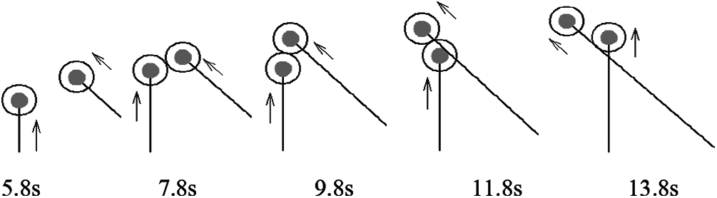
Figure 11: Experimental situation 1

Figure 12: Experimental situation 2
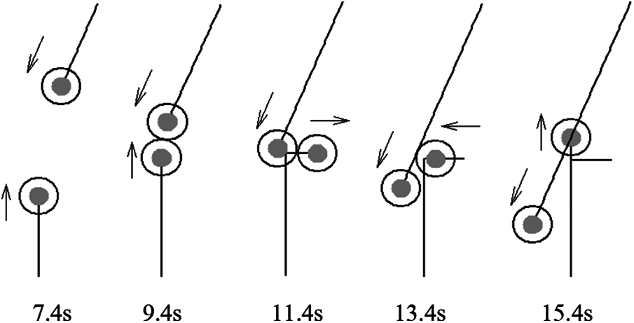
Figure 13: Experimental situation 3
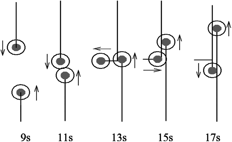
Figure 14: Experimental situation 4
Experimental situation no. 1 (Fig. 11) shows an example where paths of two mobile robots intersect at 45° and the right robot is closer to the paths intersection point, and it has priority. The situation is observed step by step, starting from 5.8 s; after the cocoon collision at 7.8 s, the right robot has priority; at 9.8 s left robot stops to give a path to the right robot; at 11.8 s both robots continue their movement according to the planned path and at 13.8 s the conflict situation is over when both robots proceed their tasks and recede from the intersection point.
Experimental situation no. 2 (Fig. 12) shows an example, where the paths of mobile robots intersect at 90°, the robot located on the right side is closer to the paths intersection point and it has priority. The situation is observed step by step, starting from 7 s; after cocoon collides at 9 s, due to the right robot priority, the robot moving across the ordinate axis stops to pass the robot, moving from the right side; when the robot, that has priority, passes at 11 s began to move; at 13 s collision situation is solved, both robots proceed their tasks and recede from the intersection point.
Experimental situation no. 3 (Fig. 13) shows an example, when the paths of two mobile robots intersect at 157.5°, the robot moving from the top is closer to the path’s intersection point and it has priority. In this case, if any robot will be stopped, the conflict situation will not be solved. The situation is observed step by step, starting from 7.4 s; cocoons collide at 9.4 s; due to the priority of the robot going from the top, the robot at the bottom has to move to the safe right side and give the path at 11.4 s; at 13.4 s robot, going to the top, returns to his previous path and at 15.4 s proceeds his tasks.
Experimental situation no. 4 (Fig. 14) shows an example, where two robots move parallel to close to each other. Robot going to the top has priority. The situation is observed step by step, starting from 9 s; after the cocoons collide at 11 s, due to the priority of the robot, going to the top, another robot moves to its right side at 13 s; at 15 s it returns to its’ path and at 17 s the conflict situation is over a fixed situation, when both robots proceed their tasks.
The authors of the article propose to put a shell or protective zone (cocoon) for each robot in a virtual environment, which makes it possible to predict a near-collision state. If two such shells (cocoons) come into contact, it is clear that the mobile robots are approaching each other. Mathematical expressions have been established for this situation, which al-lows determining the difference between the locations of the robots at the intersection of the tracks, whether the real robots will collide or not.
It has been found that collision prediction can be made based on cocoon collision angles. Angle limits have been set for when robots will collide when they do not. The limit values for these angles depend on the size of the cocoon and decrease as the size of the cocoon increases.
Using the values of cocoon angles, the most appropriate way of stopping, exiting, or complex (both robots take action) future conflict between them is calculated.
Simulation examples demonstrate the logic of cocoon functioning. Part of the conflicts of mobile robots that do not cause cocoon collisions is ignored, the other part predicts collisions when predicting mobile robot collisions: one of the robots is stopped to avoid a collision, otherwise, one of the mobile robots leaves its trace and returns only when the path will be free.
Funding Statement: The authors received no specific funding for this study.
Conflicts of Interest: The authors declare that they have no conflicts of interest to report regarding the present study.
1. L. E. Parker, “Path planning and motion coordination in multiple mobile robot teams,” In: Meyers R. (ed.). Encyclopedia of Complexity and Systems Science, New York, NY: Springer, 2009. [Online]. Available: https://www.researchgate.net/publication/239899962_Multiple_Mobile_Robot_Teams_Path_Planning_and_Motion_Coordination_in. [Google Scholar]
2. L. Tychonievich, D. Zaret, J. Mantegna, R. Evans, E. Muehle et al., “A maneuvering board approach to path planning with moving obstacles,” in Proc. of the 11th Int. Joint Conf. on Artificial Intelligence, Detroit Michigan, USA, vol. 2, no. 1, pp. 1017–1021, 1989. [Google Scholar]
3. J. Borenstein and Y. Koren, “The vector field histogram-fast obstacle avoidance for mobile robots,” IEEE Journal of Robotics and Automation, vol. 7, no.3, pp. 278–288, 1991. [Google Scholar]
4. K. J. Kyriakopoulos and G. N. Saridis, “Distance estimation and collision prediction for on-line robotic motion planning,” Automatica, vol. 28, no. 2, pp. 389–394, 1992. [Google Scholar]
5. P. Glorennec. “Coordination between autonomous robots,” International Journal of Approximate Reasoning, vol. 17, no. 4, pp. 433–446, 1997. [Google Scholar]
6. K. Azarm and G. Schmidt, “Conflict-free motion of multiple mobile robots based on decentralized motion planning and negotiation,” in Proc. of the 1997 IEEE, Int. Conf. on Robotics and Automation, Albuquerque, NM, USA, pp. 3526–3534, 1997. [Google Scholar]
7. E. K. Zervoudi, “Fourth industrial revolution: Opportunities, challenges, and proposed policies,” Industrial Robotics-New Paradigms, Antoni Grau and Zhuping Wang, IntechOpen, 2020. [Online]. Available: https://www.intechopen.com/chapters/70877. [Google Scholar]
8. D. Albani, W. Honig, D. Nardi, N. Ayanian and V. Trianni, “Hierarchical task assignment and path finding with limited communication for robot swarms,” Applied Sciences, vol. 11, no. 7, pp. 1–21, 2021. [Google Scholar]
9. Y. Guo and L. E. Parker, “A distributed and optimal motion planning approach for multiple mobile robots,” in Proc. of the 2002 IEEE, Int. Conf. on Robotics and Automation, Washington, DC, USA, pp. 2612–2619, 2002. [Google Scholar]
10. R. C. Hill and S. Lafortune, “Scaling the formal synthesis of supervisory control software for multiple robot systems,” in Proc. of 2017 American Control Conf. (ACCSeattle, WA, USA, pp. 3840–3847, 2017. [Google Scholar]
11. P. Satish and K. Madhava, “Multi robotic conflict resolution by cooperative velocity and direction control,” in Mobile Robots: Perception & Navigation, edited by: Sascha Kolski, Plv/ARS, Germany, pp. 637–666, 2007. [Online]. Available: https://www.intechopen.com/chapters/157. [Google Scholar]
12. Y. Tatsumoto, M. Shiraishi, K. Cai and Z. Lin, “Application of online supervisory control of discrete-event systems to multi-robot warehouse automation,” Control Engineering Practice, vol. 81, no. 1, pp. 97–104, 2018. [Google Scholar]
13. J. A. Dulce-Galindo, M. A. Santos, G. V. Raffo and P. N. Pena, “Autonomous navigation of multiple robots using supervisory control theory,” in Proc. of 2019 18th European Control Conf. (ECCNaples, Italy, pp. 3198–3203, 2019. [Google Scholar]
14. S. K. Bartkevičius, Ž. Jakas and K. K. Šarkauskas, “Vector approach of collision prognosis of mobile robots,” Electronics and Electrical Engineering, vol. 121, no. 5, pp. 75–78, 2012. [Google Scholar]
15. S. Bartkevicius, O. Fiodorova, A. Knys, A. Derviniene, G. Dervinis et al., “Mobile robots navigation modeling in known 2D environment based on petri nets,” Intelligent Automation and Soft Computing, vol. 24, no. 2, pp. 241–248, 2018. [Google Scholar]
16. K. Kyoung-Youb, C. Jeongmok and J. Joongseon, “Collision avoidance of moving obstacles for underwater robots,” Systemics, Cybernetics and Informatics, vol. 4, no. 5, pp. 86–91, 2006. [Google Scholar]
17. J. Berg, L. Ming and D. Manocha, “Reciprocal velocity obstacles for real-time multi-agent navigation,” in Proc. of ICRA Robotics and Automation, Pasadena, CA, USA, pp. 1928–1935, 2008. [Google Scholar]
18. Z. Yi, Z. Tao, J. Song and L. Xiaqin, “A new bug-type algorithm for navigation of mobile robots in unknown environments containing moving obstacles,” Industrial Robot, vol. 39, no. 1, pp. 27–39, 2012. [Google Scholar]
19. P. Fiorini and Z. Shiller, “Motion planning in dynamic environments using velocity obstacles,” International Journal on Robotics Research, vol. 17, no. 7, pp. 760–772, 1998. [Google Scholar]
20. D. Hsu, R. Kindel, J. Latombe and S. Rock, “Randomized kinodynamic motion planning with moving obstacles,” International Journal of Robotics Research, vol. 21, no. 3, pp. 233–255, 2002. [Google Scholar]
21. M. Defoort, A. Kokosy, T. Floquet, W. Perruquetti and J. Palos, “Motion planning for cooperative unicycle-type mobile robots with limited sensing ranges,” Robotics and Autonomous Systems, vol. 57, no. 1, pp. 1094–1106, 2009. [Google Scholar]
22. J. Snape, J. Berg, S. Guy and D. Manocha, “The hybrid reciprocal velocity obstacle,” IEEE Transport Robotics, vol. 27, iss.no. 4, pp. 696–706, 2011. [Google Scholar]
23. A. Wiktor, D. Scobee, S. Messenger and C. Clark, “Decentralized and complete multi-robot motion planning in confined spaces,” in Proc. of 2014 IEEE/RSJ Int. Conf. on Intelligent Robots and Systems, Chicago, IL, USA, pp. 1168–1175, 2014. [Google Scholar]
24. M. A. Contreras-Cruz, J. J. Lopez-Perez and V. Ayala-Ramirez, “Distributed path planning for multi-robot teams based on artificial Bee colony,” in IEEE Congress on Evolutionary Computation (CECDonostia, Spain, pp. 541–548, 2017. [Google Scholar]
 | This work is licensed under a Creative Commons Attribution 4.0 International License, which permits unrestricted use, distribution, and reproduction in any medium, provided the original work is properly cited. |