DOI:10.32604/iasc.2022.019098
| Intelligent Automation & Soft Computing DOI:10.32604/iasc.2022.019098 | |
| Article |
Employing a Fuzzy Approach for Monitoring Fish Pond Culture Environment
1Department of Electrical Engineering, National Chin-Yi University of Technology, Taichung, 411030, Taiwan
2Department of Information Technology, Takming University of Science and Technology, Taipei City, 11451, Taiwan
*Corresponding Author: Sung-Jung Hsiao. Email: sungjung@gs.takming.edu.tw
Received: 02 April 2021; Accepted: 17 May 2021
Abstract: This study builds an automatic monitoring system for the fish pond culture environment. The purpose of this study is to reduce culture costs, including those resulting from labor costs and natural disasters, and make it easier for culturists to manage their fish ponds. With the proposed system, physical indicators of water quality are extracted by temperature, dissolved oxygen, and pH sensing modules; the heater, submerged motor pump, air pump, feeding trough, and LED illuminating lamp are controlled to improve the water quality and reduce labor. The wireless sensor network (WSN) is used as the signal transmission architecture between the sensor nodes, the control nodes, and the computer, where the human–machine interface is used for display, recording, and operation. In order to make the system more efficient and accurate, the fuzzy theory is used for fuzzy inference of the sensed signal, which enables the controlled load to be optimized and combined with the WSN so that the real-time information of the fishponds can be made available to culturists through mobile devices or remote platforms. The grid and storage battery are used as an uninterruptible power supply (UPS) to alternately power the sensors. The experimental results show that the fish pond culture environment can be accurately and stably monitored. The proposed monitoring system is constructed using a network of sensors, and it achieves precise judgment and real-time control. Based on the current situation, the system instantly turns on the hardware device to change the environment as needed.
Keywords: Automatic monitoring system; fuzzy inference; wireless sensor network; fish pond culture
In recent years, with the greenhouse effect influencing global weather and global ocean fish yields, offshore fishing has been gradually replaced by net cage culture and inland culture. Taking inland culture as an example, in traditional culture techniques, environmental change is artificially judged to adjust the start-stop timing of equipment. However, this increases labor costs, and the complicated switching of controlled devices affects the device's life and directly increases energy loss. Therefore, artificial culture has been gradually replaced by automatic culture techniques. The cost of culture can be discussed in two parts: staff costs and equipment costs. The staff cost problem is solved by automatic control techniques, and the major equipment cost problem is the wiring problem. The simplest way of communication between equipment is wired transmission, but when the distance increases the wiring cost increases.
Therefore, the ZigBee wireless transmission technology for wireless sensor networks [1] is used to solve the signal transmission path problem in this study [2,3]. ZigBee is characterized by low speed, low power consumption, and the ability to support numerous network nodes and multiple network topologies. Network topologies can be classified into star, tree, and net network topologies [4]. The sensing range can be expanded by mounting multiple nodes. In order to increase control accuracy, a controlled system model shall be constructed. However, as the environment is full of uncertainties, in order to accurately analyze environmental changes, the environmental mathematical model shall be completely deduced. The fuzzy theory was proposed by American scientist Zadeh in 1965 [5] to process fuzzy uncertainties and allow control to be implemented without complex mathematical analysis [6].
Sung et al. proposed fish pond culture via fuzzy and self-adaptive data fusion application [7]. Jimsan et al. published a method for monitoring pond water quality [8]. Magsumbol et al. proposed a fuzzy logic approach for fish growth assessment [9]. Lauguico et al. developed an adaptive neuro-fuzzy inference system for aquaphotomics development [10].
2.1 Temperature Sensing Heater and Submerged Motor Pump Modules
The platinum resistive PT100 is used for temperature sensing in this study. This element has good linearity at −200°C to 600°C and exhibits resistive change with temperature. This variation exports voltage through linear and compensation circuits, and in order to eliminate common mode noise, the voltage signal is exported to the differential amplifier, where it is processed and exported, and the voltage-temperature ratio is 0.1/1°C. The PT100 and its circuit architecture are as shown in Figs. 1 and 2.
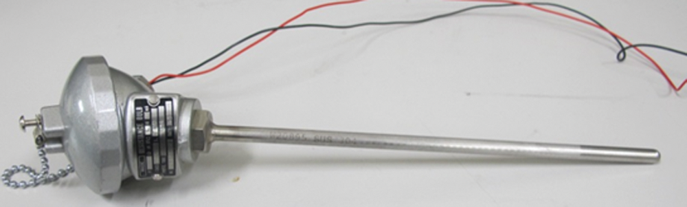
Figure 1: Platinum resistive PT100
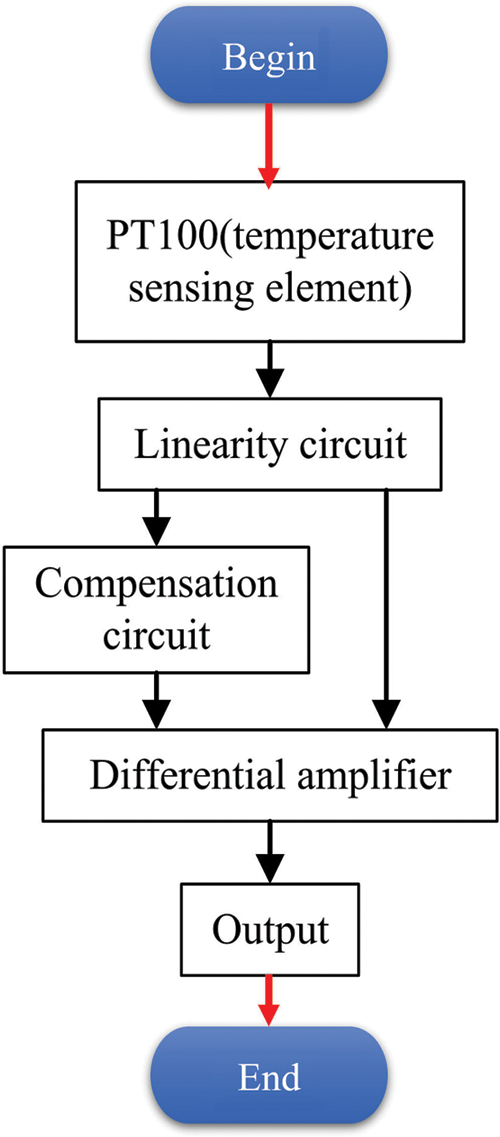
Figure 2: PT100 circuit architecture
In order to improve the condition of a fish pond temperature lower than the set temperature value, the microcontroller exports the pulse-width modulation (PWM) signal to control the solid-state relay (SSR) to adjust the heater voltage and, thus, control the heating rod temperature. Figs. 3 and 4 show the heater and its control circuit. In this paper, transmit (TX) means transmitting data, and receive (RX) means receiving data. When the fishpond temperature is higher than the set temperature value, the submerged motor pump pumps water for cooling. The microcontroller exports the PWM signal to control the SSR relay and adjust the submerged motor pump input voltage to control the motor pump output. Figs. 5 and 6 show the submerged motor pump and its control circuit.
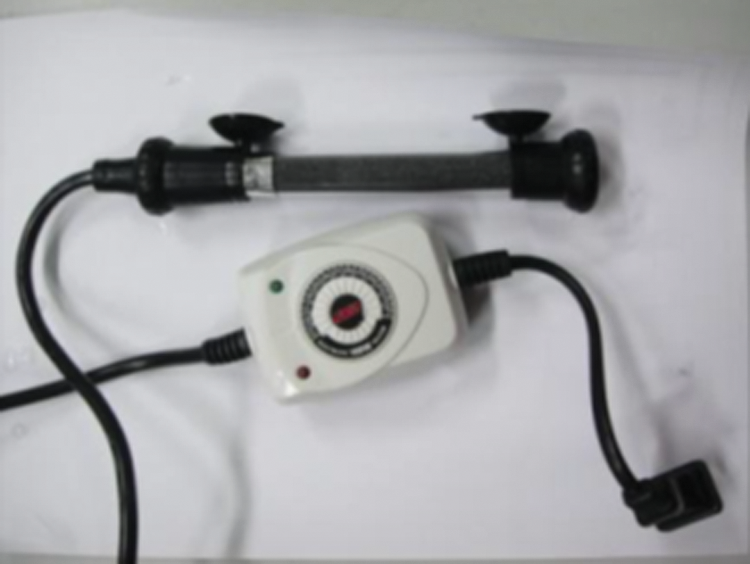
Figure 3: Heater
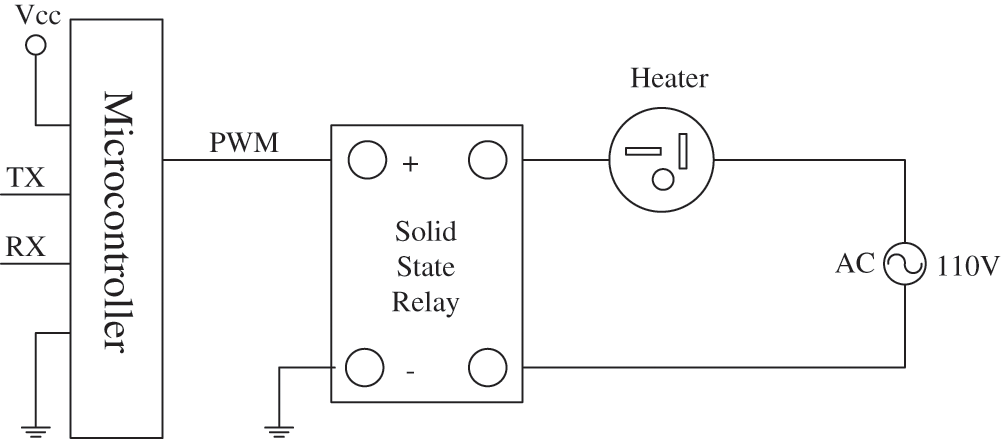
Figure 4: Heater control circuit
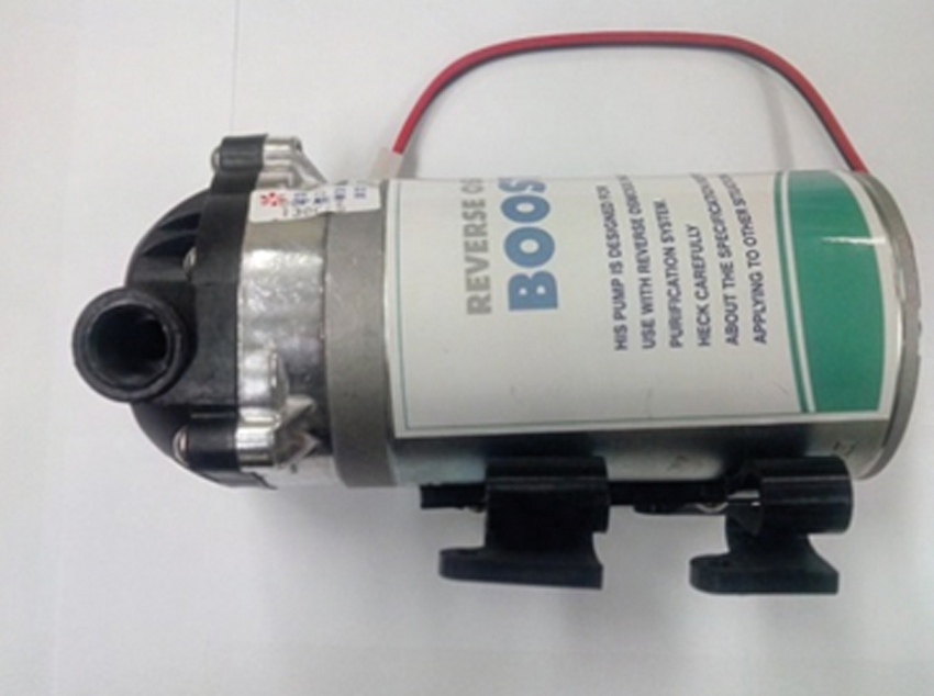
Figure 5: Submerged motor pump

Figure 6: Submerged motor pump control circuit
2.2 Liquid Oxygen Volume Sensor and Air Pump Module
In the initial stage of the development of a fish pond, there are only a few soluble minerals in the water. In particular, the concentrations of nitride and phosphate are very low, which restricts the growth of algae. Additionally, there are both liquid and solid wastes of fish. The liquid wastes are directly absorbed by aquatic plants. With the passage of time, the concentrations of nitride and phosphate in the fish pond increase, and this promotes the proliferation of algae and results in eutrophication. In this case, there will be greater demand for oxygen, and an inadequate oxygen supply will lead to the death of fish [11].
Soluble oxygen sensing measurement involves a specialized digital oxygen analyzer with a soluble oxygen measurement range of 0 to 20 mg/L, pictured in Fig. 7. The sensing data will be obtained through RS-232.
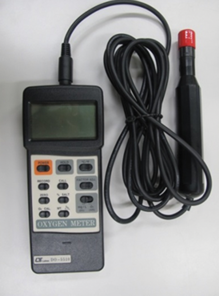
Figure 7: Soluble oxygen sensing module
When the soluble sensing module senses that the soluble oxygen volume in the water is lower than the set soluble oxygen value, the microcontroller sends PWM signals to control the SSR relay and adjust the input voltage of the air pump in order to control the motor. Figs. 8 and 9 show the air pump and its control circuit.
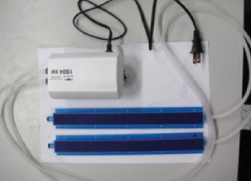
Figure 8: Air pump
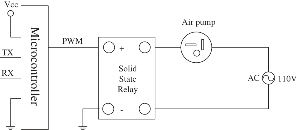
Figure 9: Air pump control circuit
In general, the pH value of water suitable for cultured fish ranges from 6 to 8. Excessively acidic or alkaline conditions are harmful to fish. Acid can erode gill organization, which can lead to coagulation necrosis, an increase in mucous secretion, hyperemia in the abdomen, and inflammation. Acid prevents proteins from changing and results in the functional loss of fish organizations and organs. Normally, a pH value lower than 4.5 will result in death. Strongly alkaline water causes gill secretions to condensate, which can cause breathing difficulties and death. To prevent such problems, a specialized digital pH value analyzer, pictured in Fig. 10, is used to monitor the water's pH value. Its measurement range is from 0 to 14, and the sensing data are obtained through RS-232.
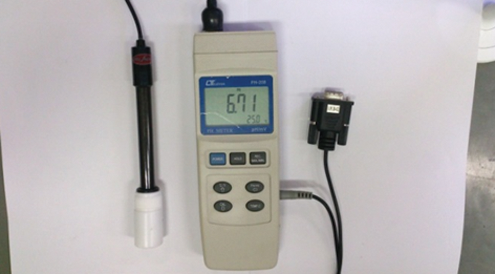
Figure 10: pH value sensing module
An automatic feed feeder can reduce labor costs by offering timed manual feeding through the software interface and control circuit. The control circuit is started when the microcontroller sends a signal to control the BS-115C relay. Figs. 11 and 12 show the feed feeder and its control circuit.
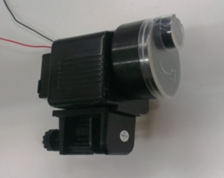
Figure 11: Feed feeder
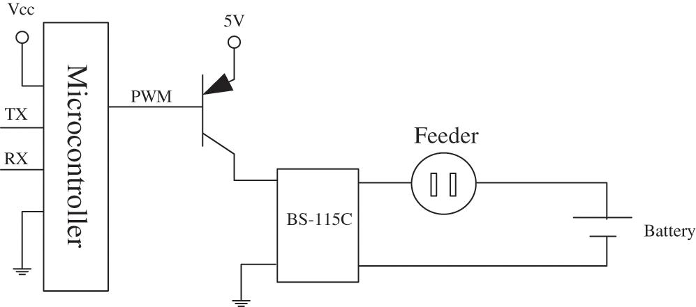
Figure 12: Control circuit of feed feeder
This study adopts ZigBee technology, which is a kind of wireless transmission technology that features low consumption rate and cost and is thus used extensively [12,13]. In the system, the star-shaped topology is adopted to establish a wireless sensing network for signal transmission. Due to the different voltage levels between the sensing signals and ZigBee signals, the sensing signals must be increased through Max232. Figs. 13 and 14 show the controlled load terminal, the sensor terminal, and the signal coordinator wireless transmission module.
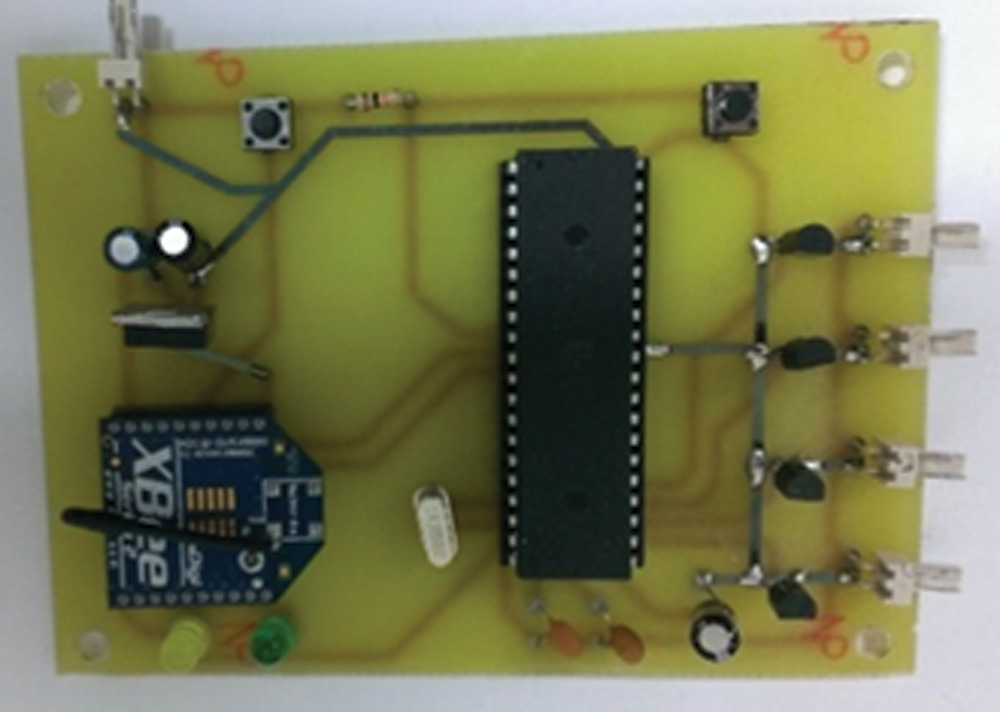
Figure 13: Wireless transmission module at the controlled terminal

Figure 14: Signal coordinator wireless transmission module
Electric supply is the most important source of power. If the electric supply becomes unreliable or there is blackout, the accumulator will serve as a temporary electric supply for the fish pond system. In general, the accumulator is charged by solar energy. In the process, solar energy is transformed into electricity to be stored in a 12 V accumulator; then, the voltage conversion module converts the electrical output from 12 to 5 V for the sensor module and control circuit. The Fig. 15 shows the electric supply conversion circuit.

Figure 15: Electric supply conversion circuit
Fig. 16 shows the system framework that imitates the fish pond culture environment in this study. In the framework, the temperature sensing module, the soluble oxygen volume sensing module, and the pH value sensing module are used to collect water quality information. The collected physical signals are sent through the wireless transmission module of the sensing terminal to the signal coordinator wireless transmission module and then to the computer. The settings, displayed and recorded temperatures, soluble oxygen volume, pH value, and feed feeder control are accessible on the human-machine interface. Moreover, fuzzy theory is used to deduce temperature and soluble oxygen sensing values, and these results are sent through the signal coordinator wireless transmission module to the wireless transmission module at the controlled terminal to control the heat, the submerged pump, and the air pump. All sensing information is uploaded onto the Internet so that mobile devices can access real-time monitoring of fish ponds via Wi-Fi. Fig. 17 shows the locations of the sensors and the controlled loads in the simulated fish pond.
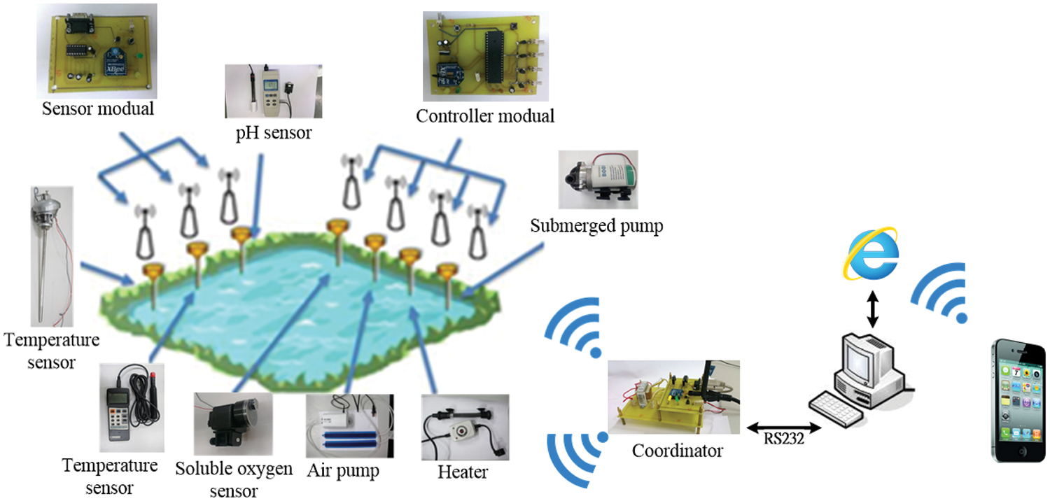
Figure 16: System framework
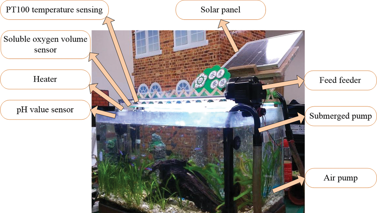
Figure 17: Locations of sensors and controlled loads
3.1 Define the Input and Output Variables
Regarding the temperature fuzzy controller, the input variables are the temperature error (E) and temperature error variable (VE), and the output variables are the heater temperature (H) and submerged pump discharge (P). Fish have changeable body temperatures and are highly sensitive to temperature, so the hourly temperature changes of the temperature controller must be confined to 4°C/h, which is the maximum temperature gap for fish [14]. Given that the variable field of the temperature error ranges from “−1” to “1”, the standardized temperature errors are [−3°C, 3°C] and [−1°C, 1°C], respectively. The field of the two output variables is [0,1].
The input variables of the soluble oxygen volume fuzzy control are soluble oxygen volume error (O) and soluble oxygen volume error variance (DO), and the output variable is air pump transmission (A). The variance set of the soluble oxygen volume errors is [−1 ppm, 1 ppm], and the variance set of the air pump transmission is [0,1].
In general, numbers are used to symbolize values, such as 180 and 160 cm for height; however, in this study, the numbers symbolizing the “value” of height are replaced by adjectives, such as “tall” and “short.” When sentences describe certain variables, they are called “sentence variables.”
3.2 Design Membership Function
The traditional clear set belongs to binary relations. Its special functions include only 0 and 1, and their values indicate a clear relationship between “belong to” and “not belong to.” The special functions of a fuzzy set can divide the extent of belonging between 0 and 1, and their values can represent the relationship between the elements and the set or the membership between the elements and the set. A higher level of membership indicates that the elements are more likely to belong to the set. Eq. (1) through Eq. (7) are membership function equations. Suppose that “A” is a clear set-in field “U” and “x” is an element in the field. Hence, the set “A” can be symbolized by a special function UA(x):
If “A” is a fuzzy set in field “U,” the membership value UA(x) is used to indicate the extent to which “x” belongs to the fuzzy set. The relationship can be shown by the following mathematical formula:
In general, membership functions can be divided into two types: the discrete membership function and the successive membership function.
Discrete membership function:
Successive membership function:
The triangular membership function, trapezoid membership function, and Gaussian membership function, presented by Figs. 18–20, respectively, are the typical and frequently used successive membership functions.
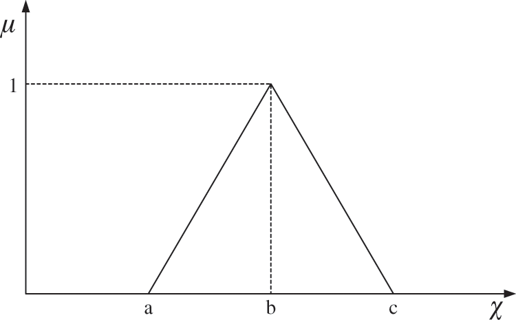
Figure 18: Triangular membership function
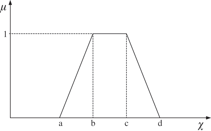
Figure 19: Trapezoid membership function
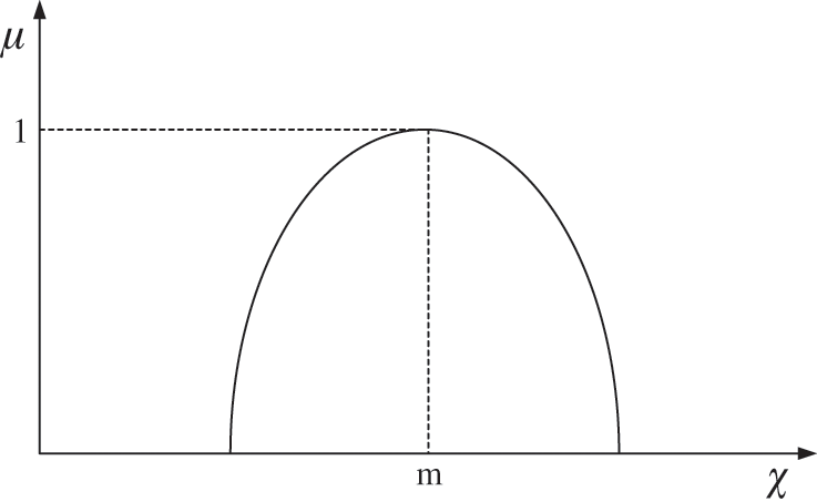
Figure 20: Gaussian membership function
3.2.1 Triangular Membership Function and Graph
3.2.2 Trapezoid Membership Function and Graph
3.2.3 Gaussian Membership Function and Graph
In this study, the triangular membership function is adopted for the fuzzy membership functions of the input and output variables of the temperature fuzzy controller and the soluble oxygen volume fuzzy controller in order to facilitate the processing and calculation of digital signals. Fig. 21 shows the membership functions of the variables.
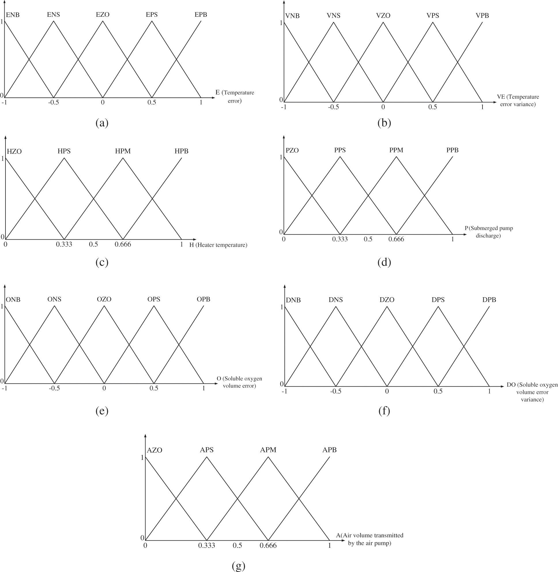
Figure 21: Membership functions of input and output variables (a) Temperature error membership function (b) Temperature error variance membership function (c) Heater temperature membership function (d) Submerged pump discharge membership function (e) Soluble oxygen volume error membership function (f) Membership function of soluble oxygen volume error variance (g) Membership function of air volume transmitted by the air pump
3.3 Establish the Fuzzy Rule Database
The fuzzy deduction rule database designed in this study provides behavior rules for the control system. In other words, the designer summarizes practical experience into conditional sentences to describe the relationships between input and output variables, which creates rational control over the controlled variables according to the fuzzy rule database [15].
Fuzzy rules can be divided into three types, namely, semantic fuzzy rules, functional fuzzy rules, and Tsukamoto fuzzy rules [16]. In this study, semantic fuzzy rules, also called Mamdani fuzzy rules, are adopted. The typical semantic fuzzy rules are as follows:
Both the temperature fuzzy controller and the soluble oxygen volume fuzzy controller have two input variables. Each input variable is differentiated by five sentences, which leads to 25 rules. According to the semantic fuzzy rules and adjustments after the experiment, two databases are established. Tab. 1 shows the temperature fuzzy rule database, and Tab. 2 shows the soluble oxygen volume rule database.


Fuzzy inference factors refer to a fuzzy rule database, which consists of some inference sentences featuring “if…, then….” When an “input” enters the rule database, there will be an output after some calculation. Combinations of different representation and integration methods of inference sentences with different fuzzy logic inference are used to generate various inference factors. Common representation methods of inference sentences include the Dienes–Rescher representation method, the Lukasiewicz representation method, the Zadeh representation method, the Godel representation method, the Mamdani minimum representation method, and the Mamdani product representation method. In this study, the Mamdani minimum representation method [17] is adopted, and it is illustrated as follows:
• If FP1, then FP2 can be represented as FP1 − > FP2
•
• Mamdani minimum representation method: FP1 − >FP2 = min(FP1(x), FP2(y)) ≜ RMM(x, y)
• FP1(E, VE) → FP2(H) = min(FP1(E, VE), FP2(y)) ≜ RMM((E, VE), H)
The Eqs. (8)–(11) are fuzzy inference factor equations. In the integrated rule database, the methods for several fuzzy inference sentences include “Mamdani integration” and “Godel integration.” In this study, Mamdani integration is adopted, and the results are as follows (“Q” in the following formula represents “m” (cardinal number) rules R(n)):
Generalized modus ponens (GMP) is used in fuzzy logic inference, which can be seen as a system. As shown in Fig. 22, input is Prerequisite 1, factor is Prerequisite 2, and output is Conclusion in GMP.
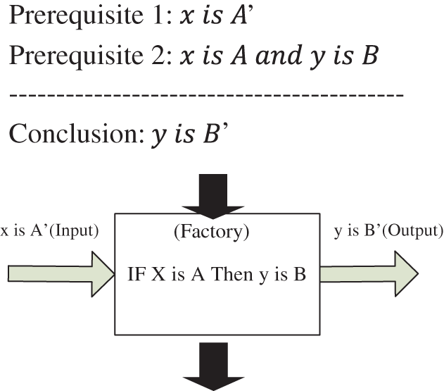
Figure 22: Generalized modus ponens
To reduce the burden of calculation of the Mamdani minimum representation method, Mamdani integration and GMP are adopted to obtain the output. Such a combination is called the smallest inference factor, as shown in the following formula:
The purpose of defuzzification is to clarify the inference results of fuzzy inference factors by converting fuzzy set B′(y), y ∈ Y, into an action with a clear value. In other words, it aims to seek a clear point B′(y) that can best represent fuzzy set
Successive algorithm:
Discrete algorithm:
With the Fuzzy module in the simulation software MATLAB, this study establishes a temperature fuzzy controller and a soluble oxygen volume fuzzy controller. As shown in Fig. 23, the temperature fuzzy controller and the soluble oxygen volume fuzzy controller set the fuzzy intersection as the standard intersection “min,” while the fuzzy united set sets the standard united set “max” through the editing interface; the inference representation method is the “Mamdani minimum representation method”; the inference sentence integration is the “Mamdani integration”; and the defuzzification method is the core defuzzification method. The configuration of the curves is achieved with the established fuzzy rule database and membership function, where each curve displays the output variance derived from the two inputs. To enhance the adaptability of the system, the curves are analyzed to modify the fuzzy rule database and membership function. Fig. 24 displays the curves of the three output variables.
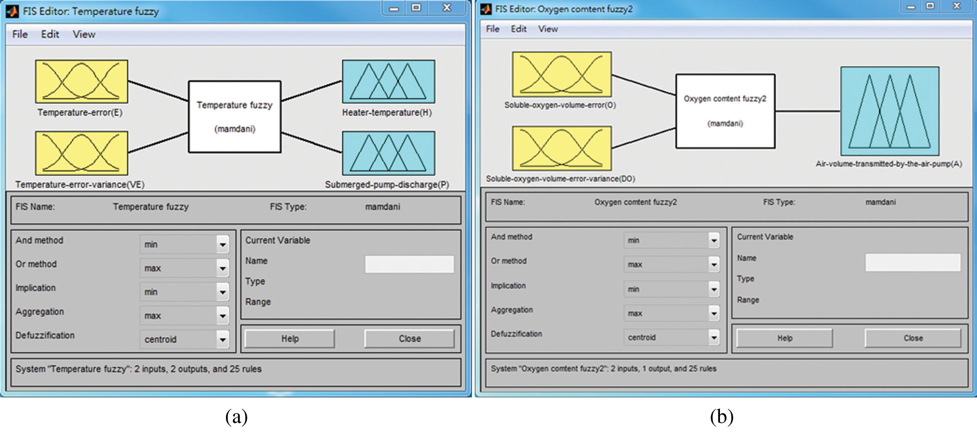
Figure 23: Editing interface of fuzzy controller (a) Editing interface of temperature fuzzy controller (b) Editing interface of soluble oxygen volume fuzzy controller
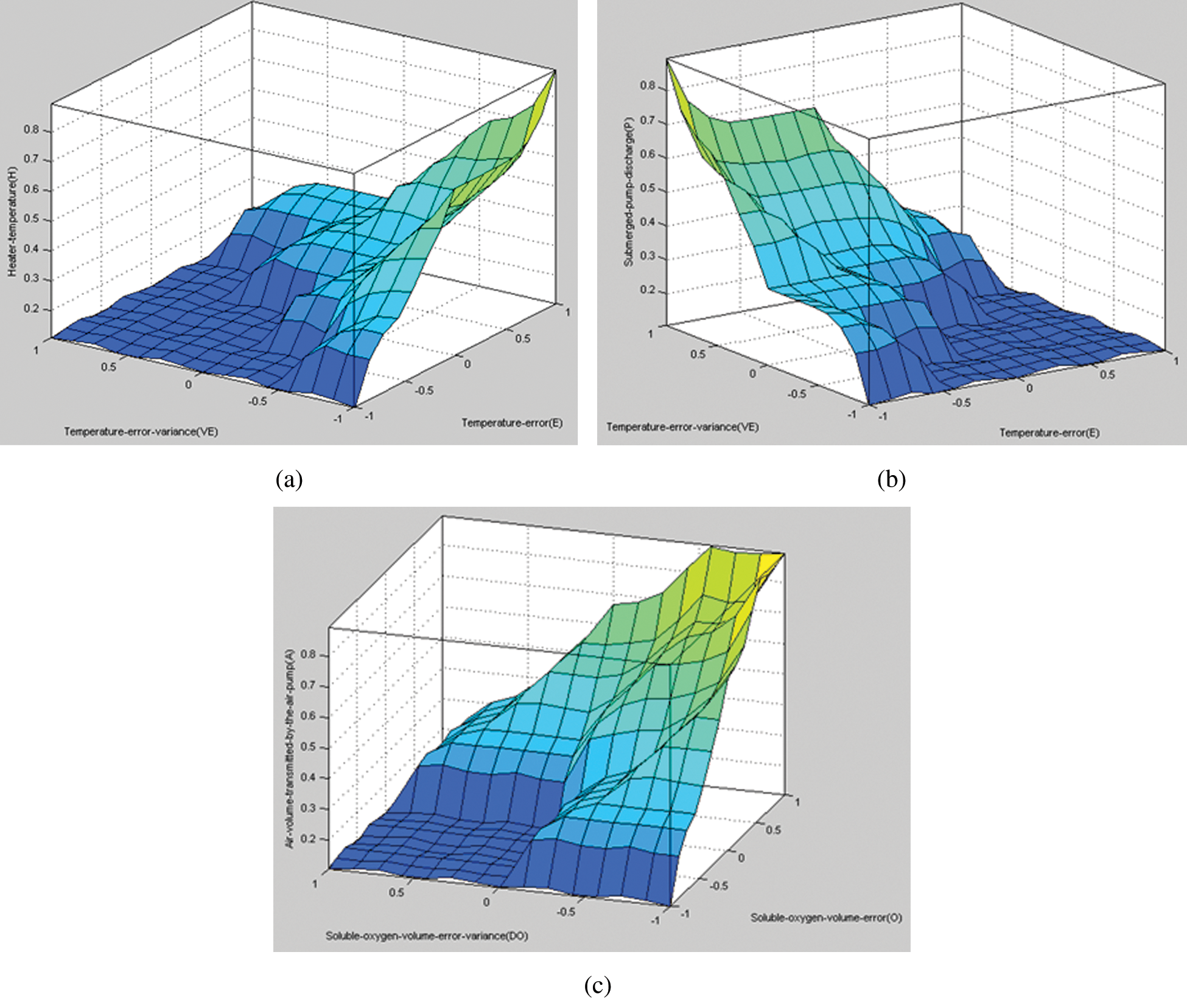
Figure 24: The curves of the three output variables (a) Curve of the heater temperature (b) Curve of the submerged pump discharge (c) Curve of the air volume transmitted by the air pump
The human-machine interface of the wireless monitoring system in this study is designed with the graphical window program Visual Basic.
The monitoring interface mainly displays temperature, soluble oxygen volume, and the actual curve graphs measured by the pH sensing module. Meanwhile, scroll settings are used to meet the demand of users in the environment. First, the values measured by the sensor are compared with the set values. Next, the errors and error variance are taken as the input of the fuzzy logic controller. After fuzzification and defuzzification, the output control signals determine the operation of controlled loads. For instance, when the temperature error is within the range [−1°C, 1°C], the situation will be normal. If the actual values are lower than the set values, the control rules obtained from the fuzzy controller will lead to the low-power operation of the heater, resulting in a stable rising temperature curve; on the contrary, if the actual values are higher than the set values, the heater will stop operating to facilitate low-rated operation, and the water temperature will decline due to water recycling. When the temperature error is outside the range [−1°C, 1°C] and there is an excessively high or low temperature, there will a high-rated operation or operation suspension of the output of the fuzzy controller. Under every situation, the fuzzy controller will constantly adjust the heater to control the heater temperature and the submerged pump discharge until the error equates to zero. This Visual Basic program is used to design the window pages of the interface, including the environment-monitoring page, the abnormal record page, and the feed control page, which are shown in Fig. 25. In the control interface of the feeder, the feeder can be manually opened or the time of opening can be set. Fig. 26 shows the feeding control interface.
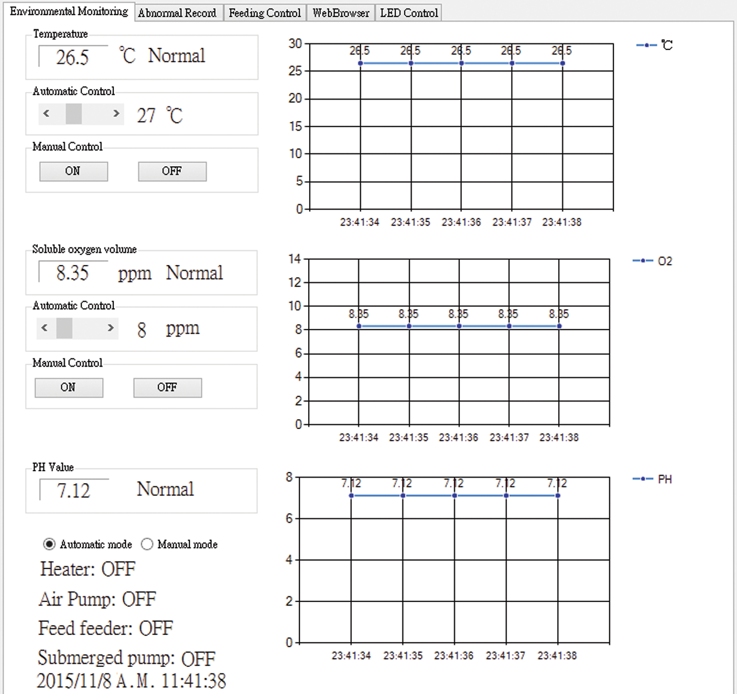
Figure 25: Environment-monitoring page
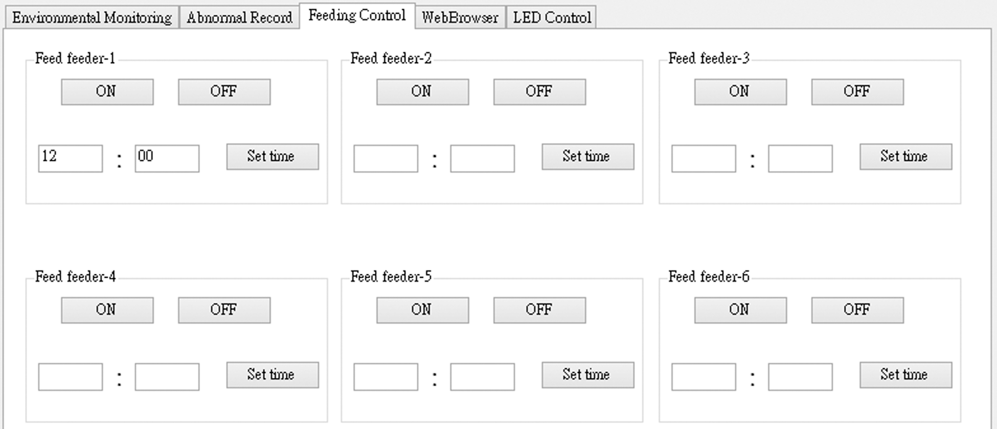
Figure 26: Feeding control page
Webpage users can monitor water quality and the on/off situation of controlled loads with mobile devices. Through actual measurements and experimentation, this study compares the traditional on/off control with fuzzy control. The traditional on/off control functions by merely judging if the temperature and soluble oxygen volume are higher or lower than the set values, and the heating rod, submerged pump, and air pump operate with rated power.
In contrast, the fuzzy controller controls the operational power according to the results of inference. Figs. 27 and 28 are the curve graphs of water temperature and soluble oxygen volume, which are renewed every ten seconds. According to the curve graph of the fuzzy control, though fuzzy control results in smaller errors, it is more stable than the tradition on/off control; moreover, its water temperature error percentage is lower than 1.2%, and its soluble oxygen volume error percentage is lower than 2.5%. T1 is the water temperature response curve of the traditional on/off control; T2 is the water temperature setting curve; and T3 is the water temperature response curve of the fuzzy control. O1 is the soluble oxygen volume response curve of the traditional on/off control; O2 is the soluble oxygen volume setting curve; and O3 is the soluble oxygen volume response curve of the fuzzy control.

Figure 27: Water temperature vs. time. of the fuzzy control
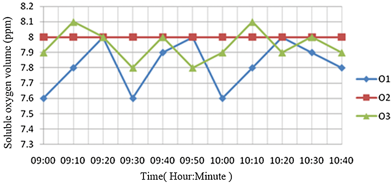
Figure 28: Soluble oxygen vs. time
This study proposes the use of wireless sensor network architecture to build a highly efficient fish pond aquaculture monitoring system. This system uses fuzzy algorithms to control hardware devices that adjust multiple variables of the environment. Therefore, accurate sensing data and correct control are key characteristics of this system. To enhance culture efficiency in fisheries and improve traditional control, this study takes the fuzzy controller as the control core of the system and uses a wireless sensing network framework to establish a simulated automatic monitoring system based on an actual fish pond culture environment. In terms of signal transmission, the ZigBee wireless technology replaces wired transmission. In addition to solving the difficulties of wire layout and reducing hardware costs, the network topological hardware structures contribute to wider transmission coverage. In this study, the most important part of hardware control is the design of the fuzzy controller. After the errors in the water quality variables and the error variances are fuzzified and inferred by fuzzy factors, they are defuzzified to output results to control loads. According to the curve graphs, which are based on actual measurements, it can be clearly seen that there is significant error between the fuzzy controller and the traditional controller and that the former renders the system more stable. Therefore, the fish pond aquaculture monitoring system proposed in this study is feasible, and it can provide a more stable and suitable growth environment for aquatic creatures.
Acknowledgement: This research was supported by the Department of Electrical Engineering at National Chin-Yi University of Technology. The authors would like to thank the National Chin-Yi University of Technology, Takming University of Science and Technology, Taiwan, for supporting this research. We thank LetPub (https://www.letpub.com) for its linguistic assistance during the preparation of this manuscript.
Funding Statement: The authors received no specific funding for this study.
Conflicts of Interest: The authors declare that they have no conflicts of interest to report regarding the present study.
Availability of data and materials: Data sharing not applicable to this article as no datasets were generated or analyzed during the current study.
1. W. Wang and S. Cao, “Application research on remote intelligent monitoring system of greenhouse based on zigbee wsn,” in 2009 2nd International Congress on Image and Signal Processing, pp. 1–5, Tianjin, China, 2009. [Google Scholar]
2. Z. Zou, D. Han, X. Gui, D. Zhao, Y. Guo et al., “Fuzzy auto-tuning PID control of a small electric-heating reactor,” in 2011 2nd Int. Conf. on Intelligent Control and Information Processing, vol. 2, pp. 1045–1050, Harbin, China, 2011. [Google Scholar]
3. A. B. Patil and S. Amit, “Adaptive neuro fuzzy controller for process control system,” in 2008 IEEE Region 10 and the Third Int. Conf. on Industrial and Information, pp. 1–5, Kharagpur, India, 2008. [Google Scholar]
4. T. F. Li, C. Y. Liu, Z. Y. Song, X. L. Song and Q. Q. Yan, “Application of ANFIS in the design of fuzzy controller,” in 2012 Int. Conf. on Machine Learning and Cybernetics, vol. 3, pp. 825–829, Xian, China, 2012. [Google Scholar]
5. P. V. S. Reddy, “Some methods of fuzzy conditional inference and fuzzy reasoning,” in 2013 Int. Conf. on Fuzzy Theory and Its Applications (iFUZZYpp. 61–64, Taipei, Taiwan, 2013. [Google Scholar]
6. M. Garcia, S. Sendra, G. Lloret and J. Lloret, “Monitoring and control sensor system for fish feeding in marine fish farms,” IET Communications, vol. 5, no. 12, pp. 1682–1690, 2011. [Google Scholar]
7. W. T. Sung, J. H. Chen and S. J. Hsiao, “Fish pond culture via fuzzy and self-adaptive data fusion application,” in 2017 IEEE Int. Conf. on Systems, Man, and Cybernetics (SMCCanada, 2017. [Google Scholar]
8. J. Jimsan, B. Surarso and S. Suryono, “Monitoring of pond water quality using fog network with fuzzy rule based algorithm,” in 2019 Fourth Int. Conf. on Informatics and Computing (ICICIndonesia, 2019. [Google Scholar]
9. J. V. Magsumbol, V. J. Almero, M. Rosales, A. A. Bandala and E. P. Dadios, “A fuzzy logic approach for fish growth assessment,” in 2019 IEEE 11th Int. Conf. on Humanoid, Nanotechnology, Information Technology, Communication and Control, Environment, and Management (HNICEMPhilippines, 2019. [Google Scholar]
10. S. Lauguico, R. Baldovino, R. Concepcion, J. Alejandrino, R. R. Tobias, et al., “Adaptive neuro-fuzzy inference system on aquaphotomics development for aquaponic water nutrient assessments and analyses,” in 2020 12th Int. Conf. on Information Technology and Electrical Engineering (ICITEEIndonesia, 2020. [Google Scholar]
11. R. Chen, F. Formenti, H. McPeak, A. N. Obeid, C. E. W. Hahn et al., “Optimizing design for polymer fiber optic oxygen sensors,” IEEE Sensors Journal, vol. 14, no. 10, pp. 3358–3364, 2014. [Google Scholar]
12. D. M. Han and J. H. Lim, “Design and implementation of smart home energy management systems based on zigbee,” IEEE Transaction Consumer Electron, vol. 56, no. 3, pp. 1417–1425, 2010. [Google Scholar]
13. C. Zhang and W. Luo, “Topology performance analysis of zigbee network in the smart home environment,” in 2013 5th Int. Conf. on Intelligent Human-Machine Systems and Cybernetics, vol. 2, pp. 437–440, Hangzhou, China, 2018. [Google Scholar]
14. C. Shuai, Z. Ke and C. Yingling, “The design and application of the water temperature control system for large aquaculture pond,” in 2011 Third Int. Conf. on Measuring Technology and Mechatronics Automation, vol. 3, pp. 737–739, Shanghai, China, 2011. [Google Scholar]
15. R. Zhou, J. Feng, Y. Chen, H. Chang and Y. Zhou, “Representation and reasoning of fuzzy knowledge under variable fuzzy criterion using extended fuzzy petri nets,” IEEE Transactions on Fuzzy Systems, vol. 28, no. 12, pp. 3376–3390, 2020. [Google Scholar]
16. P. N. Darma and M. Takei, “High-speed and accurate meat composition imaging by mechanically-flexible electrical impedance tomography with k-nearest neighbor and fuzzy k-means machine learning approaches,” IEEE Access, vol. 9, pp. 38792–38801, 2021. [Google Scholar]
17. M. Adnan, L. Yang, T. Ahmad and Y. Tao, “An unequally clustered multi-hop routing protocol based on fuzzy logic for wireless sensor networks,” IEEE Access, vol. 9, pp. 38531–38545, 2021. [Google Scholar]
 | This work is licensed under a Creative Commons Attribution 4.0 International License, which permits unrestricted use, distribution, and reproduction in any medium, provided the original work is properly cited. |