DOI:10.32604/iasc.2022.019493
| Intelligent Automation & Soft Computing DOI:10.32604/iasc.2022.019493 | |
| Article |
An Efficient HAPS Cross-Layer Design to Mitigate COVID-19 Consequences
Department of Computer Engineering, College of Computers and Information Technology, Taif University, P.O. Box 11099, Taif 21944, Saudi Arabia
*Corresponding Author: Sameer Alsharif. Email: s.alshareef@tu.edu.sa
Received: 15 April 2021; Accepted: 27 May 2021
Abstract: This paper proposes a new cross-layer communication system for the provision of Internet services and applications to mitigate the negative impacts of COVID-19, due to which the massive online demands are affecting the current communication systems’ infrastructures and capabilities. The system requirements and model are investigated where it utilizes high-altitude platform (HAP) for fast and efficient connectivity provision to bridge the communication infrastructure gap in the current pandemic. The HAP is linked to the main server or gateway station located on ground and can provide communication narrow beams towards isolated areas which suffer from poor terrestrial radio coverage or lack of communication infrastructure. The vital e-learning applications using Internet services provision from the proposed HAP system are described and modelled including system adaptation parameters such as the application and physical layers to control the data rates of different e-learning applications and the overall cell data rate. On the other hand, the provision of high-speed Internet services from the proposed system is supported by using adaptive antenna arrays onboard HAP which provides high-gain beams to achieve the required high-quality transmission data rates at the student premises and provides the capability of coverage cell area adaptation for load balancing. The concentric circular antenna arrays with tapered feeding are proposed in this adaptive antenna system to control the cell mainlobe gain and reduce the out-of-coverage radiation as well. In addition, the system feasibility has been proved in two coverage scenarios including single-beam and multibeam HAP communications.
Keywords: COVID-19; cross-layer; high-altitude platforms; adaptive arrays
Virus outbreaks seriously affect all aspects of life and lead to increasing infection and toll rates. COVID-19 has a very high infection rate, and it has spread to almost all the territories of the world [1–3]. Unfortunately, this virus is genetically variant and may last for a few years. Governments and health organizations recommend quarantine and increased social distance to reduce the infection rate and mitigate the other consequences. The quarantine means that we should rely mainly on online services and that these should be provided to as many people as possible worldwide. Many services such as e-commerce and e-learning services are used extensively and require a supporting communication network infrastructure as many employees, trainees, and students work from home [4,5].
Despite the high demand on the Internet during this pandemic, some regions in some countries suffer from weak or even a lack of communication network infrastructure, and this affects the countries’ capability to support their population with e-services such as e-learning. Deploying terrestrial networks for these regions within a short period of time is impossible or requires very costly infrastructure. Therefore, governments can utilize satellite systems to provide extensive coverage instead [6]. However, the considerable distance from which satellites operate and the special terrestrial transceivers and installation requirements are barriers to the use of such systems. Besides, satellite systems provide low data rates, which may not suit the current package of Internet services that is used to meet people’s requirements [7].
Another difficulty in Internet provision through satellites is the high rates of service provision, which is not suitable for the current economic situation. Therefore, a new communication system infrastructure should provide compatible, high-speed Internet at a low cost. Alternatively, high-altitude platforms (HAPs) can be employed to provide superior, comprehensive coverage and high-quality communication performance [8]. HAPs are airborne balloons, airships, or unmanned aircraft that operate in the stratosphere; these can provide coverage to an area of up to 1000 km in diameter and have a communication channel performance like that of satellite systems but at very low relative altitudes.
Students in remote rural areas that suffer from a lack of communication services or inadequate cellular coverage and minimal Internet rates are unable to continue their distance or e-learning. Flying airborne systems and moving them to such inaccessible areas will provide instant wireless communication infrastructure, thereby relieving students [9]. In this paper, we consider a HAP to provide an efficient solution for the rapid establishment of the communication network to help students access e-learning services remotely [10]. The development of efficient antenna techniques at the HAP will improve data rate provision to support Internet services and the number of users.
The main objective of this paper is to solve the problem of Internet service provision in remote areas with undeveloped communication infrastructure and those where such infrastructure is impossible to develop. Therefore, we propose and analyze a new end-to-end model for the emergency and fast deployment of a communication system using a novel cross-layer between the adaptive antenna, MAC layer, and application layer; the system’s mathematical and geometrical models are also investigated along with the practical applicability and feasibility of the system.
The paper is arranged as follows: Section 2 discusses the related cross-layer optimization techniques for the current systems and HAPs. It also details the current e-learning systems and their requirements, while Section 3 introduces the proposed HAP e-learning system model. In Section 4, we demonstrate the adaptive cellular e-learning HAP system using adaptive antenna arrays onboard HAP. Section 5 explores the role of adaptive antenna arrays in coverage cells’ formation and adaptation. Section 6 presents the communication performance evaluation, and finally, Section 7 concludes the paper.
Cross-layer design is one of the most interesting end-to-end system models, and it is extensively discussed in the literature. It is a set of methodologies for manipulating various parameters across the network layers, from the physical to the application layers. The proposed e-learning solution for Internet services provisioning over HAP considers an end-to-end model that addresses all network layers. Therefore, here we review the related works that focus mainly on the cross-layer models and address models that associate adaptive antenna and MAC and application layers for multi-users. For instance, an author [11] designed a sub-optimal power control for the physical layer of uplink multiple-antenna non-orthogonal multiple access (NOMA) model to improve the overall data rates. The proposed method’s complexity was tested, and it was found that it is slightly better than that of the physical layer method [12]. A study [13] proposed a cloud radio access network (C-RAN) to enhance the strides range and vitality effectiveness of remote systems through the relocation of routinely disseminated BS capabilities into a centralized cloud baseband unit (BBU) pool. Another paper [14] proposed a cross-layer cooperative beamforming system with an ideal weight plan. The paper proposed two imperfect weight plans for multibeam beamforming to choose the weights that maximize ghostly productivity.
Another author [15] discussed a cross-layer design method for cross resource allocation and routing for the physical (PHY) and MAC layers in multi-hop wireless backbone communications. They furnished the base stations (BSs) with a smart antenna that could receive and transmit adaptive beams. A nonlinear optimization model was derived, which improved the throughput of the BSs under the PHY/MAC and routing assumptions, and the results verified the effectiveness of the proposed cross-layer model.
Another work [16] suggested a superimposed pilot (SiP) sequence-based channel estimation strategy for beamforming to help multi-antenna HAP arrive versatile radio communication frameworks [17,18]. The proposed strategy misused the initially accessible data of users’ spatial area and thickness and a beamwidth of HAP directional receiving wire. Particularly, the author proposed area data-supported and low power control SiP sequence-based stagewise orthogonal match pursuit (StOMP) calculation to estimate channels, from single-antenna client terminals to beamforming, to help expansive-scale multiple-antenna HAP [19].
Another study [20] proposed a modern cross-layer method that included a concurrent shrewd smart antenna at the physical layer and arbitrary network coding at the network layer to enhance the overall network’s performance. The simulation results showed the effectiveness of the proposed method. Some researchers [21] investigated the long-term renewable smart energy-disbursement reduction issue and expressed it as a stochastic optimization scheme. Simulation results showed that the proposed successive approximation smart antenna (SABF) [22] scheme outperforms the zero-forcing smart antenna scheme (ZFBF) [23] in both smart grid disbursement and packet loss. The smart grid disbursement enhanced the packet loss under the proposed model by altering a control coefficient.
Other researchers [24] evaluated the performance of dynamic minimum variance distortionless response (MVDR) and least squares (LS) smart antenna on the downlink (DL) channel from HAP to high mobility train. They assumed that the channel was flat-fading and time-varying Rician (TVR). The dynamic MVDR smart antenna is more effective for the Rician fading channel. The results verified that by developing the LS smart antenna, the receiver can dynamically cope better than the Rayleigh fading channel.
The rapid advancement of distance learning (DL) technologies has created more chances to bail out the educational systems affected by the pandemic. Indeed, communication technologies help web-based DL thrive and grant fair educational opportunities to a large population of students [25]. As a consequence of these innovations and other web development, universities and schools started using web-based DL platforms to provide flexible education regardless of temporal and spatial differences. Besides, the technical advancement in learning management systems (LMSs), such as Moodle, Blackboard, Claroline, ATutor, Desire2Learn (D2L), Dokeos, OLAT, eFront, etc., is the driving force for the modern implementation strategies. Moodle and Blackboard are the two most recognized web-based LMSs that are progressively used as platforms in general and higher education. With different types of DL in concept, practice, and experience, these platforms are advancing rapidly to deliver a comfortable educational system [26].
Although Internet penetration is expected to surpass 50 percent of the world population by the end of 2020, more considerable broadband penetration and telecommunications services are needed for impoverished people and remote rural areas. Due to adequate infrastructures, distance education and e-exam can be affordable in metropolises and cities. However, the currently available broadband access technologies are still not mature enough in remote regions. Qualified rural broadband applications at minimal cost are required to increase Internet accessibility. This can be achieved through the wide spectrum of accessible and scalable wireless technologies [27]. Therefore, the traditional DL system essentially requires a highly secure wireless communication platform with affordable prices. Such a platform has certain criteria such as two-way communications, real-time video streaming, file sharing, and deliberations [28]. Broadband access should involve efficient, cost-effective, and fast-deployment technologies to improve accessibility. Economic and technological considerations are the critical challenges of delivering broadband networks in remote areas [29]. For instance, the configuration of fiber optic backhauls connectivity or 4G deployment in rural counties remains an expensive option. Network operators should develop a new broadband wireless access technology to overcome the mentioned challenges. The new technology possesses the following properties: (1) visible enough to operate with low power; (2) have low provisioning cost; (3) be a rigid type of climate; (4) have fading channels technology. Although the researchers have already extensively investigated this subject, such challenges still need to be considered with regard to e-learning in remote territories. These challenges range from the physical to the network layers and include the quality of the services for real-time, delay-sensitive applications, offline storage spaces, recording, and data retrieval.
Wireless HAP communication is an alternative compromising solution for supplying DL [30]. Network operators can utilize HAP systems to provide fixed broadband connectivity to end-users in remote areas, which include mountainous, coastal, and desert areas. HAP needs lower venture and operation costs to a certain extent and provides high-quality services and enough capacity for e-learning. In pandemic situations like the COVID-19 one, HAP can be rapidly deployed for DL because it allows for the establishment of services with minimal ground network infrastructure. HAP can also easily be reallocated to different locations at minimum cost [31].
4 Adaptive E-Learning Provision from HAPS
Fig. 1a shows e-learning services provision from HAP by adaptive antenna arrays system onboard HAP fed by the coverage information from the university site’s ground station. The beamforming information is defined according to the registered report of the students on the university e-learning database—such as home locations, academic schedule, the number of students in a common remote region, the minimum services bit rate, etc. This information is extracted at the HAP beamformer input to direct suitable beams for students’ locations. The HAP acts as a repeater in this case and can be considered as a fixed “stratospheric satellite” [32].
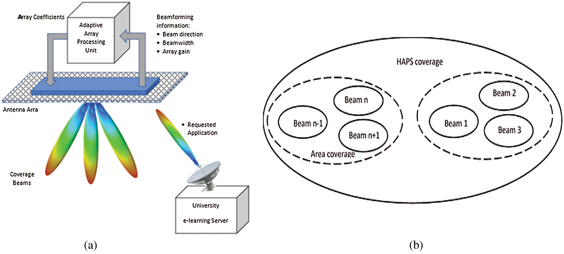
Figure 1: Adaptive antenna array onboard HAP: (a) System architecture for e-learning services provision (b) Modelling of physical distribution of HAP coverage beams
The beamforming can be done through many suitable planner antenna structures, such as two-dimensional or concentric arrays. This paper focuses on concentric arrays due to their performance superiority and azimuth-independent beam-generation property. The taper profile function feeds the array to improve the sidelobe performance and reduce the co-channel interference if frequency reuse is applied.
Fig. 1b shows the distribution for HAP coverage cells. The system splits the coverage into area coverage (residential area) and antenna spot beams within the residential area. We assume that we have N residential areas, M spot beams, and P applications and services within each beam. The proposed model for managing applications is based on socket and port numbers, and the network administrator identifies the privilege for each application. The beam data rate is Cm, while the network operation center (NOC) data rate is CT. The beams and the associated data rates are distributed based on users’ activities and application priorities.
The system starts by allocating the total data rate (CT) at NOC, applying policies and limitations, and calculates the antenna array feeding currents required to form a coverage beam. Then, it receives the requester’s order and verifies that the beam covers it. If the requester is out of beam coverage, the system forms a new beam and allocates resources to the MAC. Then, it calculates the data rate in the formed beam to allocate more resources to it. Once the beam array is created with the corresponding data rate and the resources are assigned, the system checks whether the requested application is open. If the application is open, the system applies for limitation roles, receives more applications, and checks their types. It gives the best allowed resources to the application within the schedule, and then it is ready to welcome new requests. But if the application is not in the plan, it verifies if the application is permitted to give the best-effort resources. If it is not, it should be blocked. If the application is originally not open, the program calls the application layer for data rate adaptation. The flowchart of this plan is shown in Fig. 2.
4.2 System Adaptation Parameters
This section demonstrates and discusses the system adaptation parameters for HAP e-learning services. These parameters include the operation on both the application and physical layers to control the data rates of different e-learning applications and the overall cell data rate. Eq. (1) shows the total NOC link capacity:
where
where
Proportional utilization coefficient,
Then, the total data rate designated for the i area with multiple beams,
which can also be expressed as
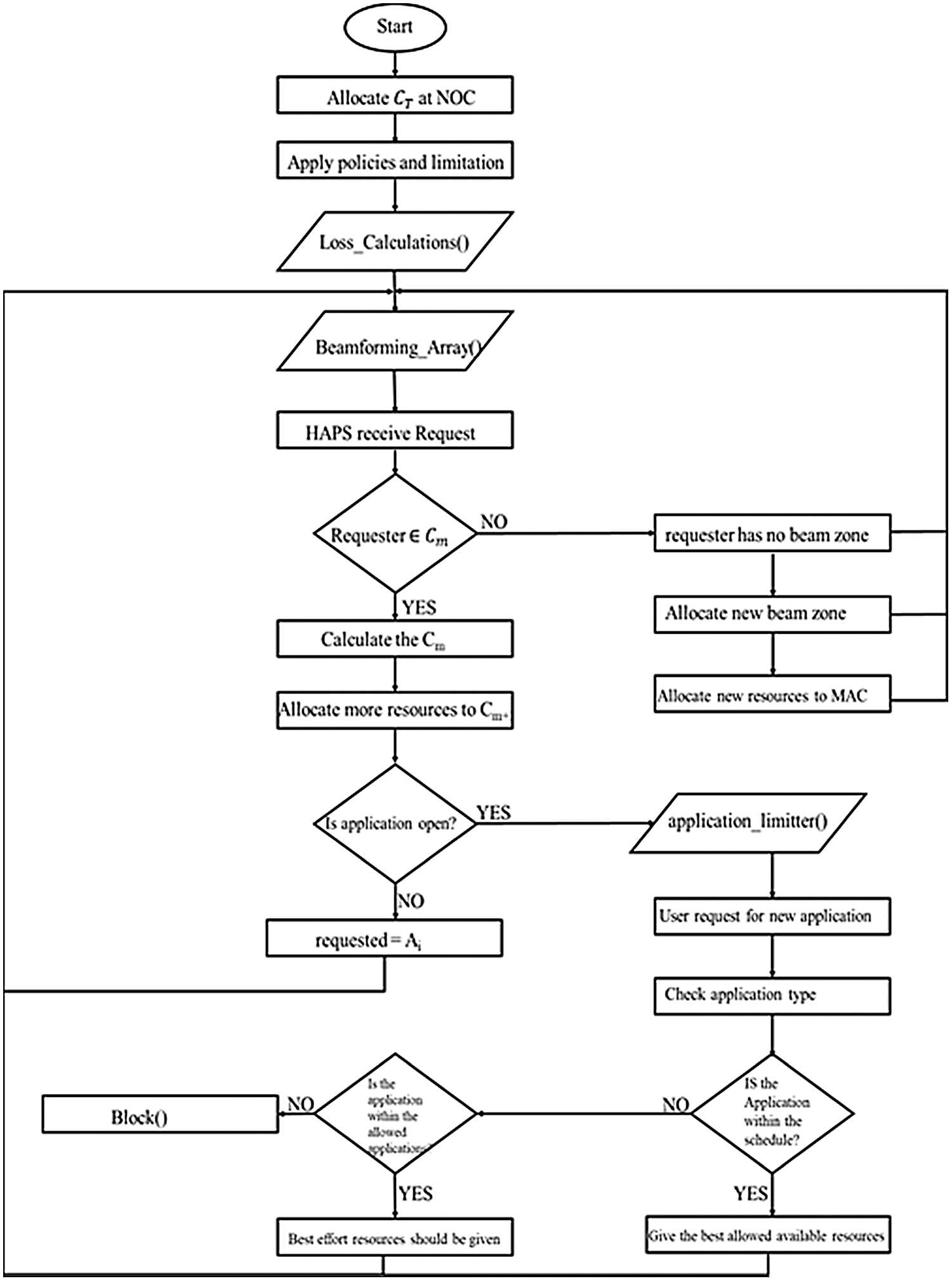
Figure 2: The algorithm of resources distribution in HAPS
The NOC can dedicate
To find the data rate for each student in the same area for a specific service such as e-learning, we divide
Eventually, we express the application layer data rate adaptation parameter for the ith beam,
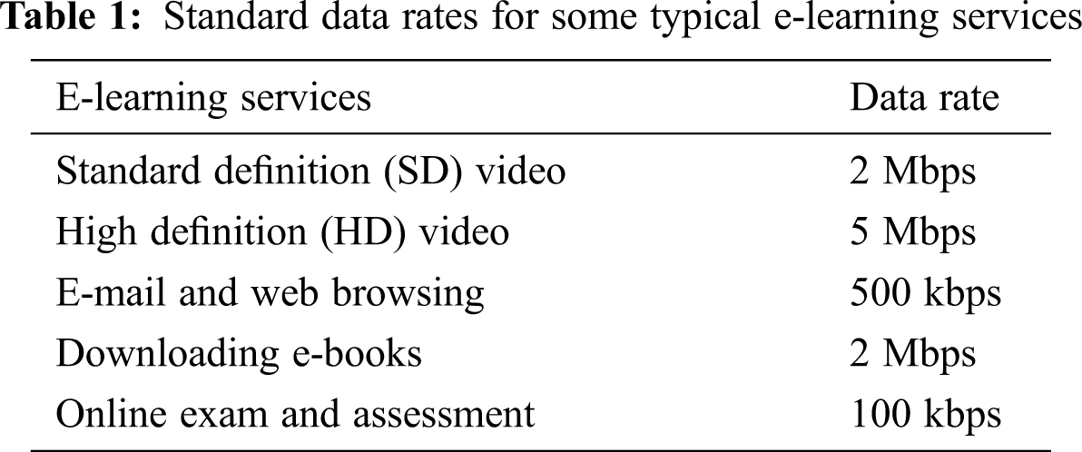
This scheme is compared with some typical e-learning services in terms of data rates in Tab. 1.
The other physical-layer adaptation factor for
5 HAP Cell Coverage Adaptation Using Onboard Antenna Arrays
This section demonstrates the physical coverage cells’ formation and adaptation. First, it illustrates the coverage area and cell geometry and shows the controlling parameters. Second, it shows how to link the coverage cell area with the HAP antenna array system to achieve the required adaptation process.
5.1 HAP Coverage Cell Formation and Control
We can address the problem of delivering local e-learning services by incorporating the e-learning management system into the communication facility to bridge the information gap in distant or isolated regions. Consider a HAP station located at an altitude of h km in the stratosphere, as shown in Fig. 3. The maximum coverage diameter can be obtained by the following equation:
where
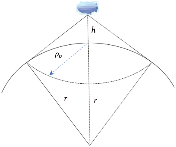
Figure 3: Maximum HAP coverage area and radius
Some beaming techniques, such as directional spot-beam antennas or antenna arrays, provide service beam from HAP. The spot-beam directional antennas are more suitable for fixed service applications in which the coverage area per beam is constant. On the other hand, adaptive antenna arrays adapt to varying system conditions such as university schedule, student density, services bit rates, etc. The beam shape and gain vary with these parameters. The system can harness several antenna array structures such as two-dimensional arrays and concentric circular arrays (CCA), which are used in this work for HAP communications.
Fig. 4 shows concentric arrays with uniform element separation at the half-wavelength distance point between elements in the same ring and between concentric rings. The taper profile is applied centrically on the rings, and the highest feeding amplitude feeds the innermost ring elements. The phase responses of the elements are adjusted to direct the main lobe toward the desired region. Also, the beam width can be adjusted by controlling either the taper profile or the number of utilized rings in the array [33].
Therefore, the array power gain can be demonstrated as follows:
where,
Where Γ is the subarrays weighting coefficients, ⨀ is the Hadamard product, and
where
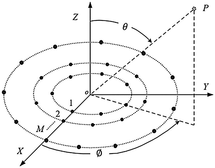
Figure 4: Concentric circular antenna arrays
The kth subarray amplitude coefficient
Generally, as shown in Fig. 5, the mth service beam from HAP can cover an area,
where,
and
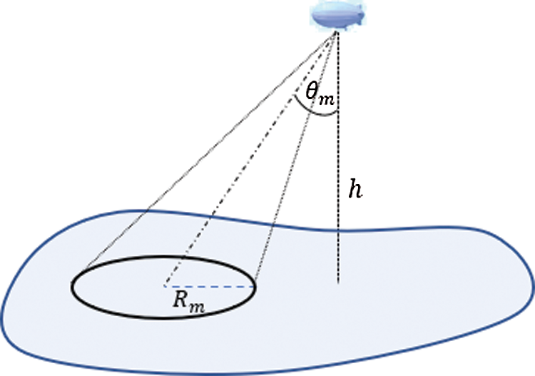
Figure 5: Spot beam coverage from HAP
Fig. 6 displays the cell area’s variation with the beam direction at different beamwidth values. As shown in this figure, for beam directions up to 40°, especially for small beamwidths, the beamwidth mainly controls the cell area where the effect of the beam direction is negligible. Increasing the beam direction beyond this limit results in a rapid increase in the cell area due to projection on the earth’s surface, where the cells become more elliptical.
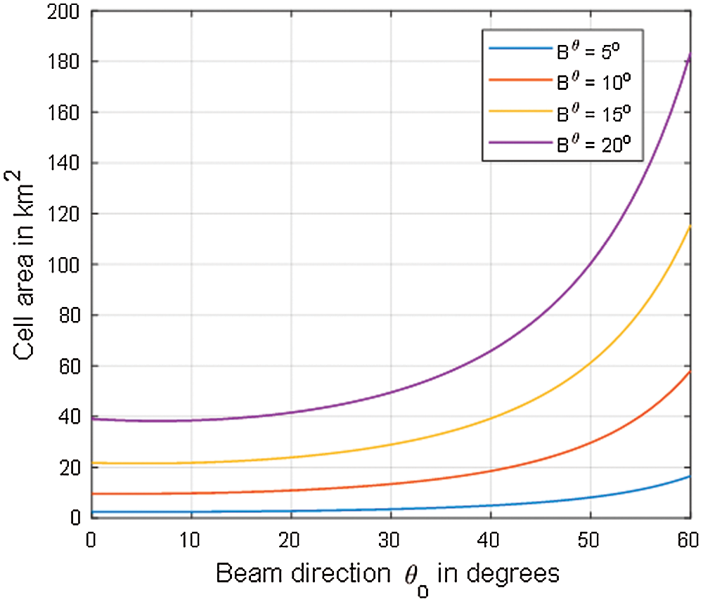
Figure 6: Variation of the coverage area with beam direction at different beamwidths
The system links the total number of students located in a cell with the cell area from the following relation:
where
Therefore, we can design the required coverage beam for a specific number of students and density for this area.
5.2 Communication Link Performance at the Student Premises
The signal level and probability of error at the student premises should be acceptable to achieve a specific communication link performance. The received signal power level at the student e-learning receiver input,
where,
where,
For example, suppose that the maximum beam downlink speed of the overall e-learning channel is 1 Gbps, and each student can be assigned 2 Mbps. In this case, the total number of simultaneously served students is less than or equal to 500. The service beam from HAP can be split into multibeam when the number of simultaneously served students is less than the beam capacity, and the coverage footprint can be extended to cover other remote regions. In the next section, we demonstrate the adaptive array structure at HAP that achieves the objective of adapting both the beam power gain and coverage area according to the remote area’s location and the number of students.
6 Numerical Results and Discussions
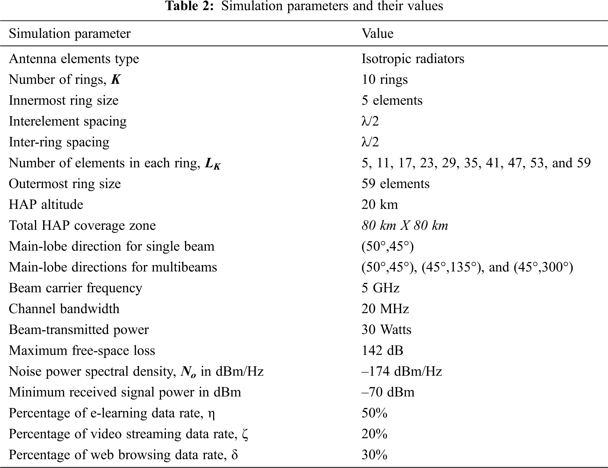
This experiment validates and tests the system’s capability to provide communication links with feasible performance and requirements. The system simulation parameters as well as physical and application settings are listed in Tab. 2. The onboard antenna array structure includes the number of elements and their distributions, interelement separation, operating frequency, bandwidth, HAP height, application data rates, percentages, etc. The test is in two scenarios: the formation of single-beam coverage and the capability to provide multibeam coverage based on the same weights or coefficients.
In this scenario, the concentric rings are weighted using Eq. (15), in which the maximum weight is assigned to the innermost ring, while the outermost ring has the lowest weight value. This tapered profile is proposed mainly for sidelobe reduction, which is essential for reducing the unwanted radiation toward other co-channel beams. We examined the radio coverage from HAP for a single beam generated toward an arbitrary direction of (
Fig. 7b shows the free-space path loss investigation; here, it ranges from −132.5 at the sub-HAP point to −142 dB at the end of coverage, and the maximum line-of-sight distance at the end of coverage is 60 km. In this case, the coverage area is considered a square of 80 km side length, which is suitable for local university coverage. The free-space loss affects the student premises’ received signal level and should be considered in the link budget calculations. Also, for remote regions that are far from the university campus, coverage can be secured by locating the HAP at a suitable location that can be directly seen from the university site. Consequently, higher-gain directional backhaul antennas are required at the university site to boost signals to/from the HAP.
If we consider 30 Watts of transmitted HAP beam power with a 10-dB extra attenuation margin, the resulting received power in dBm over the beam coverage region is as shown in Fig. 8a; the main-lobe spot is shown in dark red and has power levels of more than −50 dBm. For a channel bandwidth of 20 MHz, the probability of error for QPSK-modulated digital signals for the coverage region is as shown in Fig. 8b, in which the brown ellipse represents the area that has an error of less than
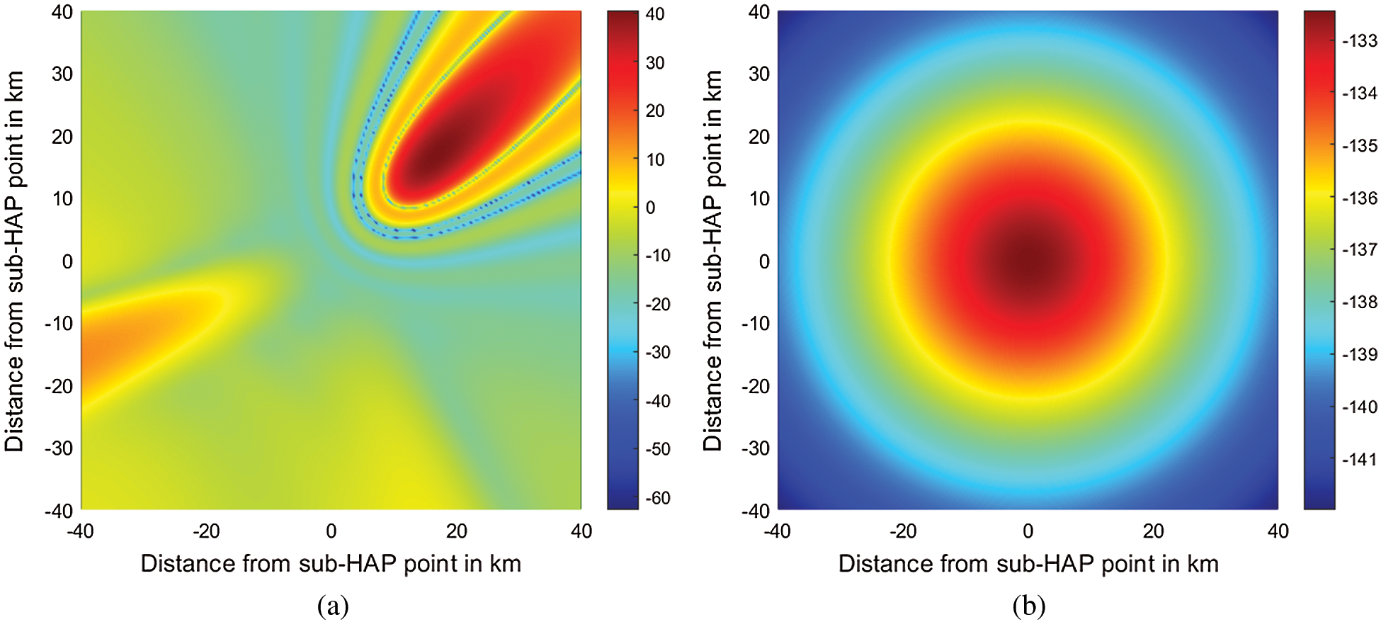
Figure 7: (a) HAP antennas gain (in dB) and cell footprint; (b) Free-space loss (in dB) that affects the transmitted signal from the HAP, which is located at a height of 20 km and covers a square area of
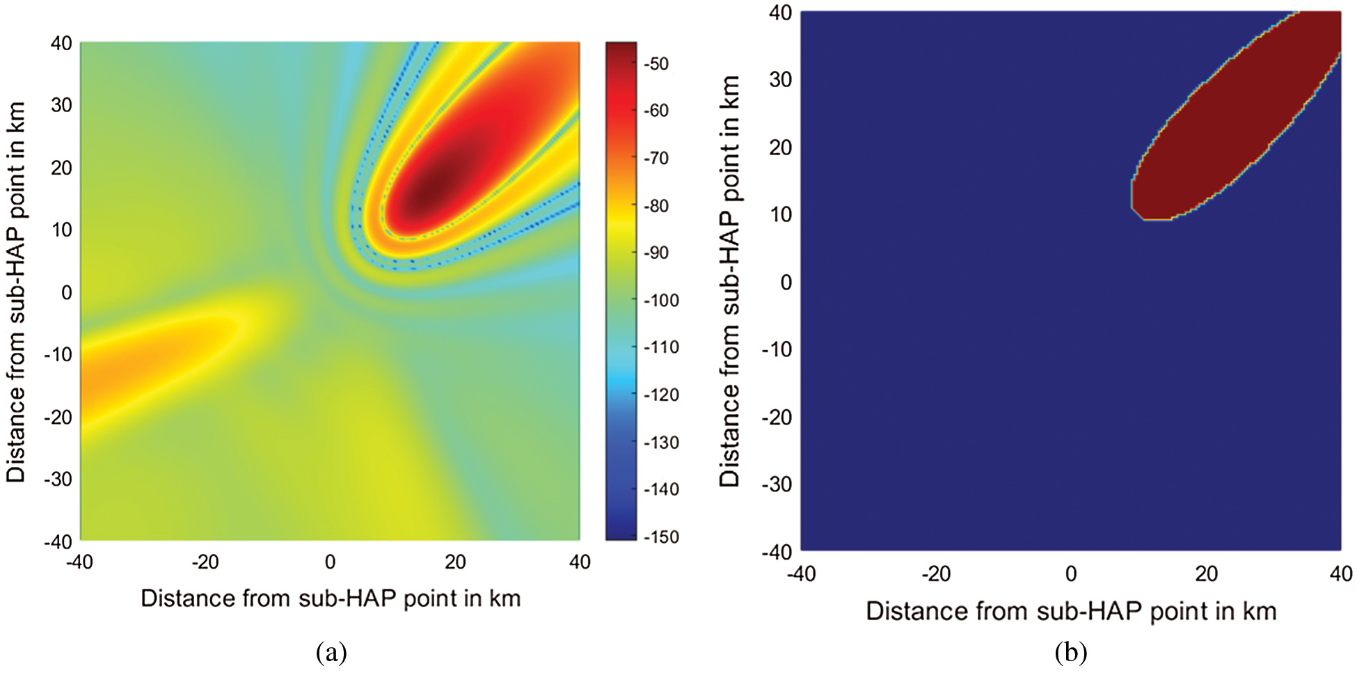
Figure 8: (a) Received signal strength (in dBm) and footprint; (b) Probability of error footprint for the single-beam coverage scenario from HAP. The brown region has
In this scenario, the antenna array beamforming system is examined for the formation of multibeams using the same elements and weighting function for feeding these elements as listed in Tab. 2. The weights in this figure are very similar to those in the single-beam scenario. They can be considered the sum of three individual weighting vectors corresponding to the individual beams in the multibeam structure. Generally, for
For example, as shown in Fig. 9a, three arbitrary beams directed at (
The received signal quality for the described multibeam scenario is depicted in Fig. 9b, in which the brown regions with a probability of error less than
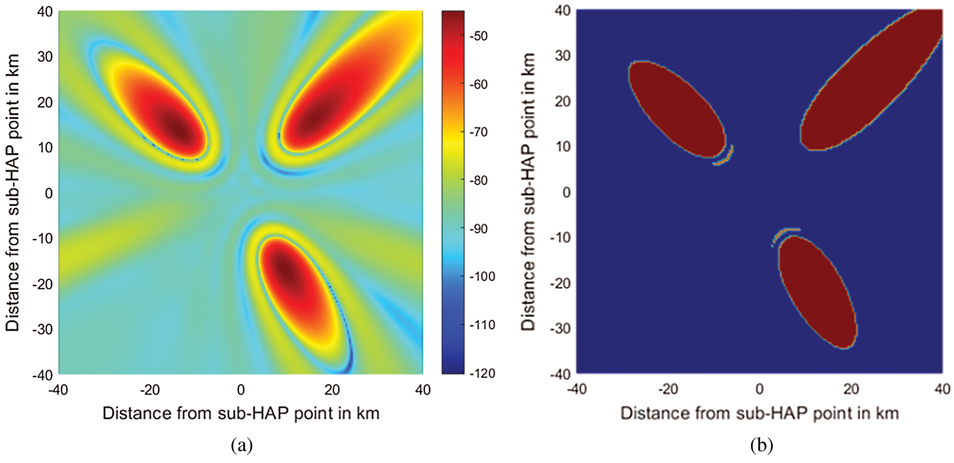
Figure 9: (a) Beam received signal strength (in dBm) and footprint for multibeam coverage scenario from HAP; (b) Probability of error footprint for the multibeam coverage scenario from HAP. The brown region has
This paper proposed a novel end-to-end communication network for robust, fast deployment of efficient e-learning services in remote areas using a high-altitude platform (HAP) system. The network design was examined and investigated, and we classified the data from the server into three categories corresponding to different services: e-learning activities, video streaming, and web browsing. The highest priority was given to online classes and discussion applications, while the other applications were assigned lower priorities. Adaptive antenna arrays were proposed for coverage beam adaptation and distribution to ensure efficient resource management and improve the overall throughput entering the HAP link. These beams were manipulated and dynamically adapted using MAC and application layers parameters such as the services’ data rates. The proposed model was simulated. The system’s performance was analyzed, and the results showed that using an adaptive antenna array can help us secure high quality and high rate of transmission data at the student premises, and the requirements for both single-beam and multibeam coverage scenarios are feasible.
Funding Statement: The authors would like to thank Taif University for supporting this work under project number (1-441-82).
Conflicts of Interest: The authors declare that they have no conflicts of interest to report regarding the present study.
1. COVID-19, “Centers for Disease Control and Prevention (CDC),” 2020. [Online]. Available at: https://www.cdc.gov/coronavirus/2019-nCoV/index.html. [Google Scholar]
2. COVID-19 Coronavirus Pandemic, 2021. [Online]. Available at: https://www.worldometers.info/coronavirus. [Google Scholar]
3. Global Health – Saudi Arabia, 2021. [Online]. Available at: https://www.cdc.gov/globalhealth/countries/saudi_arabia/default.htm. [Google Scholar]
4. Network Coverage Maps, 2021. [Online]. Available at: https://www.gsma.com/coverage/. [Google Scholar]
5. S. C. Arum, D. Grace and P. D. Mitchell, “A review of wireless communication using high-altitude platforms for extended coverage and capacity,” Computer Communications, vol. 157, pp. 232–256, 2020. [Google Scholar]
6. A. Mohammed and Z. Yang, “Broadband communications and applications from high altitude platforms,” International Journal of Recent Trends in Engineering, vol. 1, no. 3, pp. 293–243, 2009. [Google Scholar]
7. S. Karapantazis and F. Pavlidou, “Broadband communications via high-altitude platforms: A survey,” IEEE Communications Surveys & Tutorials, vol. 7, no. 1, pp. 2–31, 2005. [Google Scholar]
8. M. Oodo, R. Miura, Y. Hase, T. Inaba, T. Sakamoto et al., “Measurement results of digital beamforming array antenna onboard stratospheric platform in the band 31/28 GHz,” in Proc. of 5th Int. Sym. on Wireless Personal Multimedia Communications (WPMCHonolulu, USA, October 2002. [Google Scholar]
9. Z. Xu, Y. Zakharov and G. White, “Vertical antenna array and spectral reuse for ring-shaped cellular coverage from high altitude platform,” in Proc. Loughbourgh Antennas and Propagation (LAPCLoughborough, UK,November 2006. [Google Scholar]
10. T. Isernia, P. J. Ares, O. M. Bucci, M. D’Urso, J. F. Gomez et al., “A hybrid approach for the optimal synthesis of pencil beams through array antennas,” IEEE Transactions Antennas and Propagation, vol. 52, no. 11, pp. 2912–2918, 2004. [Google Scholar]
11. S. M. Tseng, Y. F. Chen and H. H. Fang, “Cross PHY/APP layer user grouping and power allocation for uplink multiantenna NOMA video communication systems,” IEEE Systems Journal, vol. 14, no. 3, pp. 3351–3359, 2020. [Google Scholar]
12. M. Abdelgadir and R. Saeed, “Evaluation of performance enhancement of OFDM based on cross layer design (CLD) IEEE 802.11p standard for vehicular ad-hoc networks (VANETscity scenario,” International Journal of Signal Processing Systems, vol. 8, no. 1, pp. 1–7, 2020. [Google Scholar]
13. J. Tang, W. P. Tay and T. Q. Quek, “Cross-layer resource allocation with elastic service scaling in cloud radio access network,” IEEE Transactions on Wireless Communications, vol. 14, no. 9, pp. 5068–5081, 2005. [Google Scholar]
14. S. Xinghua, W. Xiaoxiang and W. Weiling, “Cross-layer resource allocation for the downlink of SDMA systems,” in Proc. Int. Workshop on Cross Layer Design (IWCLDJinan, China, 2007. [Google Scholar]
15. I. Zakia, S. Tjondronegoro, K. Iskandar and A. Kurniawan, “Performance comparisons of adaptive MVDR and received LS beam-forming on the downlink time varying channel of HAP system,” in Proc. 19th Asia-Pacific Conf. on Communications (APCCKuala Lumpur, Malaysia,2013. [Google Scholar]
16. M. Abdelgadir, R. Saeed and A. Babiker, “Cross layer design approach for efficient data delivery based on IEEE 802.11P in vehicular ad-hoc networks (VANETS) for city scenarios,” International Journal on Ad Hoc Networking Systems, vol. 8, no. 4, pp. 1–12, 2018. [Google Scholar]
17. S. J. Nawaz, B. Mansoor, S. K. Sharma, S. M. Gulfam and M. N. Patwary, “Location-aware and superimposed-pilot based channel estimation of sparse HAP radio communication channels,” in Proc. IEEE 85th Vehicular Technology Conf. (VTC SpringSydney, Australia, pp. 1–7, 2017. [Google Scholar]
18. Z. Lian, L. Jiang, C. He and D. He, “User grouping and beamforming for HAP massive MIMO systems based on statistical-eigenmode,” IEEE Wireless Communications Letters, vol. 8, no. 3, pp. 961–964, 2019. [Google Scholar]
19. L. Dong, A. Petropulu and H. Poor, “Weighted cross-layer cooperative beamforming for wireless networks,” IEEE Transactions on Signal Processing, vol. 57, no. 8, pp. 3240–3252, 2009. [Google Scholar]
20. B. Li, H. Li and J. Zurada, “Cross-layer design of joint beamforming and random network coding in wireless multicast networks,” IEEE Communications Letters, vol. 18, no. 12, pp. 2173–2176, 2014. [Google Scholar]
21. J. Wang, P. Huang, X. Wang and Y. Yang, “Cross-layer scheduling for physical layer secrecy and queue stability in a multi-user system,” in Proc. IEEE Global Communications Conf. (GLOBECOMAtlanta, USA,2013. [Google Scholar]
22. J. Yu, Y. Cai, Y. Ma, D. Zhang and Y. Xu, “A Cross-layer design of packet scheduling and resource allocation for multiuser MIMO-OFDM systems,” in Proc. 6th Int. Conf. on Information, Communications & Signal Processing, Singapore, 2007. [Google Scholar]
23. W. Huang, K. Letaief and Y. Zhang, “Cross-layer multi-packet reception based medium access control and resource allocation for space-time coded MIMO/OFDM,” IEEE Transactions on Wireless Communications, vol. 7, no. 9, pp. 3372–3384, 2008. [Google Scholar]
24. R. Malekian, A. Abdullah and R. Saeed, “A Cross-layer scheme for resource reservation based on multi-protocol label switching over mobile IP version 6,” International Journal of the Physical Sciences, vol. 6, no. 11, pp. 2710–2717, 2011. [Google Scholar]
25. Y. Dong, M. Hossain, J. Cheng and V. Leung, “Dynamic cross-layer beamforming in hybrid powered communication systems with harvest-use-trade strategy,” IEEE Transactions on Wireless Communications, vol. 16, no. 12, pp. 8011–8025, 2017. [Google Scholar]
26. Y. Dong, M. Syed and Y. Jin, “Utilizing beamforming for random access – a cross-layer paradigm,” in Proc. IEEE 60th Vehicular Technology Conf., Los Angeles, USA, vol.7, pp. 5160–5164, 2004. [Google Scholar]
27. J. Choi and C. Joo, “Cross-layer optimization for satellite-terrestrial heterogeneous networks,” in Proc. Int. Conf. on Computing, Networking and Communications (ICNCHonolulu, USA, pp. 276–281, 2014. [Google Scholar]
28. K. Xiao, C. Li and J. Zhao, “LSTM based multiple beamforming for 5G HAPS IoT networks,” in Proc. 15th Int. Wireless Communications & Mobile Computing Conf. (IWCMCTangier, Morocco, pp. 1895–1900, 2019. [Google Scholar]
29. R. Saeed, S. Khatun, B. M. Ali and M. Khazani, “A joint PHY/MAC cross-layer design for UWB under power control,” Computers and Electrical Engineering, vol. 36, no. 3, pp. 455–468, 2010. [Google Scholar]
30. P. Sudheesh, M. Mozaffari, M. Magarini, W. Saad and P. Muthuc, “Sum-rate analysis for high altitude platform (HAP) drones with tethered balloon relay,” IEEE Communications Letters, vol. 22, no. 6, pp. 1240–1243, 2017. [Google Scholar]
31. S. Arum, D. Grace, P. Mitchell, M. Zakaria and N. Morozs, “Energy management of solar-powered aircraft-based high-altitude platform for wireless communications,” Electronics, vol. 9, no. 1, pp. 179, 2020. [Google Scholar]
32. G. White, E. Falletti, Z. Xu, D. Borio, F. Sellone et al., “Report on adaptive beamforming algorithms for advanced antenna types for aerial platform and ground terminals, CAPANINA Project,” CAPANINA Project, Deliverable No. D17, 31st Jan 2006. [Google Scholar]
33. M. Dessouky, H. Sharshar and Y. Albagory, “Efficient sidelobe reduction technique for small-sized concentric circular arrays,” Progress in Electromagnetics Research, vol. 65, pp. 187–200, 2006. [Google Scholar]
34. J. Proakis and M. Salehi, “Digital communications,” McGraw-Hill Education, 5th ed., New York, US, pp. 23–64,1995. [Google Scholar]
 | This work is licensed under a Creative Commons Attribution 4.0 International License, which permits unrestricted use, distribution, and reproduction in any medium, provided the original work is properly cited. |