DOI:10.32604/iasc.2021.018595
| Intelligent Automation & Soft Computing DOI:10.32604/iasc.2021.018595 | |
| Article |
Grey Wolf Optimizer-Based Fractional MPPT for Thermoelectric Generator
1Mechanical Engineering Department, College of Engineering & Islamic Arch., Umm Alqura University, Makkah, Saudi Arabia
2College of Engineering at Wadi Addawaser, Prince Sattam Bin Abdulaziz University, 11911, Al-Kharj, Saudi Arabia
3Electrical Engineering Department, Faculty of Engineering, Minia University, 61517, Minia, Egypt
4Production Engineering and Design Department, Faculty of Engineering, Minia University, 61517, Minia, Egypt
5Mechanical Engineering Department, Faculty of Engineering, Sohag University, Sohag, Egypt
*Corresponding Author: Hegazy Rezk. Email: hr.hussien@psau.edu.sa
Received: 12 March 2021; Accepted: 13 April 2021
Abstract: The energy harvested from a thermoelectric generator (TEG) relies mostly on the difference in temperature between the hot side and cold side of the TEG along with the connected load. Hence, a reliable maximum power point tracker is needed to force the TEG to operate close to the maximum power point (MPP) with any variation during the operation. In the current work, an optimized fractional maximum power point tracker (OFMPPT) is proposed to improve the performance of the TEG. The proposed tracker is based on fractional control. The optimal parameters of the OFMPPT have been determined using the grey wolf optimizer (GWO). To prove the superiority of GWO, the results are compared with particle swarm optimization (PSO) and genetic algorithm (GA). The largest fitness function, the lowest standard deviation, and the maximum efficiency are achieved by GWO. The goal of the suggested OFMPPT is to overcome the two main issues in conventional trackers. They are the slow dynamic of the traditional incremental resistance tracker (INRT) and high steady-state fluctuation around the MPP in the very common perturb & observe tracker (POT). The main finding confirmed the superiority of OFMPPT compared with INRT and POT for both dynamic and steady-state responses.
Keywords: Grey wolf optimizer; fractional control; thermoelectric generator; MPPT
The increasing demand for electricity has urged power supply companies to build more power stations. However, power plants are huge manufacturing facilities, and their operation can affect the climate. As an alternative solution, renewable generators have received a lot of attention as component of distributed production because they can pressure on the main grid system by supplying a few local loads. There are different kinds of renewable energy, including solar energy, wind energy, biomass energy, and geothermal energy [1]. Thermoelectric generators (TEGs) are used to convert solar radiation or any waste heat into electrical energy [2]. TEG is a solid-state semiconductor device, which converts a temperature difference to direct current using the Seebeck phenomenon [3]. The Seebeck phenomenon directly converts heat energy into a voltage potential. It appears because of the movement of charge carriers within semiconductors. Recently, the use of TEG to recover waste heat energy has increased rapidly with applications in fields such as remote sensing [4] and automotive [5], geothermal [6], satellite [7], and industrial power plants [8], besides being integrated with photovoltaic [9] and solar thermal systems. In most practical TEG systems, the required capacity depends mainly on the application [10]. Therefore, a certain number of TEG modules must be connected in series and/or parallel to provide the required power rating [11].
The power produced by a TEG relies mostly on the difference in temperature between the hot side and cold side of the TEG along with the connected load [2]. According to maximum power theorem, the maximum power of a TEG is achieved when the load resistance equals the internal resistance of the TEG [3]. Consequently, maximum power point tracking (MPPT) is essential to force the TEG to operate close to the maximum power point (MPP) with any variation during the operation. To do this, a DC-DC converter matches the load seen by the TEG to its actual inner resistance by adjusting the duty cycle.
Different MPPT methods are used in applications like photovoltaic systems [12,13], fuel cell systems [14], wind energy systems, thermoelectric generation [15], and hybrid systems [2]. These methods include perturb and observe, hill-climbing, incremental conductance, and incremental resistance [12]. These methods have some limitations. For example, perturb and observe method is characterized by high fluctuation around the MPP. However, the incremental resistance approach can mitigate these fluctuations, but it has a slow dynamic response, particularly with fast change in the load. To solve such difficulties and to improve the output performance of a TEG, the current work proposes an optimized fractional maximum power point tracker (OFMPPT). The tracker is based on fractional control. The fractional-order control contains a non-integer order which is preferred to integer-order control owing to its benefits. It offers extra flexibility in design, and it shows superior outcomes such as high robustness [16]. The optimal parameters of the OFMPPT have been determined using a grey wolf optimizer (GWO). To prove the superiority of GWO, the results are compared with particle swarm optimization (PSO) and genetic algorithm (GA). The key goal of the suggested OFMPPT is to overcome the two main issues in the conventional trackers. They are the slow dynamic of the traditional incremental resistance tracker (INRT) and high steady-state fluctuation around the MPP in the very common perturb & observe tracker (POT).
The contributions of the current research work are:
• A grey wolf optimizer estimates the best parameters of fractional order MPPT for a thermoelectric generator system.
• There is a comprehensive comparison with other optimization algorithms: particle swarm optimization and genetic algorithm.
• The superiority of optimized fractional MPPT is demonstrated for both dynamic and steady-state responses
The rest of the paper is organized as follows. Section 2 present the mathematical model of the thermoelectric generator. An overview of the maximum power point tracking techniques is described in Section 3. Section 4 presents the results. Last, the main finding and future research are outlined in Section 5.
2 Mathematical Model of a Thermoelectric Generator
The overview of the TEG module is shown in Fig. 1a. The fundamental element of the TEG is a thermocouple that contains p-type and n-type semiconductors. These conductors are electrically interconnected in series using a metal strip. To build a TEG module, several p-type and n-type pairs are interconnected to increase the required rating of the output power as presented in Fig. 1b. They are electrically connected in series to increase the voltage potential, and thermally in parallel to decrease the thermal resistance [6]. The couples are inserted between two parallel ceramic plates to form a hot side and a cold side. When there is a temperature difference between the hot side and cold side, a direct current flows in the load as illustrated in Fig. 1c.
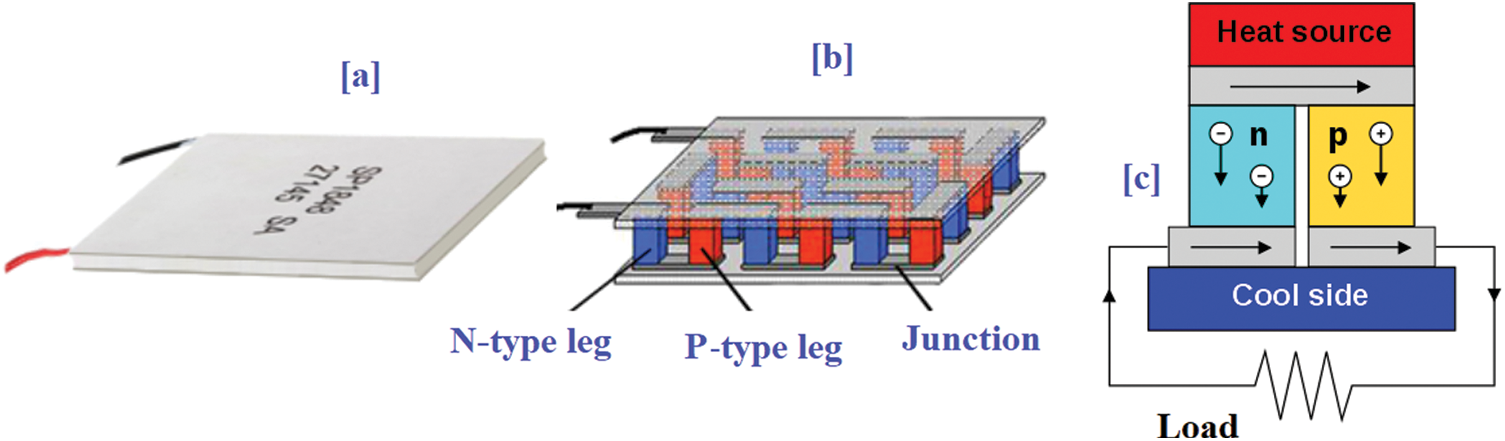
Figure 1: Construction of the TEG
The core idea of the thermoelectric generator is based on the Seebeck effect. The open circuit voltage of TEG can be estimated using the following relation [6]:
where:
Th denotes the hot side temperature of the TEG.
Tc denotes the cold side temperature of the TEG.
ΔT is the temperature difference.
α denotes the Seebeck coefficient.
Considering the steady-state energy balance on both sides of the TEG, the absorbed heat from the thermal load and the heat passed by the heat sink can be formulated as follows [15]:
where:
Rteg is the internal resistance of the TEG.
The output power of the TEG can be calculated considering the difference between the hot side and the cold side as follows:
where:
Three MPPT approaches are studied in this paper: perturb & observe, incremental resistance based on integer control, and optimized incremental resistance based on fractional control.
The key merit of the P&O approach is its simplicity. It is very common and used with different applications. P&O adjusts the converter duty cycle during the tracking process [12]. The MATLAB model of the P&O method integrated with the TEG and a DC converter is presented in Fig. 2. The TEG voltage and current are measured, then the TEG power is calculated. Based on the change in the TEG power, the duty cycle is updated, increasing the duty cycle when there is a positive change in power. Octonary, decreasing the duty cycle with negative change in power. The drawback of this is method is the high fluctuation around the MPP.
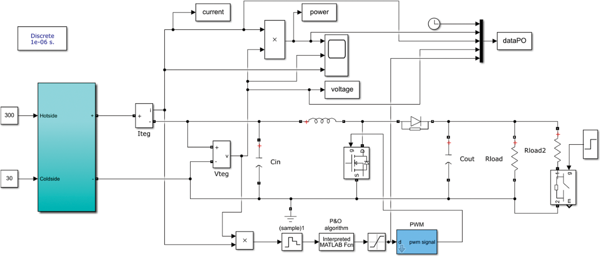
Figure 2: MATLAB model of the perturb & observe method
3.2 INR Based on Integer Control
The core idea of incremental resistance comes from the reality that the derivative of output power with respect to current is zero at the maximum power point [12]. The error signal e(t) at MPP can be derived as follows:
Therefore, the error signal can be formulated as follows:
The error is very tiny at the maximum power point. So, to remove the oscillations at MPP, the step size of the INR method is selected to vary with the amount of the error. To do this, a discrete integrator is used as described in Fig. 3. The error signal is used as an input to the discrete integrator and the gain of the integrator is the scaling factor (k = 0.8) to adjust the step size. The drawback of this is method is the slow dynamic response especially when there are fast changes in the load.
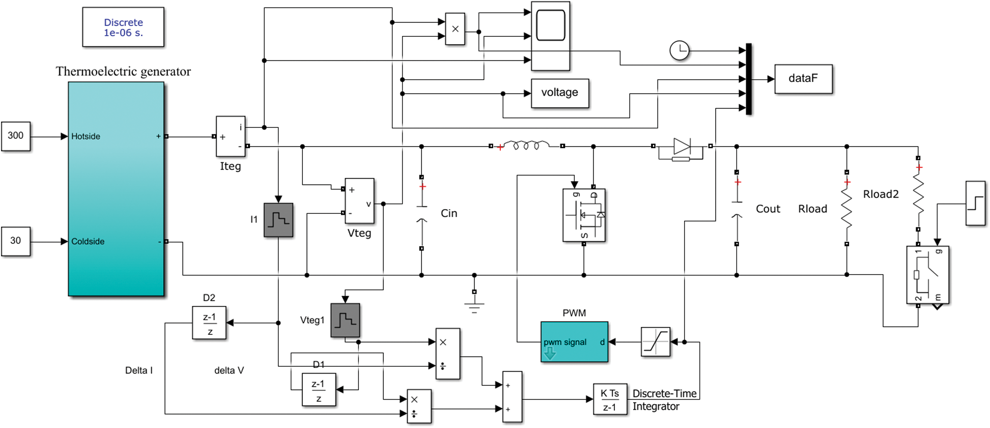
Figure 3: MATLAB model of INR based on integer control
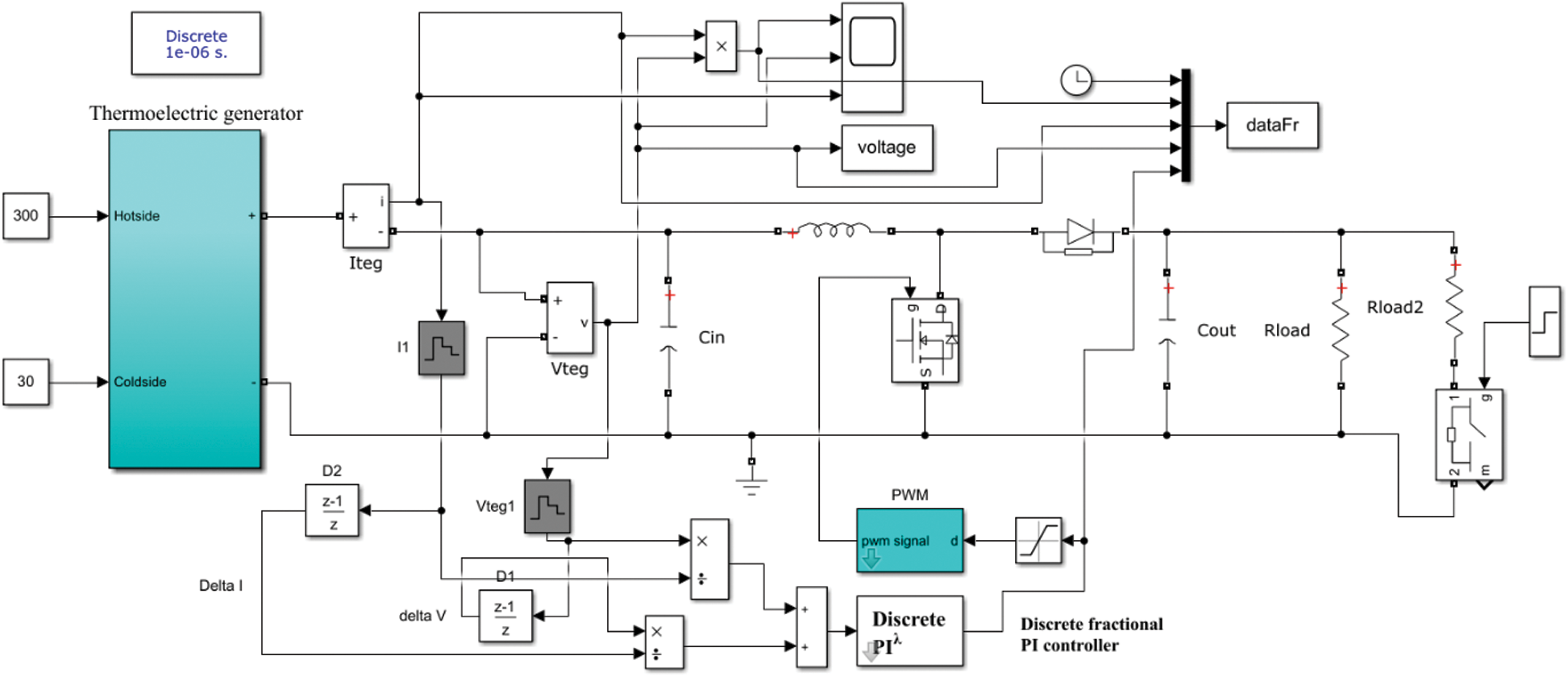
Figure 4: MATLAB model of optimized fractional INR based on fraction control
To improve the dynamic response of the conventional incremental resistance method, a fraction control is adopted. The optimized fractional INR (OFINR) tracker uses a fractional PI instead of an integer integrator. Fractional control has been used in different engineering fields [16]. It contains a non-integer order that has several advantages like flexibility in design and high robustness. The fractional PI transfer function can be defined as follows:
where e denotes the error, Tc denotes the controller transfer function, the integral and proportional are
Four optimization methods are used to determine the optimal parameter of OFINR. These optimizers are manta ray foraging optimization, particle swarm optimization, grey wolf optimizer, and genetic algorithm. During the optimization process, the parameters of the optimized fraction INR method: integration gain, proportional gain, and fraction order and are used s decision variable whereas the fitness function that required to be maximum is represented by the harvested energy from the thermoelectric generator.
3.3.1 Particle Swarm Optimization
PSO is one of the most famous optimizers. The original version was suggested by Kennedy and Eberhart [17]. It is very simple and easy to execute. The core idea of PSO comes from the flocking behavior of birds. Every particle is a candidate solution, and it is made of two vectors: location and velocity. The location vector includes the values for each of the variables in the problem. To modify the location of particles, the velocity is considered. The velocity defines the magnitude and direction of step size for each dimension and each particle independently. The details of the mathematical representation and physical distribution can be found in Zhang et al. [17]. The updating process for velocity and location of particles can be defined as follows:
where V is the velocity, Pbest is the best solution, gbest is the global best. c1 and c2 denote cognitive and social factors. The values of c1 and c2 are 1.5 and 2, respectively. r1 and r2 are random values in range of [0 1].
The original version of GWO was proposed by Mirjalili et al. [18]. It simulates the leadership hierarchy and hunting mechanism of grey wolves. Four types of grey wolves are used to model the hierarchy: alpha, beta, delta, and omega. In addition, the optimization process has three important steps: hunting or searching for prey, encircling prey, and attacking prey. The details of the mathematical representation and physical distribution can be found in Mirjalili et al. [18]. The grey wolves surround prey throughout hunting. This can be represented as follows:
where
t denotes the current iteration.
The vectors
where
John Henry Holland invented the genetic algorithm (GA) in the 1970s. GA is a random-based traditional evolutionary algorithm. It is based on Darwin’s theory of evolution. GA starts with a random generation of the initial population, and then, “selection,” “crossover,” and “mutation” occur until the maximum generation is reached. The details of the mathematical representation and physical distribution can be found in Katoch et al. [19].
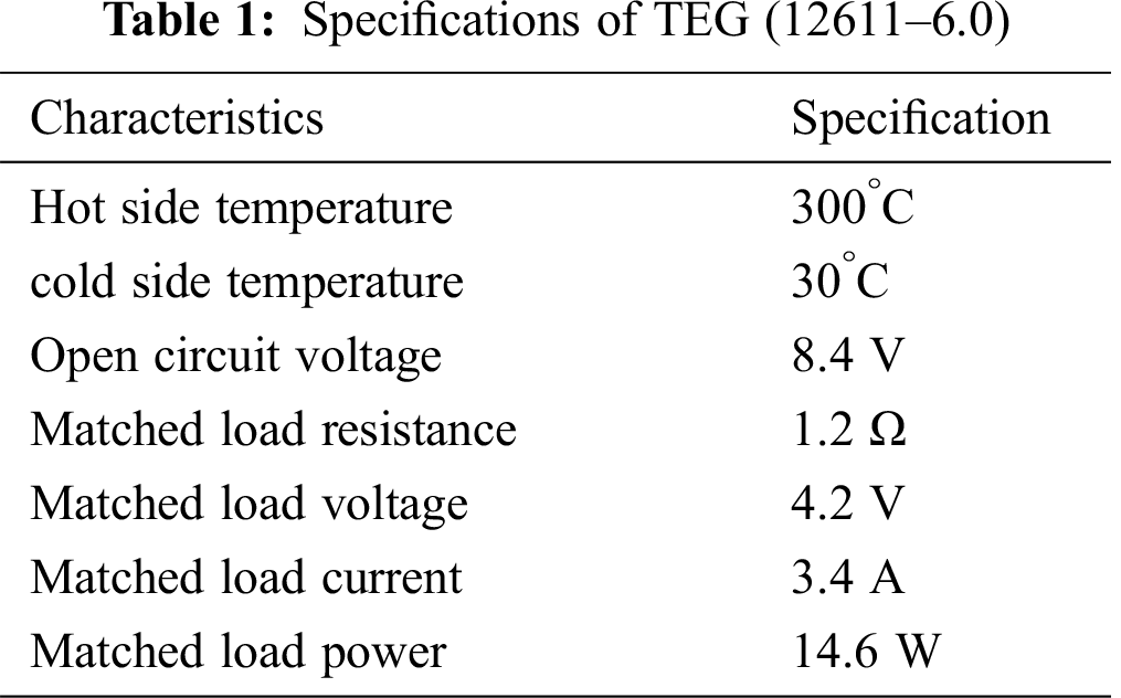
First, to examine and analyze the output of a thermoelectric generator with varying temperature differences, a MATLAB code has been designated. In the current study, TEG (12611‒6.0) is considered. Tab. 1 presents its specifications. Fig. 5 illustrates the TEG power versus current with variation of the hot side temperature. The cold side temperature is fixed at 30 C. Note that there is a good agreement between simulated data (blue line) and manufacturing data (yellow points).
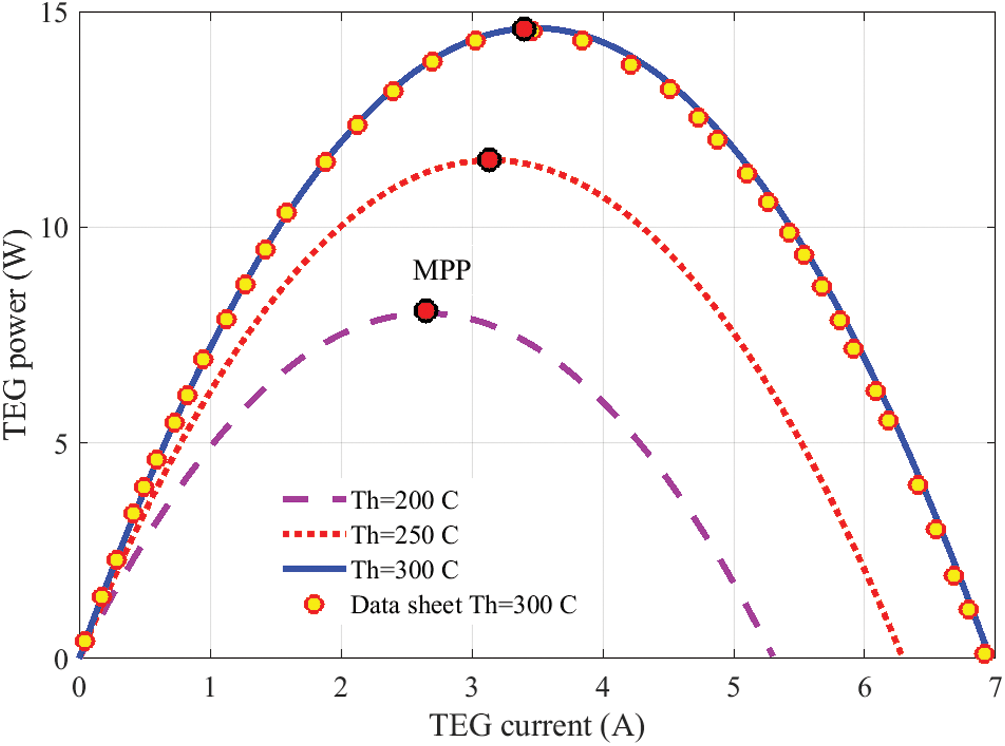
Figure 5: TEG power against current
To determine the optimal parameters of OFINR, three optimizers, PSO, GA, and GWO are considered. To make the comparison fair, the population size and the maximum number of iterations for all optimizers are set to 10 and 25, respectively. During the optimization procedure, the harvested energy of the TEG is used as the fitness function, which must be the least maximum. The undetermined parameters of the OFINR model are designated as decision variables. The best parameters of OFINR applying PSO, GA, and GWO are presented in Tab. 2. To demonstrate the consistency of the considered optimizers, each one is executed 30 times. The statistical assessment of the considered optimizers is shown also in Tab. 2.
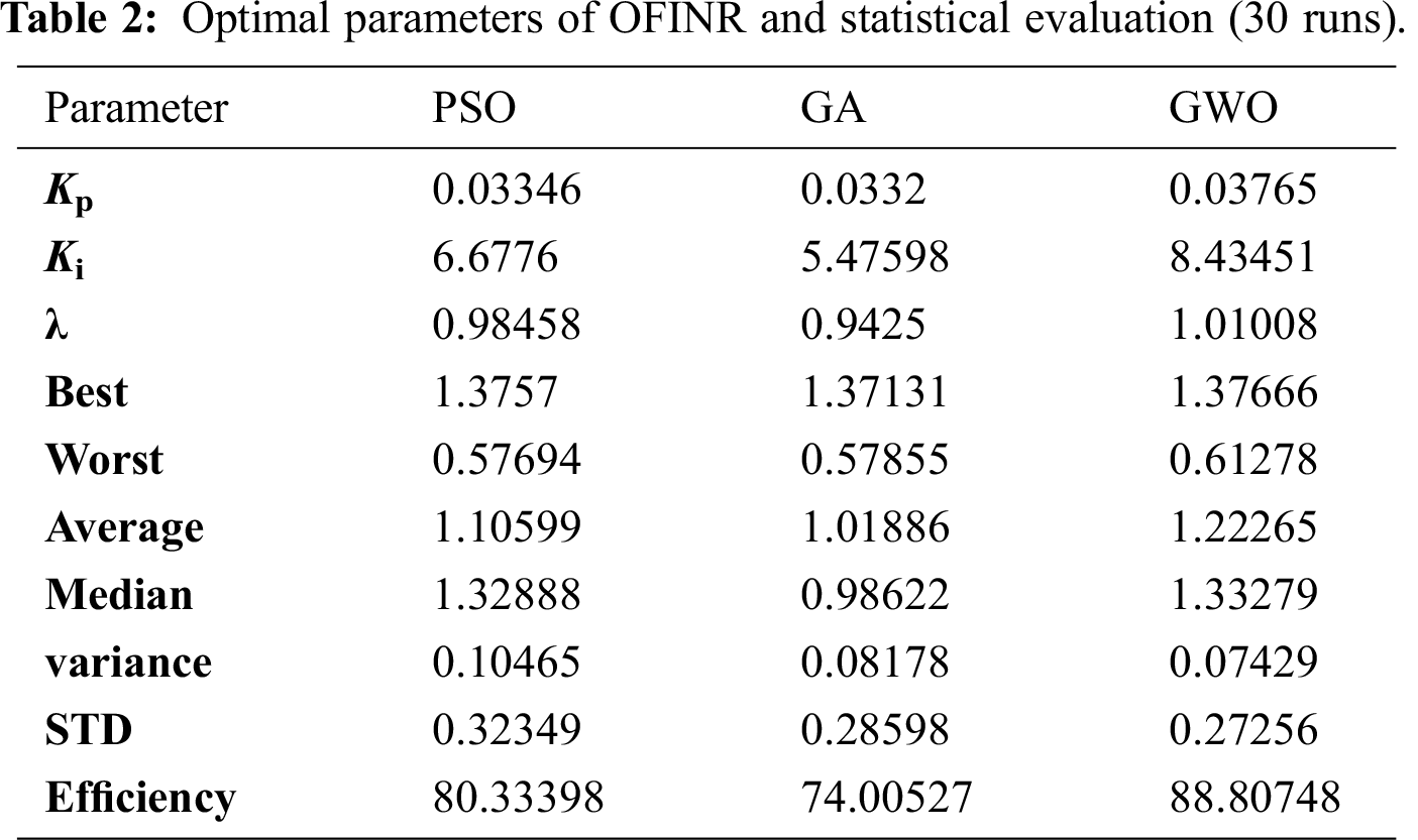
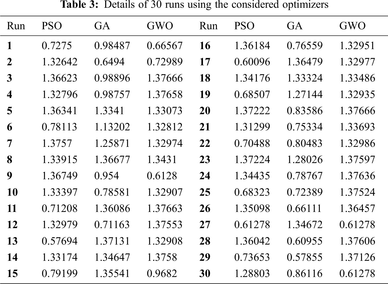
Considering the data presented in Tab. 3, it can be observed that the GWO yields the best performance. The value of the average fitness function ranges between 1.22265 and 1.10599. The largest average fitness value, 1.22265, is reached using GWO followed by 1.10599 using PSO. The lowest STD, 0.27256, is achieved by GWO. The average efficiency values are 80.33%, 74.00%, and 88.80%, respectively for PSO, GA, and GWO. The details of 30 run for using considered optimizers is presented in Tab. 3. The variation of fitness function through parameter identification using different optimization is shown in Fig. 6.
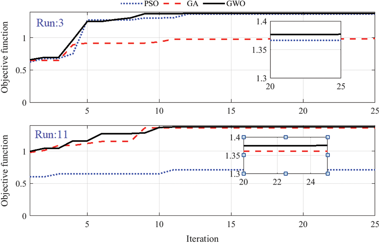
Figure 6: Variation of fitness function through parameter identification
After determining the optimal parameters of OFINR, the tracking performance of the proposed OFINR method is tested and evaluated by MATLAB simulation with varying loads. The idea of load variation is to test the dynamic tracking response of the proposed tracker. The MATLAB TEG system is presented in Fig. 4. It contains one TEG module and a DC-DC converter operating in continuous conducted current mode with a switching frequency of 30 kHz, an input inductance of 1 mH, an output capacitor of 47 μF, and 15 Ω resistive load. At a time of 0.4 sec, an additional resistance of 15 Ω is connected in parallel with the load. The MPPT method is used as a controller to feed the boost with an appropriate duty cycle. For the conventional INR method, the gain of discrete integrator is selected to be 0.8. For OFINR, the parameters of fractional PI are 0.03765, 8.43451, and, 1.01008 respectively for proportional gain, integral gain, and fractional order as determined using GWO and presented in Tab. 3.
Fig. 7 shows the dynamic response of TEG output power for the considered MPPT techniques while changing the load. It can be observed that the suggested OFINR reaches the maximum power of 14.6 W very rapidly. By comparison, the conventional INR needs about 0.3 s to reach the MPP. The fluctuations around the MPP are removed thanks to OFINR compared with the conventional P&O method. At the time of 0.4, the load resistance is changed from 15 Ω to 7.5 Ω. The suggested OFINR quickly comes back to the maximum power point. While the P&O and conventional INR need more time to update the value of the duty cycle. The corresponding variation of voltage, current, and converter duty cycle are demonstrated in Figs. 8, 9, and 10, respectively.
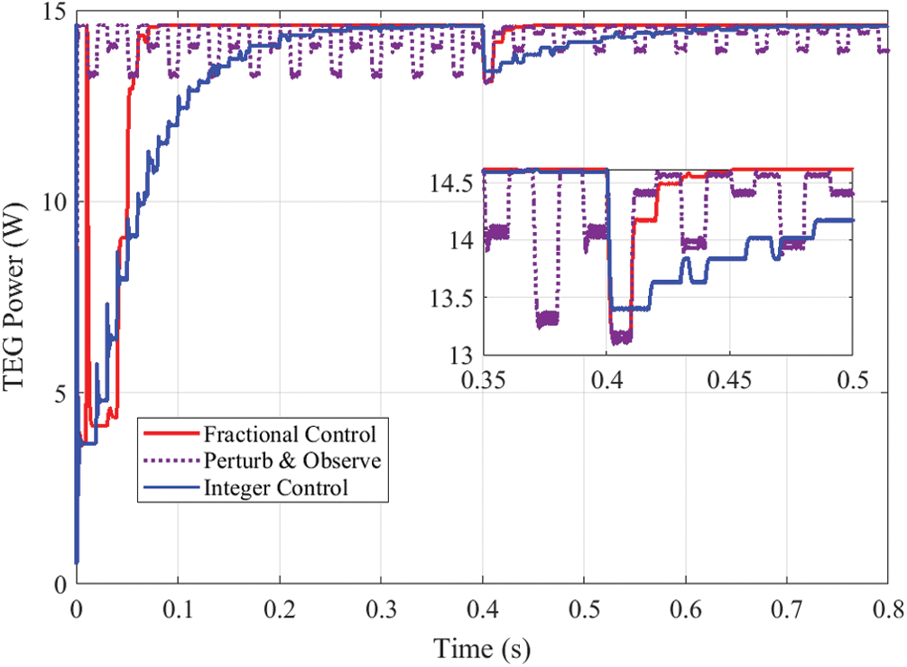
Figure 7: TEG power with different MPPTs under load variation
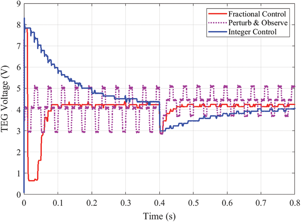
Figure 8: TEG voltage with different MPPTs under load variation
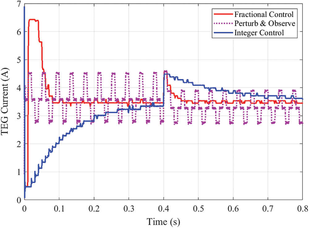
Figure 9: TEG current with different MPPTs under load variation
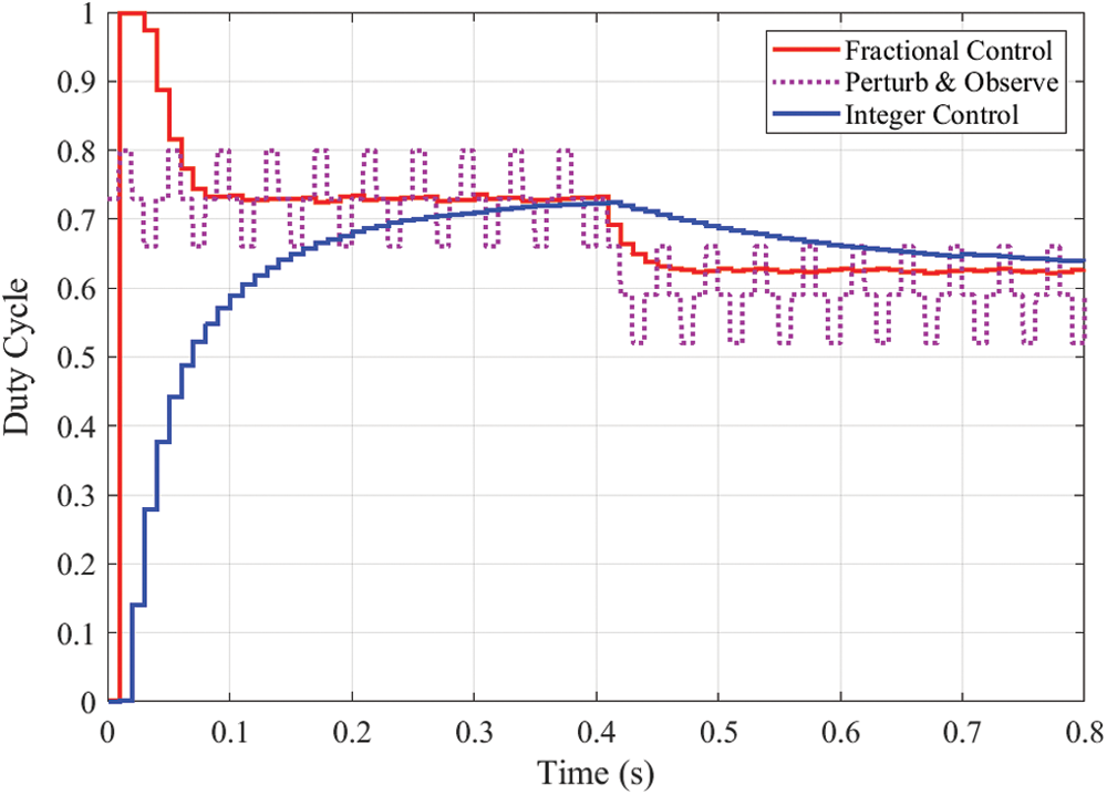
Figure 10: Duty cycle with different MPPTs under load variation
To improve the dynamic response of conventional incremental resistance (INR) tracking technique and remove the steady-state fluctuations of the perturb and observe (P&O) method, in this paper, an optimized fractional INR (OFINR) technique is proposed. This technique increases the energy harvested from a thermoelectric generator (TEG). First, the optimal parameters of OFINR were determined using a grey wolf optimizer (GWO). To prove the superiority of GWO, the results are compared with particle swarm optimization (PSO) and genetic algorithm (GA). The average fitness function value ranged between 1.22265 and 1.10599. The largest average fitness value, 1.22265, is reached using GWO, followed by 1.10599 using PSO. The lowest STD, 0.27256, is achieved by GWO. The average efficiency values are 80.33%, 74.00%, and 88.80% respectively for PSO, GA, and GWO. These results confirm the superiority of GWO over PSO and GA to determine the parameters of OFINR. After determining the optimal parameters of OFINR, the tracking performance of the proposed OFINR method is compared with conventional INR and the P&O method during changes in the load. The main finding confirmed the superiority of OFMPPT over INRT and POT for both dynamic and steady-state responses.
Funding Statement: The authors received no specific funding for this study.
Conflicts of Interest: The authors declare that they have no conflicts of interest to report regarding the present study.
1. H. Rezk and A. Fathy, “Performance improvement of PEM fuel cell using variable step-size incremental resistance MPPT technique,” Sustainability, vol. 12, no. 14, pp. 5601, 2020. [Google Scholar]
2. M. N. Ibrahim, H. Rezk, M. Al-Dahifallah and P. Sergeant, “Hybrid photovoltaic-thermoelectric generator powered synchronous reluctance motor for pumping applications,” IEEE Access, vol. 7, pp. 146979–146988, 2019. [Google Scholar]
3. W. H. Chen and Y. X. Lin, “Performance comparison of thermoelectric generators using different materials,” Energy Procedia, vol. 158, pp. 1388–1393, 2019. [Google Scholar]
4. R. J. Stevens, S. J. Weinstein and K. S. Koppula, “Theoretical limits of thermoelectric power generation from exhaust gases,” Applied Energy, vol. 133, pp. 80–88, 2014. [Google Scholar]
5. K. Huang, Y. Yan, B. Li, Y. Li and K. Li, “A novel design of thermoelectric generator for automotive waste heat recovery,” Automotive Innovation, vol. 1, no. 1, pp. 54–61, 2018. [Google Scholar]
6. H. Rezk, Z. M. Ali, O. Abdalla, O. Younis, M. R. Gomaa et al., “Hybrid moth-flame optimization algorithm and incremental conductance for tracking maximum power of solar PV/thermoelectric system under different conditions,” Mathematics, vol. 7, no. 10, pp. 875, 2019. [Google Scholar]
7. M. N. Ibrahim, H. Rezk, M. Al-Dahifallah and P. Sergeant, “Hybrid photovoltaic-thermoelectric generator powered synchronous reluctance motor for pumping applications,” IEEE Access, vol. 7, pp. 146979–146988, 2019. [Google Scholar]
8. J. Xiao, T. Yang, P. Li, P. Zhai and Q. Zhang, “Thermal design and management for performance optimization of solar thermoelectric generator,” Applied Energy, vol. 93, pp. 33–38, 2012. [Google Scholar]
9. A. Montecucco, J. Siviter and A. R. Knox, “The effect of temperature mismatch on thermoelectric generators electrically connected in series and parallel,” Applied Energy, vol. 123, pp. 47–54, 2014. [Google Scholar]
10. Y. D. Deng, S. J. Zheng, C. Q. Su, X. H. Yuan, C. G. Yu et al., “Effect of thermoelectric modules’ topological connection on automotive exhaust heat recovery system,” Journal of Electronic Materials, vol. 45, no. 3, pp. 1740–1750, 2016. [Google Scholar]
11. R. Quan, X. Tang, S. Quan and L. Huang, “A novel optimization method for the electric topology of thermoelectric modules used in an automobile exhaust thermoelectric generator,” Journal of Electronic Materials, vol. 42, no. 7, pp. 1469–1475, 2013. [Google Scholar]
12. H. Rezk and A. M. Eltamaly, “A comprehensive comparison of different MPPT techniques for photovoltaic systems,” Solar Energy, vol. 112, no. 2, pp. 1–11, 2015. [Google Scholar]
13. M. Aly and H. Rezk, “A differential evolution-based optimized fuzzy logic MPPT method for enhancing the maximum power extraction of proton exchange membrane fuel cells,” IEEE Access, vol. 8, pp. 172219–172232, 2020. [Google Scholar]
14. H. Rezk and A. Fathy, “Performance improvement of PEM fuel cell using variable step-size incremental resistance MPPT technique,” Sustainability, vol. 12, no. 14, pp. 5601, 2020. [Google Scholar]
15. N. Kanagaraj, H. Rezk and M. R. Gomaa, “A variable fractional order fuzzy logic control based MPPT technique for improving energy conversion efficiency of thermoelectric power generator,” Energies, vol. 13, no. 17, pp. 4531, 2020. [Google Scholar]
16. P. Roy and B. K. Roy, “Fractional order PI control applied to level control in coupled two tank MIMO system with experimental validation,” Control Engineering Practice, vol. 48, no. 2, pp. 119–135, 2016. [Google Scholar]
17. Y. Zhang, S. Wang and G. Ji, “A comprehensive survey on particle swarm optimization algorithm and its applications,” Mathematical Problems in Engineering, vol. 2015, no. 1, pp. 1–38, 2015. [Google Scholar]
18. S. Mirjalili, S. M. Mirjalili and A. Lewis, “Grey Wolf Optimizer,” Advances in Engineering Software, vol. 69, pp. 46–61, 2014. [Google Scholar]
19. S. Katoch, S. S. Chauhan and V. Kumar, “A review on genetic algorithm: Past, present, and future,” Multimedia Tools and Applications, vol. 80, no. 5, pp. 8091–8126, 2021. [Google Scholar]
 | This work is licensed under a Creative Commons Attribution 4.0 International License, which permits unrestricted use, distribution, and reproduction in any medium, provided the original work is properly cited. |