DOI:10.32604/iasc.2021.017790
| Intelligent Automation & Soft Computing DOI:10.32604/iasc.2021.017790 | |
| Article |
Stator Winding Fault Detection and Classification in Three-Phase Induction Motor
1NCRA Condition Monitoring Systems Lab, Mehran University of Engineering and Technology, Jamshoro, 76020, Pakistan
2Department of Electronic Engineering, Quaid-e-Awam University of Engineering, Science and Technology, Nawabshah, Pakistan
3Department of Electrical Engineering, DHA Suffa University, Karachi, Pakistan
4Department of Electronic Engineering, Mehran University of Engineering and Technology, Jamshoro, 76020, Pakistan
5School of Information Technology and Engineering, Melbourne Institute of Technology, Melbourne, Australia
6Department of Electrical Engineering, Mehran University of Engineering and Technology, Jamshoro, 76020, Pakistan
7Faculty of Computing and Informatics, University Malaysia Sabah, Kota Kinabalu, Sabah, 88400, Malaysia
*Corresponding Author: Kashif Nisar. Email: kashif@ums.edu.my
Received: 11 February 2021; Accepted: 17 April 2021
Abstract: Induction motors (IMs) are the workhorse of the industry and are subjected to a harsh environment. Due to their operating conditions, they are exposed to different kinds of unavoidable faults that lead to unscheduled downtimes and losses. These faults may be detected early through predictive maintenance (i.e., deployment of condition monitoring systems). Motor current signature analysis (MCSA) is the most widely used technique to detect various faults in industrial motors. The stator winding faults (SWF) are one of the major faults. In this paper, we present an induction motor fault detection and identification system using signal processing techniques such as fast Fourier transform (FFT), short-time Fourier transform (STFT), and continuous wavelet transform (CWT). A three-phase motor model is developed in MATLAB Simulink and simulated under various fault conditions. The current signature is observed using FFT, spectrogram, and scalogram to detect the faults. It is observed that under some fault conditions, the current signature analysis remains indistinguishable from the non-fault case. Therefore, deep learning (DL) methods are adopted here to identify these faults. The time-series data of healthy and unhealthy conditions are obtained from the simulation results. The comparative investigation among DL models confirmed the superiority of the long short-term memory (LSTM) model, which achieved 97.87% accuracy in identifying the individual faults.
Keywords: Stator winding fault; spectrogram; scalogram; short-time Fourier transform; deep learning
Induction motors are used widely in industry as they have proved to be economical, rugged, and reliable. They find application across a wide range of applications such as blowers, fans, compressors, pumps and conveyors in virtually all types of industrial settings. During normal operation, these motors are exposed to many kinds of mechanical and electrical stresses that can cause severe failures. Examples of major mechanical faults include such events as broken rotor bars [1–3] and bearing faults [4–7]. In general, electrical faults include insulation failure, short circuits, and supply problems and are influenced by the quality of the power supply, which might exhibit voltage unbalances and variations in supply frequency under varying load conditions [8,9]. It has been observed [10] that the likelihood and severity of mechanical faults are similar or slightly higher than for electrical problems (roughly 45%–55% compared to 35%–40%, respectively).
Stator winding faults make up around one-third of the total faults observed in induction motors and these can very quickly damage the motor. Fig. 1 represents some different kinds of stator winding faults. Inter-turn short faults can quickly escalate to become inter coil, phase winding, and phase to ground faults, which in turn causes significant circulating currents, thereby generating enormous thermal stress at the point of the short and leading to machine failure [11,12].
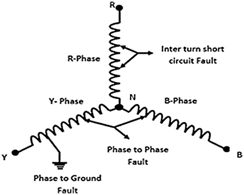
Figure 1: Stator winding faults [8]
Stator inter-turn faults will generate harmonic frequencies in the stator current of the motor that can be described as [5,13]:
where, p is the number of pole pairs, n = 1,2,3,…., and k = 1,3,5……, etc.
Model-based, signal processing and Deep Learning (DL) are the main fault detection approaches presently used in induction motors [14]. Vibration, current, stray flux, air-gap flux, voltage, power, temperature, acoustics, and partial discharge are all quantities that have been used in fault detection. Of these, noninvasive current measurement using current sensors in the time domain is a straightforward approach in which current can be measured at any point. Current measuring sensors are simple to install, provide rich information for fault detection, and can be a good alternative to vibration [15]. Motor current can be measured and analyzed in either transient or steady-state modes (or both).
Two common approaches to the steady-state analyses of stator current involve monitoring the negative sequence current arising from imbalances between the motor phases and performing Motor Current Signature Analysis (MCSA) [16] in the frequency domain. MCSA is the most widely adopted and reliable technique to detect and identify the frequency components appearing in the current spectrum of a faulty motor. Typically, the current is measured in the time domain and converted to the frequency domain to identify the fault frequencies. While Fast Fourier transform (FFT), short-time Fourier transform (STFT), and Wavelet Transform (WT) are commonly used in MCSA-based fault diagnosis, each has their own drawbacks. For example, motor current data are often non-stationary, and FFT techniques tend to obscure spectral changes over time. Similarly, the STFT based spectrogram S(t, f) in Eq. (2), below, describes the squared magnitude of the signal energy representing the time and frequency of the original signal x(t) windowed by w(t) [17]. STFT therefore provides (t, f) information with a fixed-sized window but provides poor frequency resolution [15].
To overcome the issue of poor frequency resolution and window size, many researchers have used wavelet transform analysis in both its discrete and continuous forms. Wavelet techniques detect time-frequency information in the signal without needing to adjust window size and thus offer more detailed fault information than other methods [16]. The Continuous Wavelet Transform (CWT) produces a spectrum of time-scale versus amplitude called a scalogram, which can be used to achieve better time localization for short-duration, high-frequency events, and better frequency localization for low-frequency, longer-duration events. Signal energy is also preserved by the scalogram which is the square of the absolute value of the signals plotted as a function of time and frequency [17]. Both STFT based spectrogram and CWT-based scalogram methods have been used effectively to identify time-frequency features of induction motor signals in various conditions. Acquired time-domain current data in alternative healthy and unhealthy conditions can be analyzed using conventional signal analysis tools (e.g., MATLAB) by taking the STFT based spectrogram and CWT-based scalogram and adjusting the percentage overlap, spectral leakage, window size with shape factor, time-bandwidth (TBW), and voices per octave. The scale resolution becomes finer with a rise in the number of voices per octave.
Deep Learning (DL) as a sub-domain of artificial intelligence that has been widely applied to the analysis and diagnosis of industrial systems. Its capabilities, such as high generalization power, end-to-end implementation and noise tolerance, have boosted its applications in various domains such as the automotive industry, chemical industry, agriculture, and healthcare industry [18–21]. DL has already been employed for condition diagnosis of induction motors in various industrial applications [6,22], as well as the testing of major components such as bearings and winding [22–24] and can easily distinguish between various motor conditions using a range of input signatures such as current, voltage, or vibration. Compared to signal processing techniques, they have many advantages such as high accuracy, noise tolerance, and easy upgradability [25–28]. Therefore, these methods are receiving the attention of researchers for fault detection and identification in various industrial systems such as induction motors.
Recently, researchers have employed current signatures to diagnose various IM faults. In Konar et al. [29], the CWT and Hilbert transform (HT) has been used to analyze the frequency components present in the radial vibration signal of the IM for multiclass faults (BRB, unbalanced rotor, bowed rotor, faulty bearings, stator faults, and voltage unbalance). Using the fault feature extraction in wavelet and Hilbert Transform, the specific fault type can be effectively classified. An experimental study in Saucedo-Dorantes et al. [30] shows that the CWT-based scalogram can detect inherent feature patterns of mixed imbalance, rotor-stator contact, and crack in the rotor as multiple faults based on real vibration signals. In the analysis of Khechekhouche et al. [14], a discrete energy wavelet representation (DWER) of the stator current signal was used to show that inter-turn short circuits (ITSC) and unbalanced voltage faults generate the same harmonics but can still be separately classified due to their different FFT amplitudes.
In Priyadi et al. [31], a short circuit in the IM winding has been modeled using MATLAB Simulink. Wavelet transforms were used to diagnose the strength of specific frequency and power spectral density (PSD) patterns to indicate an unhealthy condition in the winding. In Hsueh et al. [32], the time-series data of the current signals were converted to greyscale images using an empirical wavelet transform (EWT) and, after applying deep CNN, five different bearing faults accurately classified. Rotor fault detection under transient conditions has been achieved in Gyftakis et al. [33] by identification of fault spectra on the zero-sequence current signal using STFT. The rotor fault detection methodology proposed in Garcia-Calva et al. [34], involving the spectrogram, short-time multiple signal classification (MUSIC), and short-time minimum norm is well suited to transient analysis and provides high time-frequency accuracy. In Diwatelwar et al. [35], the FFT and fuzzy logic is applied to detect short-circuited phase windings. It was reported that fuzzy logic performs better than total harmonic distortion (THD) in cases where the fault current is distorted.
In a similar way to Support Vector Machines (SVM), the Artificial Neural Network (ANN) has been shown in several studies [36] to support the pattern classification of current fault signatures. On the other hand, the use of time-frequency based CWT scalogram for stator current-based SWF detection in induction motors has been rarely reported, although the scalogram is commonly used in vibration analysis. In this work, we present the time frequency-based CWT scalogram for stator current-based stator winding faults detection in induction motors. The proposed work is simulated in MATLAB with stator winding faults and analyzed under various conditions (i.e., healthy vs. unhealthy) based on the power spectral density using FFT, STFT, and CWT-based scalogram in a steady-state condition. Three deep learning models are used to detect and classify faults types based on time domain data drawn from three-phase stator currents.
The remainder of this paper proceeds as follows. Section 2 discusses the methodology of fault detection and presents the MATLAB Simulink model. Section 3 discusses stator winding fault detection that is followed by the fault identification in Section 4. The results and discussions are presented in Section 5 followed by a conclusion and future work in Section 6.
2 Methodology and Fault Simulation
A block diagram for fault detection and identification in induction motors is shown in Fig. 2. Basically, we apply current signature data derived from a simulated 3-phase induction motor model to MCSA and DL blocks to achieve fault detection and identification.
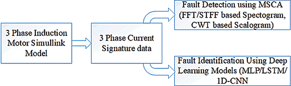
Figure 2: Methodology to detect and identify the SWFs
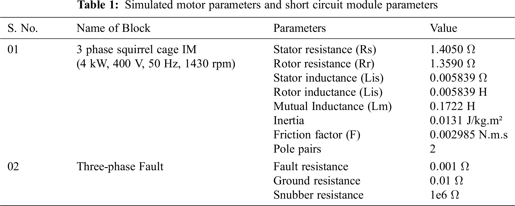
Squirrel-cage induction motors are low cost, require less maintenance, possess good efficiency during operation, and are able to maintain a constant speed. Thus, they are very commonly used in applications such as blowers, pumps, and conveyors. A simulation model of 4 kW three-phase squirrel-cage IM was developed as shown in Fig. 3. Parameters of the motor are given in Tab. 1. In this case, fault generation is achieved by simulating a three-phase short circuit to ground. The corresponding parameters are provided in Tab. 1.
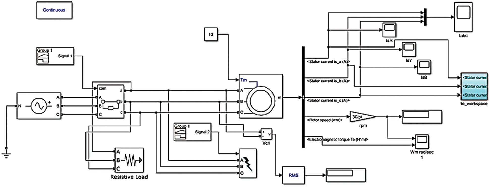
Figure 3: A simulation model for the phase to ground fault in three-phase squirrel-cage IM
3 Fault Detection Using MCSA Approach
Fig. 3 shows the methodology of a stator winding fault (phase to ground fault) detection using FFT-based spectrum, STFT-based spectrogram, and CWT-based scalogram, such that the three-phase current measurements may be analyzed within the time, frequency, and time-frequency domains. A conventional procedure for computing STFTs was used, in which the overall time signal was divided into shorter segments of equal length and the Fourier transform computed separately on each of these time windows. In contrast, the basis function (“mother” wavelet) in CWT contains both temporal and frequency components and can be scaled and shifted to correlate with the signal events, resulting in a non-uniform representation of the signal that tends to give better results in this type of analysis.
In each case, the model was simulated for one second, and faults injected at times between 350 ms and 550 ms. The three-phase current of the simulated motor was measured in the time domain and converted to the frequency domain for (t, f) analysis in the signal analyzer to identify healthy and unhealthy conditions while the phase to ground fault is applied. Differences between the healthy and unhealthy spectrograms and scalograms represent a fault detection event and the time of the fault is extracted from the data based on the energy density of the fundamental and fault frequencies due to the short circuit.
4 Fault Identification Using Deep Learning Models
In this work, we have used multilayer perceptron (MLP), long short-term memory (LSTM), and 1D-convolutional neural network (1D-CNN) deep learning models for the identification of the fault in the induction motor. These DL models are discussed in subsequent sections.
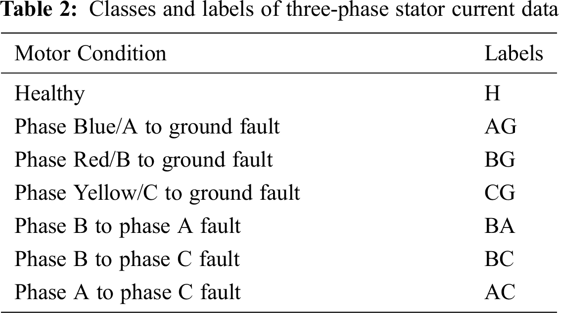
For the identification of the faults using these DL algorithms, seven categories of the phase winding healthy and unhealthy conditions have been simulated using the induction motor model shown in Fig. 3. Subsequently, time-domain information for the steady-state stator current was input to the three level learning algorithms (discussed below), which classify the induction motor condition. The time-domain data corresponds to the seven categories of the three-phase stator current data given in Tab. 2. Acquired time domain data is fed to three different DL algorithms to classify either phase to phase or phase to ground SWF occurrence. The seven categories of the time-series data include the healthy condition of the motor and SWF among the three phases of the motor, i.e. to ground or to another phase.
The hyper-parameters that are used for the models mentioned above are:
• Batch size = 256
• Number of samples = 4,00,000
• Number. of iterations = 1000
• Learning rate = 0.0001
• Data split = 70:20:10 as training data, validation data, and cross-validation data or testing data, respectively.
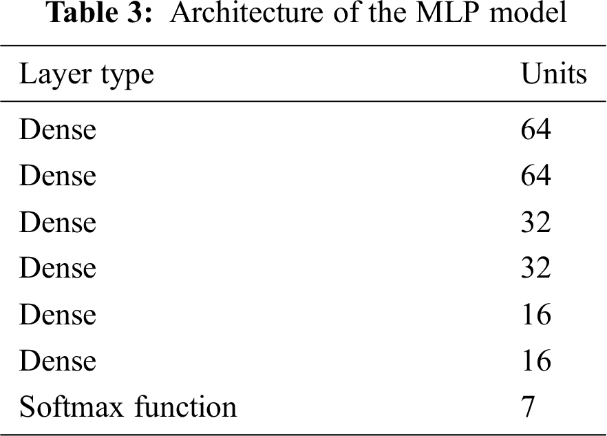
The Multi-Layer Perceptron (MLP) is a feed-forward DL model that uses a back-propagation technique for learning features from data. The model utilizes a series of hidden layers to extract complex features from input data. Here, MLP is used to classify the different conditions of IM. Tab. 3 presents the structure of the MLP model.
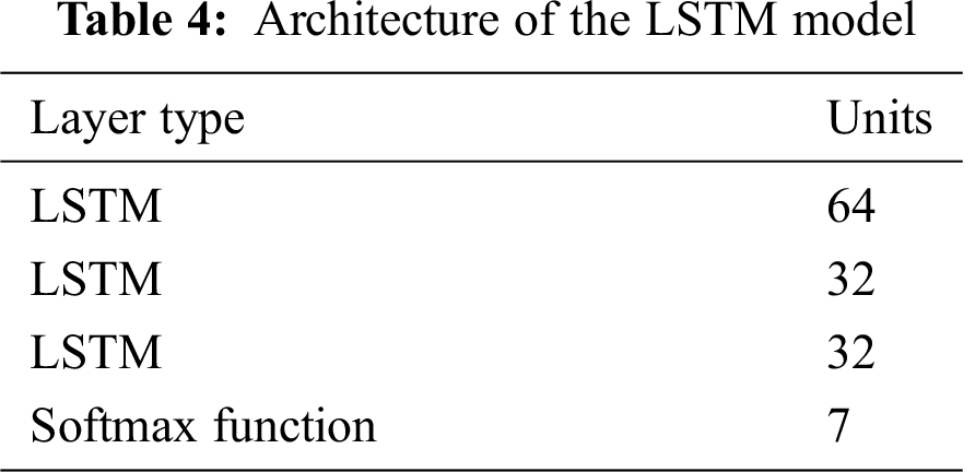
LSTM model is a modified type of RNN capable of learning long-term dependencies. It addresses the gradient vanishing problem of the RNN and offers selectivity through forgetting gates. The basic structure of the LSTM model is given in Tab. 4.
4.3 One Dimensional Convolutional Neural Network
Generally, 1D-CNN is employed for time series/sequential data analysis, which tends to slide the kernel in a single dimension. The 1D-CNN receives one-dimensional input data and yields one-dimensional output against the received input data. The structure of the 1D-CNN network employed in this work is illustrated in Tab. 5.
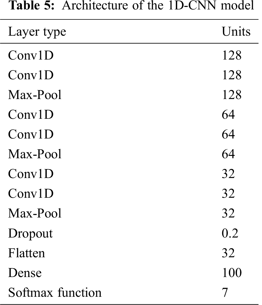
Fig. 4(a) represents the three-phase healthy stator current acquired in the time domain, showing a rise in current initially at the starting time of the motor and then remains stable for 1 s. Fig. 4(b) represents the FFT-based healthy frequency spectrum (0–300 Hz) in dB showing two peaks, one at fundamental 50 Hz, and the other one at 250 Hz. In the time-frequency domain, Figs. 4(c) and 4(d) represent the healthy time-frequency STFT based spectrogram (0–300 Hz) and the CWT based scalogram (0–256 Hz) showing a rise in signal energy of fundamental component 50 Hz at starting time and then remaining constant level for the rest of time with no additional frequency components.
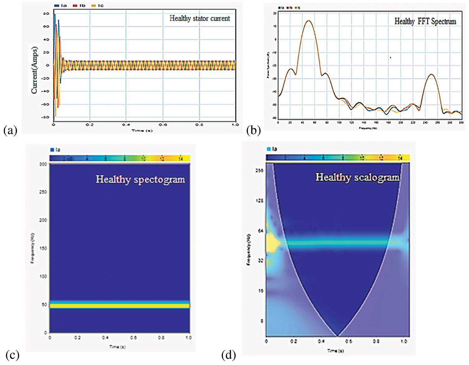
Figure 4: (a) Healthy three-phase stator current in the time domain (b) Healthy three-phase FFT-based current spectrum showing 50 Hz and 250 Hz peaks (c) Healthy STFT-based spectrogram stator current blue phase showing 50 Hz (Kaiser window), and (d) Healthy CWT-based scalogram stator current blue phase showing the only 50 Hz
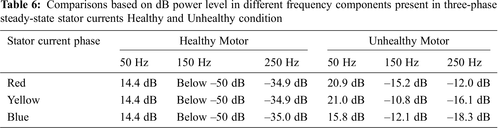
Fig. 5(a) shows a three-phase stator current of an unhealthy induction motor in the time domain, showing a rise in current between 350 ms to 550 ms. It is indistinguishable, that which phase is exposed to a fault. In the FFT-based power spectrum we can observe the rise in power at 50, 150, and 250 Hz as shown in Fig. 5(b). However, this does not indicate the time of the fault appearance. Tab. 6 contrasts the power level in dB of the fundamental 50 Hz component and other induced harmonics for the healthy condition vs. the phase short with ground.
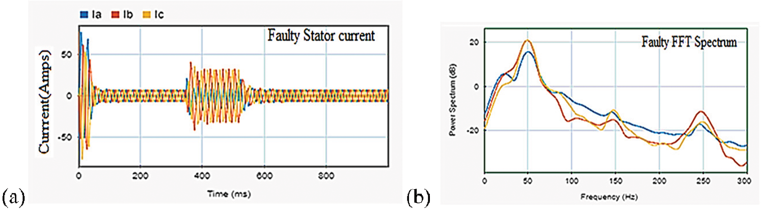
Figure 5: Unhealthy three-phase stator current (a) Time-domain, and (b) FFT-based frequency spectrum
The STFT based color-like spectrogram in Fig. 6 showing signal energy in dB provides the fault time information with frequency characteristics if the proper window size is selected. In Figs. 6(a)–6(c), STFT(t, f) based spectrogram in an unhealthy condition is shown for the range –10 to 15 dB. The color plot of signal energy is presented at the time of fault with 300 ms window size with minimum spectral leakage and 44 Hz frequency resolution for the three-phase stator current. Each 300 ms window represents the energy of the frequency spectrum in the stator current. It is evident that the window from 300 ms to 600 ms shows the rise of other frequency components apart from the fundamental 50 Hz, which is indicative of an unhealthy motor.
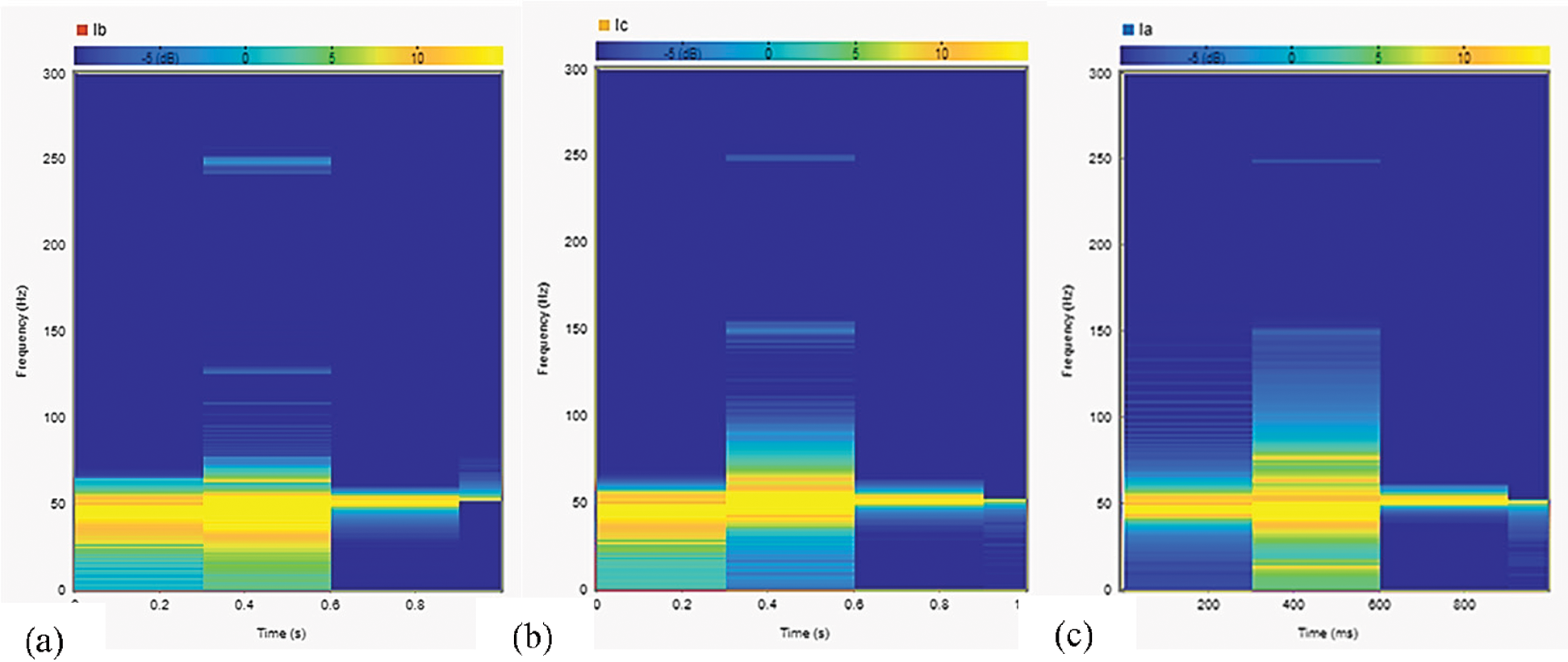
Figure 6: Showing STFT-based spectrogram of stator current in a faulty condition of (a) Red phase (b) Yellow phase, and (c) Blue phase
The fault frequencies generated due to unhealthy conditions can be observed in the CWT-based scalogram 0–15 dB range showing a color plot of signal energy by adjusting the TBW and voices per octave level. In Fig. 7, the CWT-based scalogram provides information regarding the time of occurrence of the fault by revealing the sudden change in signal energy in decibel (dB) through the color-like plot without any adjustment of window size, which is important in STFT. In Figs. 7(a)–7(c), the time-frequency domain representation of the three-phase stator current in steady-state is shown. The rise in signal energy at the fundamental component 50 Hz and other components at the time of fault can be readily observed. The intensity of the fundamental component (50 Hz) is high initially due to the motor starting. Subsequently, the 50 Hz component becomes lighter, but increases again between 350 ms to 550 ms, along with the addition of another frequency component. In a CWT-based scalogram, fault detection should be restricted to the middle of the cone as any faults detected outside of the cone may be misleading due to edge effects.
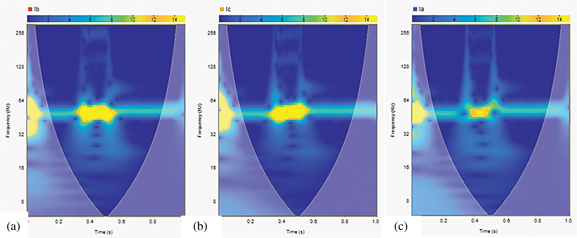
Figure 7: Showing WT-based scalogram of stator current in faulty condition (a) Red phase (b) Yellow phase, and (c) Blue phase
Fig. 9 shows the accuracy and loss graphs of the three models. All three models have demonstrated smooth performance in the training phase.
For effectively identifying the type of fault in the IM and achieving the maximum classification accuracy, all three DL models (i.e., MLP, LSTM, and 1D-CNN) were trained multiple times while varying hyper-parameters such as the number of hidden layers, number of neurons, batch size, learning rate, and optimizer. After multiple trainings, these models have yielded their best performance on the dataset. The achieved results are presented and discussed below.
Fig. 8 shows the confusion matrices of the MLP, LSTM, and 1D-CNN models. A comparison of these confusion matrices demonstrates that the LSTM model has achieved the best individual class identification performance.
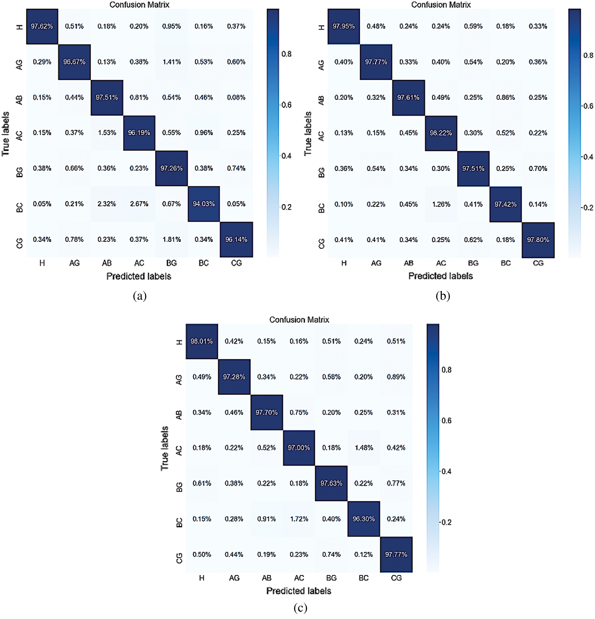
Figure 8: Confusion matrices of (a) MLP (b) LSTM, and (c) 1D-CNN
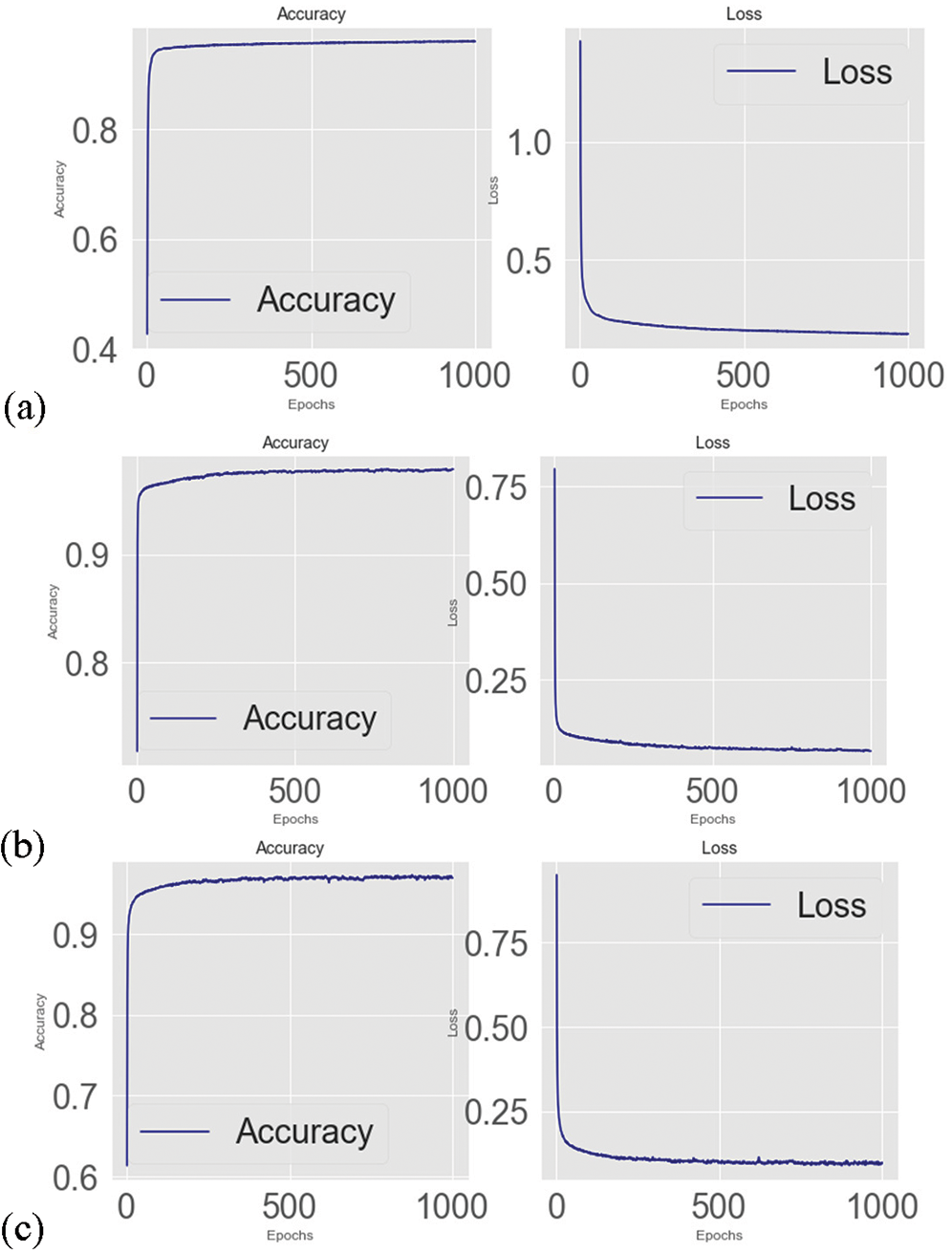
Figure 9: Accuracy and Loss diagrams of (a) MLP (b) LSTM (c) 1D-CNN
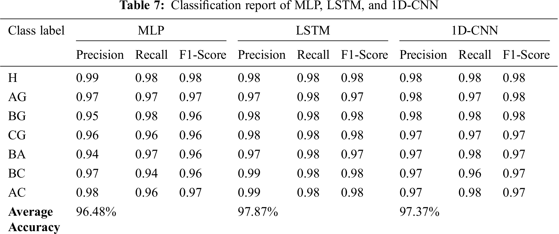
Tab. 7 shows the classification report of the three DL models. The table also confirms the superiority of the LSTM model in terms of accuracy for individual class identification. The LSTM model exhibits excellent F1 scores in the range 0.97–0.98, indicating that the classifier is able to very accurately and precisely characterize the motor behavior in both its healthy and unhealthy conditions.
In this paper, we have presented the implementation and analyses of the SWF detection and identification in a three-phase induction motor based on FFT, STFT, and CWT using three-phase stator current signatures. It is shown that MCSA can detect the changes in frequency components by obtaining the FFT-based spectrum, which provides the initial information for the fault. The time of the fault can be determined by analyzing the spectrogram, which provides the signal energy of fault frequencies with time information if the proper window size is selected. Further time-frequency analyses can be performed if fault frequencies are known. The scalogram provides the time of occurrence of a fault and its frequencies without adjusting the window size, which becomes an advantage of the CWT scalogram over the STFT spectrogram. The FFT-based spectrum, STFT-based spectrogram, and CWT-based scalogram show the changes in the frequency spectrum in all three stator currents. Three deep learning algorithms are effectively used to classify which phase winding of the IM is exposed to SWF. The proposed work shows that the MCSA approach in conjunction with DL is a reliable method to detect and identify the SWFs in a three-phase IM. Among the DL models, LSTM yielded the best classification performance compared to other models with an average accuracy of 97.87%. The proposed work also paves the way for the detection of unique frequencies present in induction motors current using Wavelet-based scalogram in other types of single or multiple fault conditions including SWF. The next step is to implement the proposed system for industrial assets management and verify the system’s accuracy and performance.
Acknowledgement: Authors would like to acknowledge the support of the ‘Haptics, Human Robotics, and Condition Monitoring Lab established in Mehran University of Engineering and Technology, Jamshoro under the umbrella of the National Center of Robotics and Automation funded by the Higher Education Commission (HEC), Pakistan.
Funding Statement: This research work is fully supported by the NCRA project of Higher Education Commission (HEC), Pakistan.
Conflicts of Interest: The authors declare that they have no conflicts of interest to report regarding the present study.
1. Y. Soufi, T. Bahi, M. Harkat and M. Mohammedi, “Fault diagnosis methods for three phase PWM inverter fed induction motor,” International Review on Modelling and Simulations, vol. 2, pp. 639–644, 2009. [Google Scholar]
2. X. Zhao, Y. Wang, Y. Zhang, J. Wu and Y. Shi, “Weak fault diagnosis of rolling bearing based on improved stochastic resonance,” Computers, Materials & Continua, vol. 64, no. 1, pp. 571–587, 2020. [Google Scholar]
3. H. Jafari and J. Poshtan, “Fault detection and isolation based on fuzzy-integral fusion approach,” IET Science, Measurement & Technology, vol. 13, no. 2, pp. 296–302, 2018. [Google Scholar]
4. D. K. Soother, J. Daudpoto and A. Shaikh, “Vibration measurement system for the low power induction motor,” Engineering Science and Technology International Research Journal, vol. 2, pp. 53–57, 2018. [Google Scholar]
5. P. Gangsar and R. Tiwari, “Comparative investigation of vibration and current monitoring for prediction of mechanical and electrical faults in induction motor based on multiclass-support vector machine algorithms,” Mechanical Systems and Signal Processing, vol. 94, no. 8, pp. 464–481, 2017. [Google Scholar]
6. D. K. Soother and J. Daudpoto, “A brief review of condition monitoring techniques for the induction motor,” Transactions of the Canadian Society for Mechanical Engineering, vol. 43, no. 4, pp. 499–508, 2019. [Google Scholar]
7. W. R. S. Osman, K. Nisar and A. M. Altrad, “Demonstrate broadband over power line network in Malaysia,” in IEEE Int. Conf. on Consumer Electronics-China, Shenzhen, China, pp. 1–6, 2014. [Google Scholar]
8. E. Karim, T. Memon and I. Hussain, “FPGA based on-line fault diagnostic of induction motors using electrical signature analysis,” International Journal of Information Technology, vol. 11, no. 1, pp. 165–169, 2019. [Google Scholar]
9. W. R. S. Osman, K. Nisar and A. M. Altrad, “Evaluation of broadband PLC technology over Malaysia’s indoor power line network,” in 2nd Int. Conf. on Electronic Design (ICEDPenang, Malaysia, pp. 275–280, 2014. [Google Scholar]
10. G. Devarajan, M. Chinnusamy and L. Kaliappan, “Detection and classification of mechanical faults of three phase induction motor via pixels analysis of thermal image and adaptive neuro-fuzzy inference system,” Journal of Ambient Intelligence and Humanized Computing, vol. 53, no. 5, pp. 1–12, 2020. [Google Scholar]
11. A. Alawady, M. Yousof, N. Azis and M. Talib, “Phase to phase fault detection of 3-phase induction motor using FRA technique,” International Journal of Power Electronics and Drive Systems, vol. 11, pp. 1241, 2020. [Google Scholar]
12. A. M. M. Altrad, W. R. S. Osman and K. Nisar, “Modelling of remote area broadband technology over low voltage power line channel,” International Journal of Computer Networks & Communications, vol. 4, no. 5, pp. 187–201, 2012. [Google Scholar]
13. K. Prakasam and S. Ramesh, “Testing and analysis of induction motor electrical faults using current signature analysis,” Circuits and Systems, vol. 7, no. 09, pp. 2651–2662, 2016. [Google Scholar]
14. A. Khechekhouche, H. Cherif, A. Benakcha, A. Menacer, S. E. Chehaidia et al., “Experimental diagnosis of inter-turns stator fault and unbalanced voltage supply in induction motor using MCSA and DWER,” Periodicals of Engineering and Natural Sciences, vol. 8, pp. 1202–1216, 2020. [Google Scholar]
15. N. Lahouasnia, M. F. Rachedi, D. Drici and S. Saad, “Load unbalance detection improvement in three-phase induction machine based on current space vector analysis,” Journal of Electrical Engineering & Technology, vol. 15, no. 1, pp. 1–12, 2020. [Google Scholar]
16. M. Hussain, A. R. Rizwan, I. H. Kalwar, D. T. Memon et al., “Multiple faults detection and identification of three phase induction motor using advanced signal processing techniques,” 3C Tecnología, Special Issue, 93–117, 2020. [Google Scholar]
17. I. Yesilyurt, “The application of the conditional moments analysis to gearbox fault detection—A comparative study using the spectrogram and scalogram,” NDT & E International, vol. 37, no. 4, pp. 309–320, 2004. [Google Scholar]
18. Y. Lei, B. Yang, X. Jiang, F. Jia, N. Li et al., “Applications of machine learning to machine fault diagnosis: A review and roadmap,” Mechanical Systems and Signal Processing, vol. 138, no. 2005, pp. 106587, 2020. [Google Scholar]
19. H. Chen and B. Jiang, “A review of fault detection and diagnosis for the traction system in high-speed trains,” IEEE Transactions on Intelligent Transportation Systems, vol. 21, no. 2, pp. 450–565, 2019. [Google Scholar]
20. Y. Luo, X. Li, C. Luo, F. Wang, X. Wu et al., “ Tissue segmentation in nasopharyngeal CT images using two stage learning,” Computers, Materials & Continua, vol. 65, no. 2, pp. 1771–1780, 2020. [Google Scholar]
21. M. Azamfar, J. Singh, I. Bravo-Imaz and J. Lee, “Multisensor data fusion for gearbox fault diagnosis using 2-D convolutional neural network and motor current signature analysis,” Mechanical Systems and Signal Processing, vol. 144, pp. 106861, 2020. [Google Scholar]
22. A. Choudhary, D. Goyal, S. L. Shimi and A. Akula, “Condition monitoring and fault diagnosis of induction motors: A review,” Archives of Computational Methods in Engineering, vol. 26, no. 4, pp. 1221–1238, 2019. [Google Scholar]
23. D. Neupane and J. Seok, “Bearing fault detection and diagnosis using Case Western Reserve University dataset with deep learning approaches: A review,” IEEE Access, vol. 8, pp. 93155–93178, 2020. [Google Scholar]
24. K. Tidriri, N. Chatti, S. Verron and T. Tiplica, “Bridging data-driven and model-based approaches for process fault diagnosis and health monitoring: A review of researches and future challenges,” Annual Reviews in Control, vol. 42, no. 8, pp. 63–81, 2016. [Google Scholar]
25. C. Morales-Perez, J. Rangel-Magdaleno, H. Peregrina-Barreto and J. Ramirez-Cortes, “Bearing fault detection on IM using MCSA and sparse representation,” in IEEE Int. Instrumentation and Measurement Technology Conf., Dubrovnik, Croatia, pp. 1–6, 2020. [Google Scholar]
26. Y. Yuan, G. Ma, C. Cheng, B. Zhou, H. Zhao et al., “A general end-to-end diagnosis framework for manufacturing systems,” National Science Review, vol. 7, no. 2, pp. 418–429, 2020. [Google Scholar]
27. M. Cerrada, R. V. Sánchez, C. Li, F. Pacheco, D. Cabrera et al., “A review on data-driven fault severity assessment in rolling bearings,” Mechanical Systems and Signal Processing, vol. 99, pp. 169–196, 2018. [Google Scholar]
28. S. M. Ujjan, I. H. Kalwar, B. S. Chowdhry, T. D. Memon and D. K. Soother, “Adhesion level identification in wheel-rail contact using deep neural networks,” 3C Technologia, Special issue, pp. 217–231, 2020. [Google Scholar]
29. P. Konar and P. Chattopadhyay, “Multi-class fault diagnosis of induction motor using Hilbert and Wavelet Transform,” Applied Soft Computing, vol. 30, no. 5, pp. 341–352, 2015. [Google Scholar]
30. J. J. Saucedo-Dorantes, M. Delgado-Prieto, R. D. J. Romero-Troncoso and R. A. Osornio-Rios, “Multiple-fault detection and identification scheme based on hierarchical self-organizing maps applied to an electric machine,” Applied Soft Computing, vol. 81, no. 3, pp. 105497, 2019. [Google Scholar]
31. A. Priyadi, Y. N. Sari, V. Jonar, D. A. Asfani and F. Andriawan, “Short circuit simulation and analysis in stator winding of three phase induction motor using wavelet transform and power spectral density,” in Conf.: ISITIA, Seminar on Intelligent Technology and Its Applications, Surabaya, Indonesia, pp. 1–4, 2014. [Google Scholar]
32. Y. M. Hsueh, V. R. Ittangihal, W. B. Wu, H. C. Chang and C. C. Kuo, “Fault diagnosis system for induction motors by CNN using empirical wavelet transform,” Symmetry, vol. 11, no. 10, pp. 1212, 2019. [Google Scholar]
33. K. N. Gyftakis, D. V. Spyropoulos and E. Mitronikas, “Advanced detection of rotor electrical faults in induction motors at start-up,” IEEE Transactions on Energy Conversion, vol. 2020, pp. 1–9, 2020. [Google Scholar]
34. T. A. Garcia-Calva, D. Morinigo-Sotelo, O. Duque-Perez, A. Garcia-Perez and R. J. Romero-Troncoso, “Time-frequency analysis based on minimum-norm spectral estimation to detect induction motor faults,” Energies, vol. 13, pp. 4102, 2020. [Google Scholar]
35. K. P. Diwatelwar and S. K. Malode, “Fault detection and analysis of three-phase induction motors using MATLAB Simulink model,” International Research Journal of Engineering and Technology, vol. 5, pp. 1643–1649, 2018. [Google Scholar]
36. A. K. Verma, S. Nagpal, A. Desai and R. Sudha, “An efficient neural-network model for real-time fault detection in industrial machine,” Neural Computing and Applications, vol. 33, pp. 1–14, 2020. [Google Scholar]
 | This work is licensed under a Creative Commons Attribution 4.0 International License, which permits unrestricted use, distribution, and reproduction in any medium, provided the original work is properly cited. |