DOI:10.32604/iasc.2021.015274
| Intelligent Automation & Soft Computing DOI:10.32604/iasc.2021.015274 | |
| Article |
Implementation of Multi-Object Recognition System for the Blind
Department of IT Engineering, Sookmyung Women’s University, Seoul, 04310, Korea
*Corresponding Author: Jongwoo Lee. Email: bigrain@sm.ac.kr
Received: 13 November 2020; Accepted: 23 March 2021
Abstract: Blind people are highly exposed to numerous dangers when they walk alone outside as they cannot obtain sufficient information about their surroundings. While proceeding along a crosswalk, acoustic signals are played, though such signals are often faulty or difficult to hear. The bollards can also be dangerous if they are not made with flexible materials or are located improperly. Therefore, since the blind cannot detect proper information about these obstacles while walking, their environment can prove to be dangerous. In this paper, we propose an object recognition system that allows the blind to walk safely outdoors. The proposed system can recognize obstacles and other objects through a real-time video stream and a sensor system, and provides the recognition results to the blind via a voice output. The system is able to figure out the current state of a pedestrian signal, the position of a bollard, and the direction of a tactile paving all at the same time using an object recognition module. In addition, its sensor determines whether there is an obstacle near the blind at a specific distance. We built a prototype of the object recognition system using a Raspberry Pi module, and then evaluated it with an experiment created for testing purposes, in which the system drives a programmable remote-control car. The experiment results showed that our object recognition system succeeds in detecting the obstacles and taking a safer route in order to avoid them.
Keywords: blind; obstacles; object detection; sensor; Raspberry Pi
Blind people are exposed to many risks while walking as they can only obtain limited surrounding information. Although they should benefit from using assistive transportation facilities, such facilities are often insufficient or incorrectly installed. In a 2019 survey by the Seoul Metropolitan Government, which investigated the transportation facilities for the people with disabilities in the Gangbuk region, it was shown that a total of 16,286 cases did not meet the standards. A total of 45.6% of such cases were related to acoustic signals not working or being misplaced. 23.3% of the cases were related to the bollards being made of non-elastic materials or being inconspicuous at night [1]. In another study, the blind had difficulties walking outdoors because it was difficult for them to detect obstacles above their waist or a few feet away [2]. According to [3], the number of blind and visually impaired individuals continues to grow, expecting to increase up to a115 million by 2050. Although their number is increasing rapidly, facilities to help them walk independently are still in poor condition. Many pf them use a white cane to detect obstacles; however, a white cane cannot classify what an object is, and has its limitation in providing direction guidance [4]. Some blind people receive help from guide dogs that are trained to safely guide them; however, guide dogs are expensive and require care, making them difficult to obtain and keep [5]. Therefore, information such as the status of pedestrian signals, the tactile paving placement, and the positions of obstacles is necessary for the blind to walk safely. A recent study found that there are 146 different types of mobility aids in the forms of products, systems, and devices [6], while more technologies are being developed. However, there are rooms for these technologies to be improved with new systems that can better the available aid.
In this paper, we implement a system that is capable of recognizing elements such as pedestrian signals, bollards, and tactile paving. It would allow the blind to walk safely even when alone as it would convey to them important information through a voice output, or driving commands to the car in the case of test experiment. Our system has an object recognition module that recognizes objects in a real-time camera feed using an object recognition model trained on a deep-learning technology. Thus, through the real-time camera feed, time-crucial information such as a pedestrian signal status can be determined in real-time. The system determines the pedestrian signal status through its signal discrimination module. On the other hand, the system identifies the bollards, and their position through its location calculation module. The tactile paving, is detected by the system which determines the directions using a tactile paving detection module. Lastly, the system as well, checks for any obstacles near the user with an embedded ultrasonic sensor. All the information resulting from these modules are provided to the blind via a voice output, enabling them to walk safely on their own.
Walking assistance systems have been developed as essential factors for the blind to walk on their own. Guidance and navigation systems that help them walk safely both indoors and outdoors have also been developed. Mixed reality, smartphones, and wearables are now marked as important contributors to these innovations [7,8]. Walking assistants can be classified into three categories based on key technology: sensor-based walking assistants, computer vision-based walking assistants, and smartphone-based walking assistants [9]. The sensor-based walking assistants collect information through sensors, detecting obstacles nearby and calculating the distance between each of them and the user. Most of them use an ultrasonic sensor that measures how far away a target object is by emitting ultrasonic sound waves, but some use sonar technology that obtains spatial information through auditory signals [10]. The computer vision-based walking assistants collect information through cameras, capturing images of the surroundings and recognizing obstacles in those images through diverse algorithms. One example of it is a system that detects and avoids obstacles using a depth camera [11,12]. Although the computer vision-based walking assistants cannot tell the user the distance to obstacles, they can be advantageous because they can inform their users what obstacles are. This can be very helpful because, generally, humans obtain more detailed information about their surroundings through their sight compared to their touch or auditory senses [13]. Thus, with computer vision-based walking assistants, the blind can obtain more specific visual information regarding the environment, not only knowing the presence of an obstacle ahead but also its identity. The smartphone-based walking assistants use built-in cameras and sensors, and work in similar ways as the computer vision-based assistants. One disadvantage of the computer vision-based assistants is that they can only recognize obstacles that they have been trained for. Thus, each of these walking assistants has its own strengths and weaknesses. In addition, depending on the key technology, there can be limitations such as high cost or weight.
In our previous study, we proposed an object recognition system that uses a video camera [14] to capture its surroundings real-time and provides information on the pedestrian signals and bollards in the video to a blind user. The object recognition module of this system could determine the status of the pedestrian signal every second and guide the user through a voice command using a Raspberry Pi. This system only used a camera to recognize obstacles, it could only provide information on one type of object at once. For example, if this system once detected bollards in an image frame, it could not detect other important objects such as pedestrian signals and tactile paving at the same time. In addition, its performance in discerning the status of the pedestrian signal at night was very low compared to its performance in it at day. Furthermore, this system could not recognize some important elements such as tactile paving, a textured ground surface that guides the blind in what direction to go.
3 Object Recognition System Architecture and Object Recognition Model
Our new object recognition system streams a video and collects data using the camera module and the ultrasonic sensor, which are equipped to the Raspberry Pi. It then recognizes objects through the recognition module. The system can recognize various objects that appear in the video, such as pedestrian signals, bollards, tactile paving, and people. It does so through the object detection module and the tactile paving detection module. The distance between the user and each of the recognized objects is obtained from the sensor data. The system accepts a recognized object as an obstacle only if it is under a certain distance from the user. Depending on the type of the recognized object, the pedestrian signal discrimination module, the location calculation module, or the direction finding algorithm is used to determine the current state of the pedestrian signal, the location of the bollard, or the direction of the tactile paving, respectively. The resulting information is then sent to the Raspberry Pi through a network module to provide guidance to the blind via a voice command or, in the case of our experiment, to the driving module to drive the remote-control car without manual operation.
Fig. 1 shows the architecture of the object recognition system. The system consists of a Raspberry Pi client and a server. The Raspberry Pi client is equipped with a camera and sensor modules, to get the information about the surroundings, and a voice guidance module, to provide recognized results to the blind. It is also equipped with a motor module to control the driving direction of the car in our later experiment for testing purposes. The server side contains many modules that take the information provided by the Raspberry Pi client and do the calculations to make sense of the input data. The overall process can be organized into multiple steps. First, the camera of the Raspberry Pi streams a video real-time. Then, the server receives the streamed video and divides it into 30 frames per second. The divided frames are given as input data to the object detection module and the tactile paving detection module. Meanwhile, the data collected from the ultrasonic sensor are delivered to the sensing data processing module via a data receiver on server-side. The object detection module, which has received the 30 divided image frames, recognizes various objects such as pedestrian signals, bollards, and people from each of the 30 frames. The object recognition is achievedby our object recognition model, which is an expanded version of the model provided by the Google object detection application programming interface (API). The object recognition model is further detailed in the subsequent section. When the object detection module recognizes a pedestrian signal, the part of the image that is recognized as a pedestrian signal is cropped and given as an input to the pedestrian signal discrimination module. Then, the color identification module determines the color of the signal state, and since there are 30 image frames per second, the pedestrian safety guidance module can look at all 30 color results to discern the state of the pedestrian signal for the current second. The algorithm inside the pedestrian safety guidance module is further detailed in section 4.1. When the object detection module recognizes a bollard, it determines whether the bollard is located on the left or the right side of the image by marking its position with coordinates. Meanwhile, the tactile paving detection module recognizes the yellow tactile paving by using a color function and determines whether the tactile paving is straight-forward or changing directions by applying the direction-finding algorithm. Lastly, the sensing data processing module uses the data obtained through the ultrasonic sensor to calculate the distance between the user and any obstacle ahead. The location calculation module then identifies the location(s) of the obstacle(s) by using the calculated distance.
The recognized results from the three modules are then sent to the Raspberry Pi client. The voice guidance module alerts the blind through a voice channel if it recognizes an obstacle ahead. In the case of our test experiment, the result from the object recognition module is given as input to the driving module, which uses the data to control the programmable remote-control car. The driving module consists of several algorithms that aid in forming the driving instructions for the car. The localization algorithm determines the obstacles’ locations by measuring the distance between the car and each of the obstacles. The sidewalk recognition algorithm determines whether the car is on the sidewalk or not by looking at the car’s position relative to the curb. The obstacle avoidance algorithm enables the car to avoid the recognized obstacles as it moves. Thus, these integrated results are used to form driving instructions for the car so that it can avoid obstacles. The driving instructions are then sent to the controlling motor module inside the Raspberry Pi client via the driving instruction sender, so that the controlling motor module can make the car move. Therefore, the various information given by the object recognition module enables the car to move and avoid obstacles automatically.
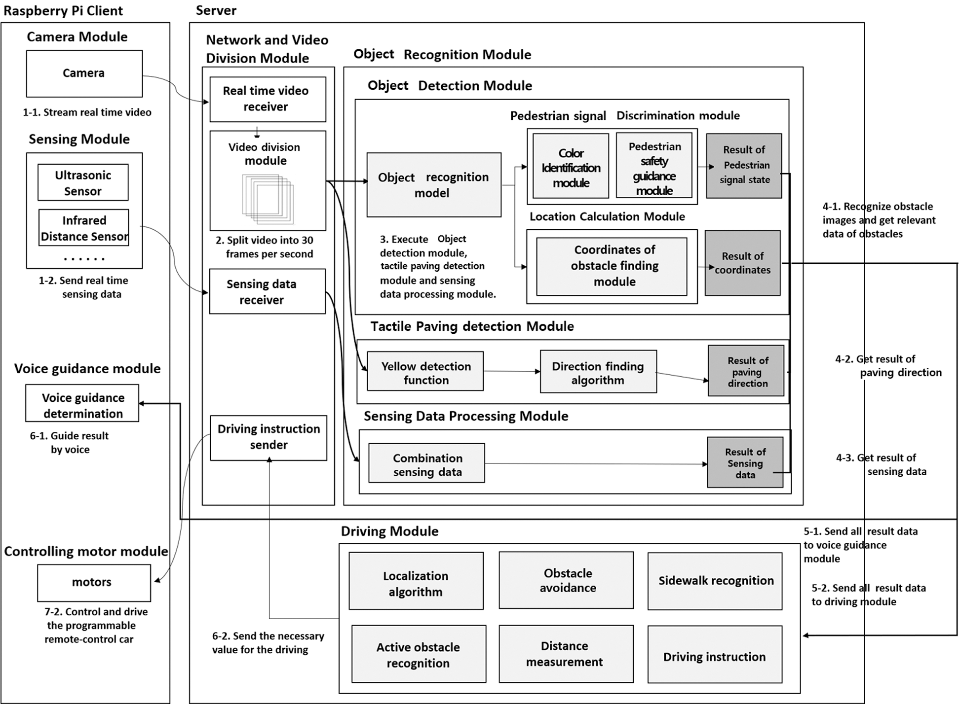
Figure 1: Architecture of the object recognition system
Our system uses the model from the Google object detection API that is further-trained on deep-learning technology [15] to recognize obstacles from the video stream. The name of the model from the Google object detection API is Faster_R-CNN_ResNet101_COCO model [16], and this model achieves a high recognition performance for 90 different classes of common objects such as people and cars. We chose this model as the base model because this model can be applied with small computing power. The model needed further training because it had very little to no recognition rate for important objects like pedestrian signals and bollards. Thus, we improved the model by training it additionally on a newly-collected image data: images of pedestrian signals and bollards taken from various backgrounds and locations. The pedestrian signal image data included images of all three states that the signal can be in: red, green, and blinking green. We also made sure that there were images from both day and night. We used the LabelImg [17], a tool that generates a data file containing the coordinates of objects in an image in extensible markup language (XML) format, to mark the coordinates of each object in the image prior to training the model. Each image was paired with a cropped version of itself that only contained the target object. A total of 10,100 pairs of such image data were used for training our previous model, and 1,000 pairs of data were used as test data. When training the model, the number of steps was 50,000 and the input image size had a pixel resolution of 500 × 500. The further training enabled our model to achieve high recognition performance for all necessary objects and thus be used by the object detection module to recognize these objects.
The state of the pedestrian signal and the information regarding other objects like bollards and tactile paving are determined by the process shown in Fig. 1. Fig. 2 shows the hierarchical structure of the modules developed in this paper. The pedestrian signal discrimination module, location calculation module, and tactile paving detection module use data obtained through the video stream, while the sensing data processing module uses data obtained through the ultrasonic sensor. These four central modules are executed simultaneously, enabling the system to obtain information about many obstacles in a frame at the same time.

Figure 2: Structure of modules
4.1 Pedestrian Signal Discrimination Module
When a pedestrian signal is recognized by the object recognition model, the current state of the pedestrian signal is determined by the pedestrian signal discrimination module. Fig. 3 shows the algorithm used for pedestrian signal discrimination [18]. The obstacle recognition model first crops the part of the image recognized as the pedestrian signal and extracts it as a separate image. The pedestrian signal discrimination module determines whether the signal is lighted red or green by using the color identification module. The system from the previous study [14] determines the color of the pedestrian signal by checking the color composition of the extracted image and concluding that it is red if it detects more than 1% of red from the extracted image, and green if it detects more than 1% of green. Its performance is low because the cropped images are likely to include some of the environment surrounding the pedestrian signal, which contains red and green colors that can confuse the system. Thus, a new color identification rule is created for the new system, consisting of different, improved settings generated by further analysis of more pedestrian signal images. The further analysis shows that the recognition rate would be optimized if more than 10% of the color has to be detected from the cropped image for it to be recognized as the color of the pedestrian signal. In addition, the optimal percentage threshold for color detection is different for the daytime and the nighttime, because of the lens flare being worse at night. For nighttime, it is optimal if more than 50% of the color has to be detected from the image. Therefore, in the new color identification rule, the threshold for determining the pedestrian signal color is set as 10% for daytime images and 50% for nighttime images, improving the performance of the color identification module.
After figuring out the signal color per image frame, the color identification module converts each frame to characters “r,” “g,” and “b” for “red,” “green,” and “blinking-green” respectively. Since the video division module divides the video input into 30 frames per second, the signal state per second can be determined with greater accuracy as the abundance of frames allows a few anomalies caused by a few incorrect results from the pedestrian signal discrimination module to be filtered out. The technique used to determine the signal state of the current second is called the “new signal-status string technique.” Using this technique, the pedestrian signal discrimination module compares the character of the new input frame and the current signal status string and finds a pattern between them. It filters out some characters that are highly different from others by generating a signal status string. Thus, we can reduce the influence of some incorrectly discriminated results in the overall discrimination result per second with this algorithm. For example, if the generated signal status string contains “bg” or “gb,” it is determined as “blinking,” and if it contains consecutive g’s, it is determined as “green.” If it contains many r’s in a row, it is determined as “red.” The determined result is sent to the Raspberry Pi client so that it can provide an appropriate voice guidance to the user or, in the case of our experiment, an input to the driving module. With this process, the assistant system can inform its user to cross the crosswalk only when the signal state is “green,” meaning that the signal is non-blinking green at the current moment with plenty of time left for the user to cross the road.

Figure 3: Algorithm for pedestrian signal discrimination
4.2 Location Calculation Module
When the object recognition model recognizes a bollard in the image, the location calculation module determines its location. First, it outlines the recognized bollard with a rectangle, and marks the two diagonally opposite points of the rectangle with coordinates. It compares the center point of the image and the center point of the rectangle to determine the location of the bollard. If the x-value of the rectangle center point is smaller than the x-value of the image center point, the system determines that the bollard is located to the left of the user. If the x-value of the rectangle center point is greater than the x-value of the image center point, the system determines that the bollard is located to the right of the user. Unlike the system from the previous study [14], the determined result is transmitted to the Raspberry Pi rather than an Android device to provide a voice output to inform the user about the bollards or, in the case of our test experiment, a set of driving instructions for the car to drive safely.
4.3 Tactile Paving Detection Module
The tactile paving detection module recognizes the tactile paving in an image and determines its course. Fig. 4 shows the algorithm used to recognize the tactile paving and determine its direction. The tactile paving detection module searches for and outlines the tactile paving by masking out the non-yellow part from the image, singling out the paving. It then marks the paving’s outlined area with a rectangular bounding box through which its width and center point can be calculated. The module uses the width of the outlined area to determine whether the paving is straight or turning. If tactile paving is turning or branching out, its outlined area tends to be wider than ones that are straight, and the center point more inclined. Thus, the module determines that a paving is turning if its outlined area is wider than a standard paving, and straight if its outlined area is narrower than the width of a turning paving but wider than the minimum paving width. If it is determined that the paving is turning, the tactile paving detection module compares the center point of its outlined area with the left point. If the center point value of the outlined area is lower than the left point, the module determines that the paving is turning to the left. If it is higher than the right point, then the module determines that it is turning to the right. The determined direction of the tactile paving is sent to the Raspberry Pi client to provide a directional guidance to the user via a voice output or to the remote-control car via the driving module.

Figure 4: Algorithm for tactile paving detection
4.4 Sensing Data Processing Module
The sensing data processing module recognizes obstacles through the ultrasonic sensor attached to the Raspberry Pi. The ultrasonic sensor can determine the presence of an obstacle by calculating the distance between the user and the obstacle ahead. The distance data determines whether an object ahead is close enough to the user, and if it is, the module considers it as an obstacle. When the module detects an obstacle, the data is transmitted to the Raspberry Pi, allowing the blind to know that there is an obstacle nearby through a voice guidance. The module also collects other necessary data such as the relative locations of the obstacles so that it can figure out what direction to go in order to avoid the obstacle. In the case of our test experiment, all collected data are transmitted to the driving module so that the programmable remote-control car can avoid obstacles as it moves.
5 Implementation Results and Performance Evaluation
In this section, we describe the prototype implementation and performance evaluation results of the object recognition system proposed in this paper. A screen showing the results of object recognition done by the object recognition model and the driving results obtained by the sensing data processing module and tactile paving detection module is presented. The signal discrimination evaluation results of the pedestrian signal discrimination module and the bollard recognition accuracy are also presented. All images and videos used for implementation and evaluation were newly taken and were not used in the model training.
5.1.1 Implementation Results of the Object Recognition Module
This section illustrates the result of using the object recognition module. The result screen displays information about each of the objects in the image, featuring the blue center point of the tactile paving and the rectangular outlines of other recognizable objects such as pedestrian signals, bollards, people, and vehicles. Fig. 5 shows the results of various objects being recognized. Recognizing pedestrian signals and bollards is made possible through our additionally trained version of the Google object detection API model. People and buses are the two out of the 90 common objects that the original Google model can recognize without additional training. As explained previously, each of the recognized objects is marked with a bounding box so that its position in the frame can be easily known.

Figure 5: Screen recognizing object using our object recognition model
5.1.2 Implementation Results of Driving Performance
To implement a prototype of our system, we set up a driving experiment with a programmable remote-control car. We had two test cases, one for testing the sensing data processing module and one for testing the tactile paving detection module. Fig. 6 shows the remote-control car recognizing the wall and avoiding it using the data from the ultrasonic sensor. The left side of the figure displays the results of the distance measuring done by the ultrasonic sensor, while the right side displays the car moving based on those results. First, the distance between the obstacle ahead and the car is continuously measured by the ultrasonic sensor. If the measured distance becomes less than 20cm, it recognizes that the wall in front is an obstacle. Thus, an “obstacle detected” string is given as the output, making the car stop. The car then moves back slightly and turns right to avoid the wall, continuing its journey, while the module goes back to measuring the distance between the car and any object ahead to search for obstacles.

Figure 6: Driving performance using the ultrasonic sensor
Fig. 7 shows the car recognizing a tactile paving that is turning to the right, and driving along the direction of the tactile paving. The left side of the figure shows the screen with a blue point marked at the center point of the detected tactile paving, while the right side shows the car’s movement. First, the system recognizes the tactile paving, and determines that it is turning right by looking at its center point. The car receives the resulting string “right” from the driving module, and so turns right when it reaches the corner of the paving. Finally, since the rest of the paving goes straight forward, the car drives straight until it receives a new result from the server.

Figure 7: Driving performance of system when a tactile paving is detected
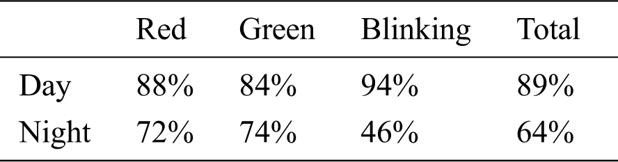
We evaluated the performance of the pedestrian signal discrimination module, which determines the status of the pedestrian signal. The evaluation system recognizes the pedestrian signal in the video stream and checks whether the status of the recognized signal is correctly determined. We used newly recorded videos for the evaluation. 150 videos each were recorded for day and night, and out of those 150, 50 each were recorded for the three states that the signal can be in: red, green, and blinking-green. Thus, a total of 300 videos were recorded, and each of the videos had a duration of 5 seconds. Tab. 1 shows the performance evaluation results. Among the 150 videos taken during the day, 44 red, 42 green, and 47 blinking-green cases were correctly determined. Among the 150 videos taken during the night, 36 red, 37 green, and 23 blinking-green cases were correctly determined. The results show a poor recognition performance for the blinking-green case at night because the light flare becomes very prominent in the nighttime, making the signal light more difficult to discern at night.
Table 1: Accuracy measurement of the pedestrian signal discrimination module
We also evaluated the system’s recognition accuracy regarding bollards. 500 bollard images were collected as test data, all of which were different from the training data. The system correctly recognized the bollards in 462 images out of the 500, making the bollard recognition rate 92.4%.
In this study, we propose an object recognition system for helping the blind walk safely outdoors. The proposed system collects data using a real-time video stream from a Raspberry Pi and an ultrasonic sensor. The information regarding the obstacles is successfully identified within the collected image data, and is sent to the Raspberry Pi.
The proposed system uses the Faster R-CNN model with additional training to better recognize obstacles in the video. Among common objects in the street, the pedestrian signals and the bollards are especially important to the blind while walking. The real-time state of the pedestrian signal and the position of the bollard are determined through the pedestrian signal discrimination module and the location calculation module, respectively. As shown in the performance evaluation, the pedestrian signal discrimination module displays 89% recognition accuracy in the daytime and 64% at night. The tactile paving detection module also successfully recognizes tactile pavings, which provide directional guidance to the blind. The sensing data processing module recognizes obstacles by measuring the distance between the user and the obstacle ahead through the ultrasonic sensor. The recognized and determined results are sent to the Raspberry Pi client to provide voice guidance to the blind, helping them walk safely even when alone.
For future research, we plan to propose a system that provides information on sidewalk boundaries and other obstacles such as power poles, garbage cans, and buildings. We will use object recognition models and a variety of sensors such as infrared and lidar sensors to recognize these various objects. We will also conduct a test experiment where a driving module will enable a wheelchair to move without manual manipulation using the information gained by the object recognition system. These developments will allow the system to help a more diverse types of users and better aid them in walking outdoors safely.
Funding Statement:This work was supported by the National Research Foundation of Korea (NRF) funded by the MSIT(NRF-2018R1A4A1025559). This research was supported by stage 4 BK21 project in Sookmyung Women’s Univ of the National Research Foundation of Korea Grant.
Conflicts of Interest:The authors declare that they have no conflicts of interest to report regarding the present study.
1. DongA Ilbo. (2020. 3. 19) The disabled walks directly to find the inconvenience in Gangnam Area. [Online]. Available: https://www.donga.com/news/Society/article/all/20200319/100227522/1. [Google Scholar]
2. M. Bousbia-Salah, M. Bettayeb and A. Larbi, “A navigation aid for blind people,” Journal of Intelligent & Robotic Systems, vol. 64, no. 3-4, pp. 387–400, 2011. [Google Scholar]
3. R. Bourne, S. Flaxman, T. Braithwaite, M. Cicinelli, A. Das et al., “Magnitude, temporal trends, and projections of the global prevalence of blindness and distance and near vision impairment: A systematic review and meta-analysis,” Lancet Global Health, vol. 5, no. 9, pp. 888–897, 2017. [Google Scholar]
4. Y. Shiizu, Y. Hirahara, K. Yanashima and K. Magatani, “The development of a white cane which navigates the visually impaired,” in Proc. Annual Int. Conf. of the IEEE Engineering in Medicine and Biology Society (EMBCLyon, France, pp. 5005–5008, 2007. [Google Scholar]
5. R. Jafri, R. Campos, S. Ali and H. Arabnia, “Visual and infrared sensor data-based obstacle detection for the visually impaired using the Google Project Tango tablet development kit and the Unity engine,” IEEE Access, vol. 6, pp. 443–454, 2017. [Google Scholar]
6. U. Roentgen, G. Gelderblom, M. Soede and L. Witte, “Inventory of electronic mobility aids for persons with visual impairments: A literature review,” Journal of Visual Impairment & Blindness, vol. 102, no. 11, pp. 702–724, 2008. [Google Scholar]
7. S. Real and A. Araujo, “Navigation systems for the blind and visually impaired: Past work, challenges, and open problems,” Sensors, vol. 19, no. 15, pp. 3404, 2019. [Google Scholar]
8. A. Ramadhan, “Wearable smart system for visually impaired people,” Sensors, vol. 18, no. 3, pp. 843, 2018. [Google Scholar]
9. M. Islam, M. Sadi, K. Zamli and M. Ahmed, “Developing walking assistants for visually impaired people: A review,” IEEE Sensors Journal, vol. 19, no. 8, pp. 2814–2828, 2019. [Google Scholar]
10. B. Laurent and T. Christian, “A sonar system modeled after spatial hearing and echolocating bats for blind mobility aid,” Int. Journal of Physical Sciences, vol. 2, no. 4, pp. 104–111, 2007. [Google Scholar]
11. M. Brock and P. Kristensson, “Supporting blind navigation using depth sensing and sonification,” in Proc. the 2013 ACM Conf. on Pervasive and Ubiquitous Computing Adjunct Publication, Zuich, Swizerland, pp. 255–258, 2013. [Google Scholar]
12. H. Pham, T. Le and N. Vuillerme, “Real-time obstacle detection system in indoor environment for the visually impaired using Microsoft Kinect sensor,” Journal of Sensors, vol. 2016, no. 11, pp. 1–13, 2016. [Google Scholar]
13. J. Terven, J. Salas and B. Raducanu, “New opportunities for computer vision-based assistive technology systems for the visually impaired,” Computer, vol. 47, no. 4, pp. 52–58, 2014. [Google Scholar]
14. S. Ou, H. Park and J. Lee, “Implementation of an object recognition system for the blind,” Applied Sciences, vol. 10, no. 1, pp. 1–12, 2020. [Google Scholar]
15. Google Object Detection (2021). [Online]. Available: https://github.com/tensorflow/models/tree/master/research/object_detection. [Google Scholar]
16. Faster_R_CNN_ResNet101_COCO (2020). [Online]. Available: https://github.com/tensorflow/models/blob/master/research/object_detection/g3doc/tf1_detection_zoo.md. [Google Scholar]
17. LabelImg (2021). [Online]. Available: https://github.com/tzutalin/labelImg. [Google Scholar]
18. H. Park and J. Lee, “Improving crosswalk signal recognition for the safety of the visually impaired,” in Proc. KIISE Korea Computer Congress 2020, pp. 1339–1341, 2020. [Google Scholar]
 | This work is licensed under a Creative Commons Attribution 4.0 International License, which permits unrestricted use, distribution, and reproduction in any medium, provided the original work is properly cited. |