DOI:10.32604/iasc.2021.015482
| Intelligent Automation & Soft Computing DOI:10.32604/iasc.2021.015482 | |
| Article |
Computer Vision Based Robotic Arm Controlled Using Interactive GUI
1Department of Electrical and Computer Engineering, North South University, Bashundhara, Dhaka-1229, Bangladesh
2Department of Computer Science, College of Computers and Information Technology, Taif University, P.O. Box 11099, Taif 21944, Saudi Arabia
*Corresponding Author: Mohammad Monirujjaman Khan. Email: monirujjaman.khan@northsouth.edu
Received: 24 November 2020; Accepted: 19 December 2020
Abstract: This paper presents the design and implementation of a robotic vision system operated using an interactive Graphical User Interface (GUI) application. As robotics continue to become a more integral part of the industrial complex, there is a need for automated systems that require minimal to no user training to operate. With this motivation in mind, the system is designed so that a beginner user can operate the device with very little instruction. The application allows users to determine their desired object, which will be picked up and placed by a robotic arm into the target location. The application allows users to filter objects based on color, shape, and size. The filtering along the three parameters is done by employing a Hue-Saturation-Value (HSV) mode color detection algorithm, shape detection algorithm, size determining algorithm. Once the target object is identified, a centroid detection algorithm is employed to find the object’s center coordinates. An inverse kinematic algorithm is used to ascertain the robotic arm’s joint positions for picking the object. The arm then goes through a set of preset positions to pick up the object, place the object, and then return the arm to the initial position. The joint coordinates are forwarded to a microcontroller that sets the arm’s joint angle at each position.
Keywords: Application design; computer vision; Human Computer Interaction (HCI); inverse kinematics; microcontroller; robotics
Automation has been introduced in nearly every aspect of human life. From industrial robots to garage door openers, automation is used to reduce labor, increase efficiency, and lower cost. The term automation came into use initially in the 1940s when the Ford motor company introduced an automation department. Automation has continued to gain a larger foothold globally as advances in sensors and processing continuously present more opportunities to automate.
The most special form of automation employed today is robotic systems. Robots were first introduced onto the factory floor in the 1960s and early 1970s before rising to prominence in the 1980s as robotic systems proliferated the manufacturing world, most prominently in the automotive industry. The most widely used form of robotics in the industrial sphere in the serial manipulator or the form is colloquially known as the robotic arm. The serial manipulator consists of a series of links connected by motorized joints that connect a base to an end effector. Robotic arms are used for numerous industrial operations, which are picked and place activities as in Hao et al. [1,2], spot and arc welding as in Weman [3,4], painting [5,6], and many other uses such as in Beasley [7–12]. Robotic arms are not homogenous and are implemented in different sizes and forms [13–18] to accomplish tasks. The systems above are controlled via a combination of sensors and hardcoded instruction sets.
A robotic system may use numerous sensors including temperature, infrared, color, mass, numerous sensors, including temperature, infrared, color, mass, etc. However, a trend has developed to replace all of these sensors with a singular camera and computer vision to accomplish the task alone. Computer vision allows a computer to see and interpret the world and identify objects [19,20] using techniques like contouring or machine learning. Computer vision-based control system may be used to operate a robotic arm system to carry out complex tasks such as sorting, filtering, and pick and place without human intervention. Several systems, such as the one described above, have been implemented in the systems described in Abbood et al. [21–26].
Abbood et al. [21], the authors have employed a computer vision algorithm that can classify objects based on color and shape and then perform pick and place operation using preset positions that are hardcoded. The authors of Divya et al. [22] have designed a system that performs color sorting, and the robotic arm is manipulated in the same manner using hardcoded positions. [24,26] both perform color sorting using a color sensor and pick and place operation using presets, but Panie et al. [26] adds a simple control interface for remote operation. In Thike et al. [27], the authors employ a system that uses both a camera and a color sensor in order to achieve the goal of sorting. A camera is used in order to ascertain the color of the target object. The object is then picked up and placed in buckets which have color sensors placed underneath them so that the color of the object matches that of the bucket. In Magadum et al. [28], the authors develop a system where a robotic arm and conveyor belt system is designed. A robotic arm is used in order to place objects onto the conveyor belt, then a color sensor is used in order to ascertain the color of the object and then the object is sorted into the desired drop point. In Dewi et al. [29], the authors have designed a system in which a machine vision-based system is employed in order to determine the color and size of fruits to be picked and placed by the robotic arm. This system gives a specific possible industrial implementation for the system we are putting forward in this paper.
The above systems all use the advantages provided by automation, which include increased efficiency, time saving, etc. However, these systems also fall prey to one of the primary disadvantages of robotic systems, which is lack of flexibility. The systems can filter according to one or two parameters; however, the parameters are fixed unless someone goes into the codebase and changes the selection parameters. Furthermore, all of the systems use preset joint angles to set the position of the robotic arm. This further reduces the flexibility of the system where the position of the object to be picked up and placed must be exact, or the system fails.
This paper presents a computer vision-based robotic arm system designed for flexibility of operation with these shortcomings in mind. A four-degree freedom robotic arm system has been implemented that can be controlled via a user-friendly interface. Objects can be placed anywhere underneath the camera, and then objects can be sorted according to shape, color, and size. Furthermore, an inverse kinematic algorithm is implemented to remove the need for hard hard-coded positions, increasing the system’s positional flexibility. The remaining sections of this paper highlight the methods and materials used to design and construct the system; the results achieved; finally concludes in Section 4.
This section discusses the methods and materials that are used in order to accomplish the goal. The aim of this system is to implement a robotic arm system in which a novice operator can easily set operation parameters for the system. The first subsection puts forward a basic block diagram of the system; afterwards, we will highlight the design of the object sorting algorithms; the design of the graphical user interface; hardware implementation of the system including the cost breakdown; finally, the mathematical modeling for the inverse kinematic analysis of the system and the centroid localization will also be elaborated.
A block diagram outlining the full system is shown in Fig. 1. The system consists of the video capture, which shows the objects placed on the workspace of the robotic arm. Then, in the user interface, the operator can set the parameters. After this, three sorting algorithms are applied chronologically for color, shape, and size. The operator can see the target object highlighted in the interface and then choose to engage the robotic arm.

Figure 1: Full system block diagram showing the process by which the system accomplishes pick and place activity
To create a computer vision sorting system for our robotic system, we used OpenCV. To identify objects, the technique to be used is contouring. Contouring is a computer vision technique that simply joins all continuous points of the same color and intensity. By applying this technique, we can identify objects based on color, shape, and size without using multiple techniques for each parameter. Instead, we can carry out the selection by simply classifying the contour. The process of identifying objects based on our three parameters are elaborated in further detail in this subsection. The block diagram shown in Fig. 2 demonstrates the flow of the color sorting algorithm used for our design.
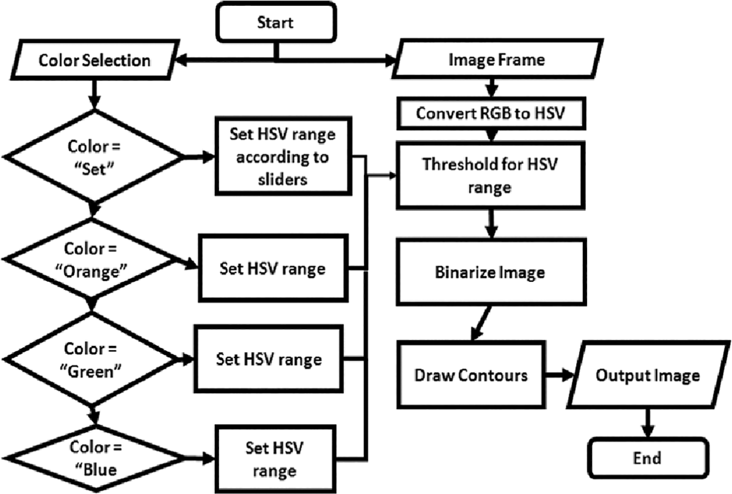
Figure 2: The flowchart demonstrates the algorithm used in order to sort objects according to color using HSV color space
The images captured by the camera are in the Red, Green, and Blue (RGB) color space and must be converted to the HSV color space to sort by color because the HSV space allows for more precise color selection. Once converted to HSV, the image is binarized such that the desired color is assigned a value of one, and the remainder of the image is assigned a value of 0, and then a contour can be drawn about the desired object. After color selection, the object is sorted according to shape. The flowchart given in Fig. 3 summarizes the process of shape sorting.
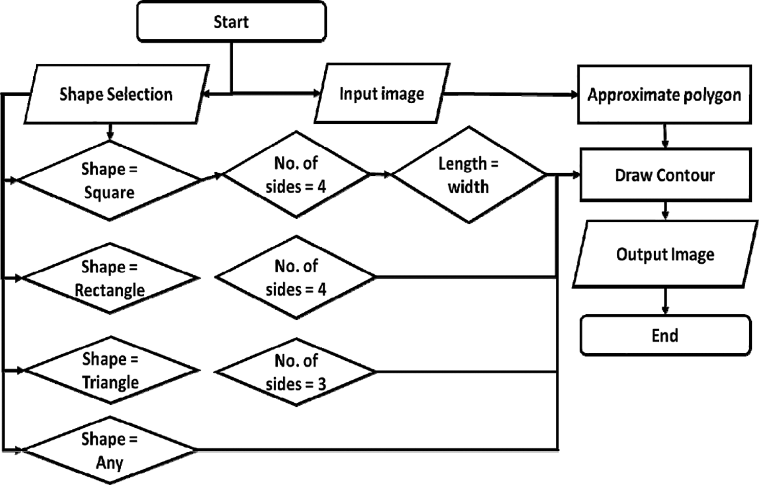
Figure 3: Flowchart demonstrating algorithm used in order to sort objects according to shape by approximating polygon to objects placed in the workspace
To sort according to shape, we categorize the contour created during color sorting. Three easily distinguishable shapes are selected as our valid possibilities. These shapes are square, triangle, and rectangle as these shapes are easily recognized, but any shape may have been chosen. A polygon is approximated to the contour. The approximated polygon features are compared to our specified features to ascertain whether an object is of the desired shape. To accomplish size sorting, we created an algorithm in accordance with Fig. 4. To ascertain the size of objects, the operator chooses one of the four sizes they are selecting for. The area constrained within the contour is compared to the selected size to ascertain if an object complies with the user selection.
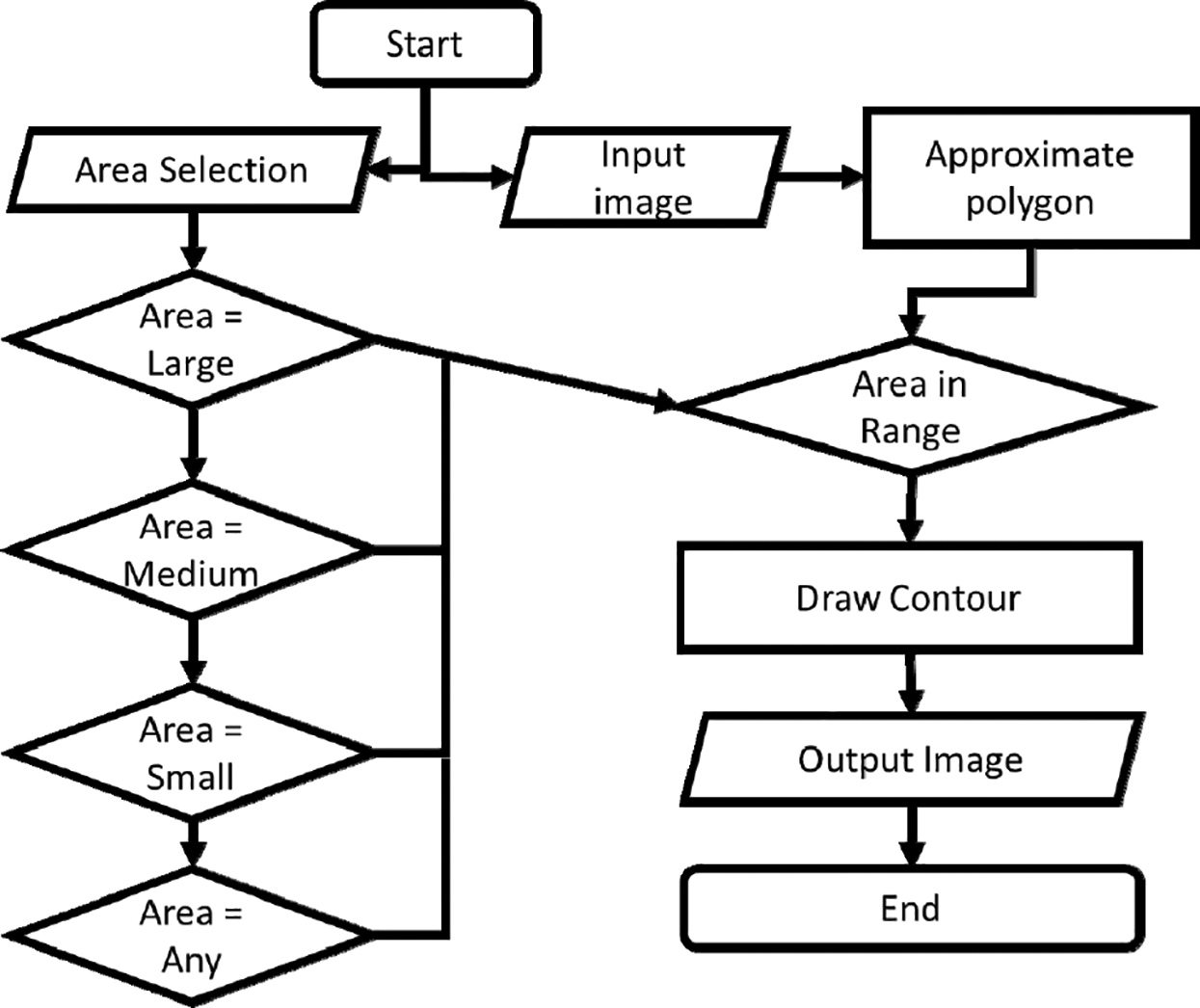
Figure 4: Flowchart demonstrating size sorting algorithm where area taken up by approximated polygon is used in order to identify targeted objects
The algorithms outlined in this subsection act as the backend of this system and are abstracted away by the forward-facing interface with which the system user interacts. The interface design allows users to take full advantage of the complex sorting accomplished by the combination of the three sorting algorithms without them requiring any knowledge of the system’s inner workings. The interface is the part of the system that greatly improves interfacing between the human operator and the machine.
The main advantage of our design compared to previous attempts is user-friendly operation and flexibility. To create a simple, usable interface, we used the Tkinter library, which is the default graphical user interface design library for the Python language. The interface implemented must give the operator visual feedback of the system operation, a high degree of control over the operation of the system, and abstracting away the system’s complexity. All of these goals can be accomplished by using the Tkinter library.
The interface design outlined in this section is implemented as an output for the system and is elaborated upon in Section 3. In the next subsection, we outline the system’s hardware design, which includes the robotic arm and the electronics used for the system as well as the camera and mount used to capture the images of the workspace used to detect, identify and sort objects.
The hardware system implementation is given in the block diagram of Fig. 5. The physical system consists of the webcam, computer, and robotic arm. All three devices are connected to one another over USB. The microcontroller is connected to the servo motors using jumper wires, and the motors are powered using a 5volt supply. The system’s components are shown and described in Tab. 1, and the circuit design of the system is shown in Fig. 6. The physical system constructed for the system consists of the circuit diagram, as shown in Fig. 6. The circuit consists of an Arduino Uno microcontroller and four servo motors. The controller and the servos are powered using a 5 V power supply. The microcontroller is connected using a Universal Serial Bus (USB) to the computer that sends commands to the device to actuate the motors accordingly. The process through which the arm actuates is described in further detail later on. The circuit was modeled in Proteus. Tab. 1 shows the descriptions of the components. As shown in Fig. 6, the circuit is used to implement the serial manipulator, as shown in Fig. 7. The system includes three servos that move and position the gripper, which is actuated by a fourth servo motor. The circuit components are connected via acrylic parts using nuts and bolts. The robotic arm has four degrees of freedom: the rotation about x-axis, y-axis, and z-axis plus opening and closing of the gripper/ The measurements for the mechanical parts of the manipulator are shown in Fig. 8.
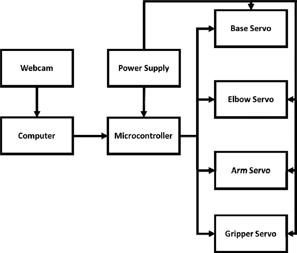
Figure 5: Physical system block diagram showing all connections between the physical components
To successfully position the robotic arm, the message sent from the application must be parsed to extract joint coordinates for each of the servo motors that control the arm. Then, the servo motors rotate according to the flowchart shown in Fig. 9.
Table 1: Description of components
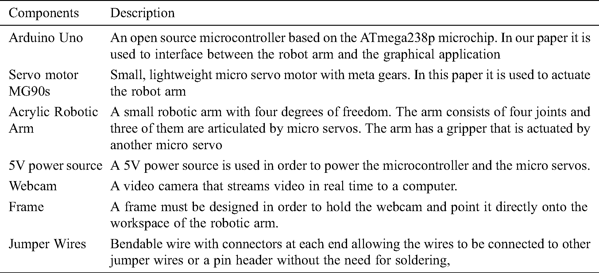
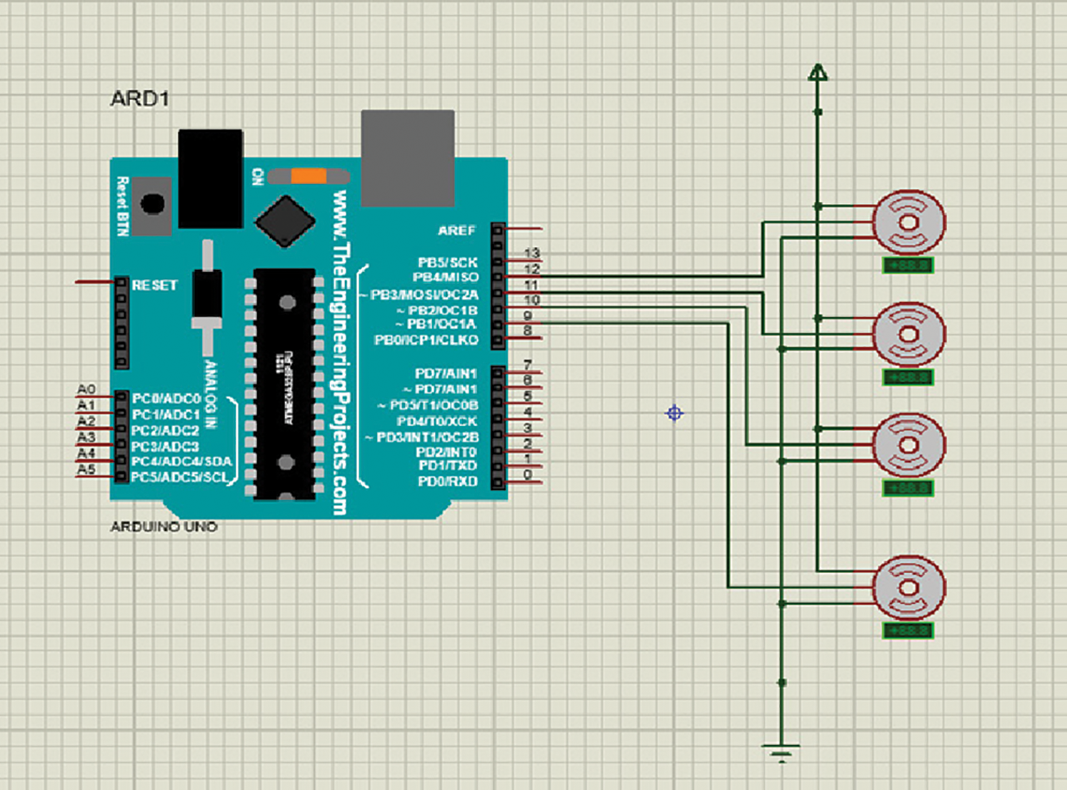
Figure 6: Circuit diagram for the prototype. The system displays the Arduino microcontroller, which controls the servo motors that actuate the joints of the robotic arm
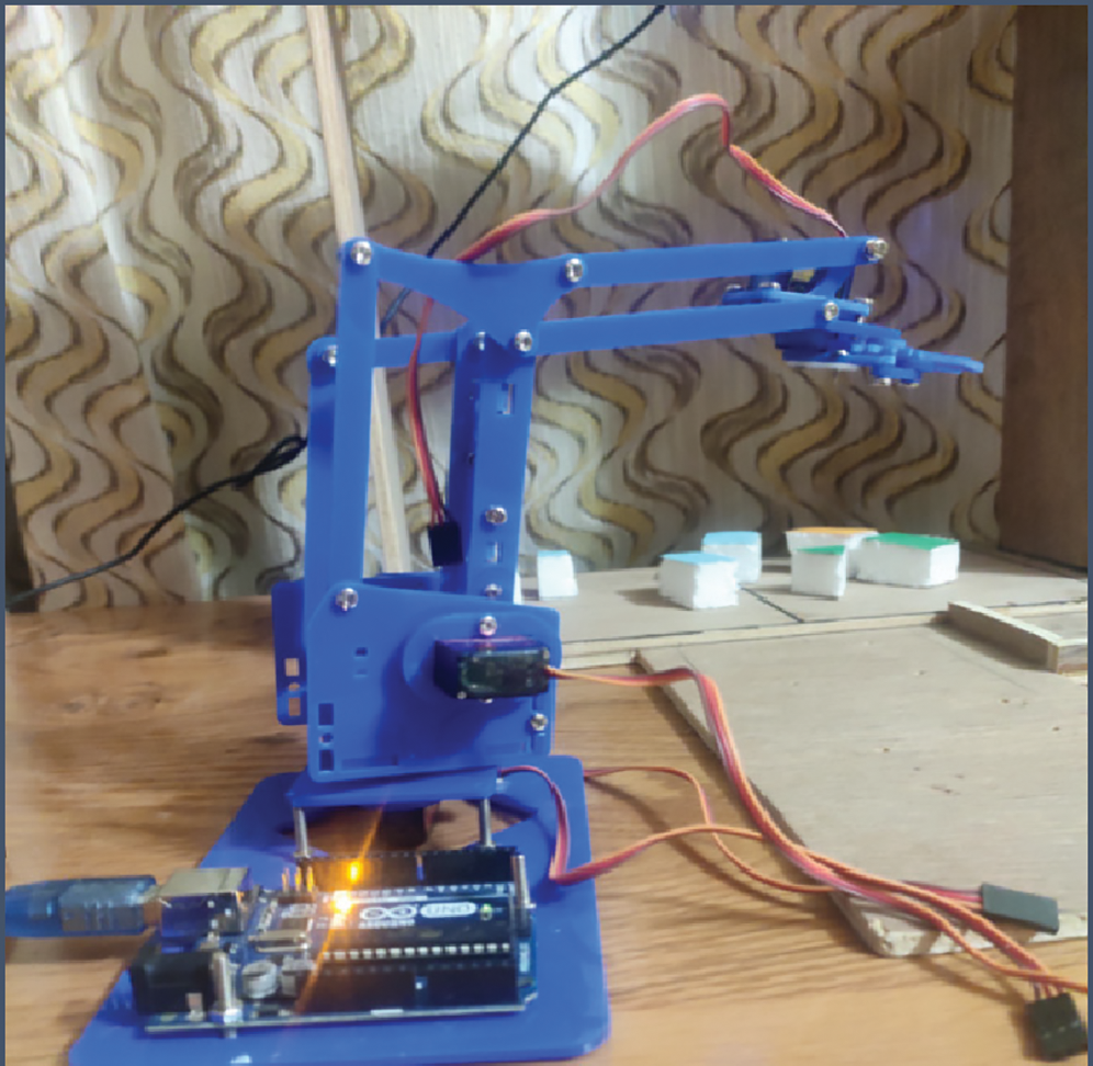
Figure 7: Prototype of robotic arm system
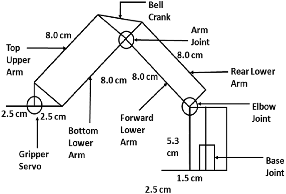
Figure 8: Simplified diagram of the robotic arm, which shoes the length of the robotic arm links and the position of the joints which actuate the robotic system
As shown in Fig. 8, the target position for the respective servo is received from the application. If this value is less than the current servo position, the position is incremented until both values are equal. The same process is followed when the new position is greater than the current position, and the angular position is instead incremented. After the robotic arm grabs the object, the robot arm moves to the preset mid position and then the drop position before returning to the mid position, which is treated as the rest point for the system.

Figure 9: Circuit Diagram for the prototype. The system displays the Arduino microcontroller, which controls the servo motors that actuate the joints of the robotic arm
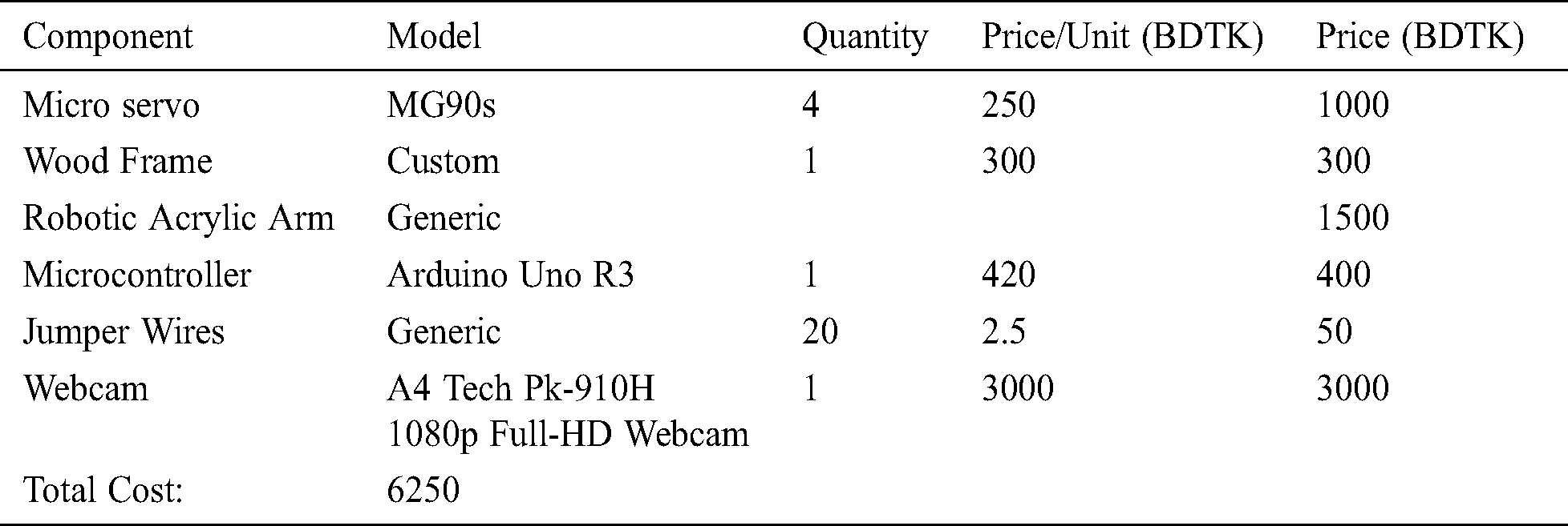
The system is designed and manufactured for a low and affordable price, as is demonstrated in Tab. 2. The system’s overall cost comes down to Taka (Tk.) 6250, which is less than 80 dollars making the implementation of the system inexpensive primarily because the innovation in the design of the system is at the software level and not hardware. Tab. 2 lists the breakdown of the cost of the components required to develop the system. The system was built affordably coming out to Tk. 6250, which when converted, comes out to less than 80 USD(United States Dollar).
Table 2: Cost of the components
The system employs kinematic algorithms in order to automatically position the robotic arm for pick and place activity. The mathematical modeling required to do so is given in the next subsection.
In order for the system to function, the position of selected objects placed in the workspace of the robotic arm, the position of the system must be translated to angular positions for the robotic arm. Firstly, the center of the targeted object is ascertained using the following formulation.
Let n be the number of points in the contour. The centroid (Cx, Cy) of the ith point (xi, yi) is calculated as follows:


The coordinates are currently given in pixel coordinates, and these are converted to Cartesian coordinates using the unitary method. Then, inverse kinematic modeling of the system is done to find joint coordinates for the robotic arm, which positions the end effector’s tip at the centroid position of the target object. The kinematic diagram of the system is given in Fig. 10.
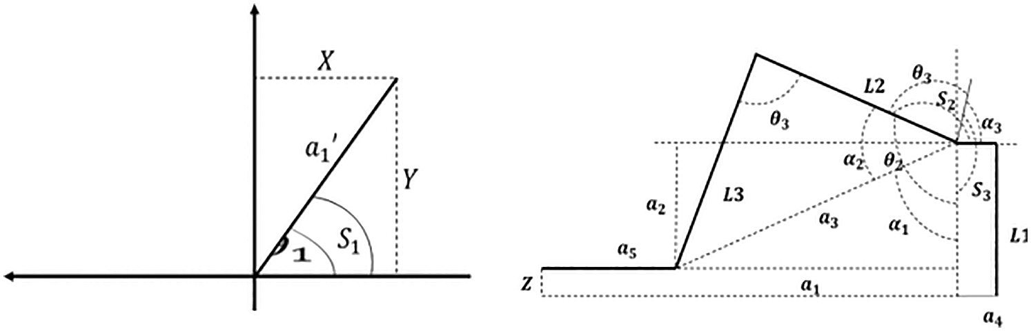
Figure 10: Top view (above) and side view (bottom) of kinematic diagram
The derivation of the equation is given below:


Apply cosine rule in order to find  :
:

Apply cosine rule in order to find  :
:


The joint coordinates of the robotic arm are given by S1, S2, S3 for the base, elbow, and arm servo. The joint coordinates are concatenated and forwarded to the microcontroller controlling the robotic arm to produce the desired motion and perform pick up and place activity.
The next section highlights the output and results obtained via the implementation of the system. This includes the physical system built and the graphical user interface. We also performed testing on the system to find how successful the system is at the job it has been designed to accomplish. This includes testing the system accuracy based on the three sorting algorithms as well as the accuracy of the kinematic modeling and centroid identification. At the end of the next section, we compared the results and design with previous works.
This section discusses the system designed for this project; it shows the results acquired by testing the system; analyze the results to contextualize them. The completed system consists of the robotic arm, the user interface, and the frame, consisting of the camera mount and the workspace for the robotic arm. The full system diagram is shown in Fig. 11.
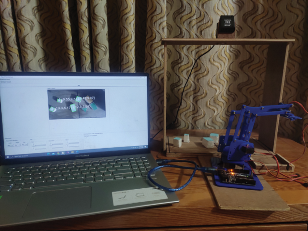
Figure 11: Diagram showing full system consisting of the graphical user interface showing the workspace; wooden frame with a camera mounted; robotic arm with a microcontroller
The graphical user interface implemented for the system is shown in Fig. 12. Going from top to bottom, the user interface consists of the start button, which begins robotic arm action when pressed. Then, there is a label which displays whether a device is connected to the computer. Below that, there is the video feed which displays the objects that the robotic arm targets. At the bottom of the interface, we see the parameter selection tab, which includes three dropdown menus for color, shape, and size. There are the color sliders that are used to manually set HSV value for the object to be sorted to the right of that. Finally, we see the information tab that displays the current activity of the robotic arm. To increase ease of use of the system, the graphical interface displays a green contour on the selected object in accordance with selection parameters. Simultaneously, a white dot is also displayed on the center of the targeted object.
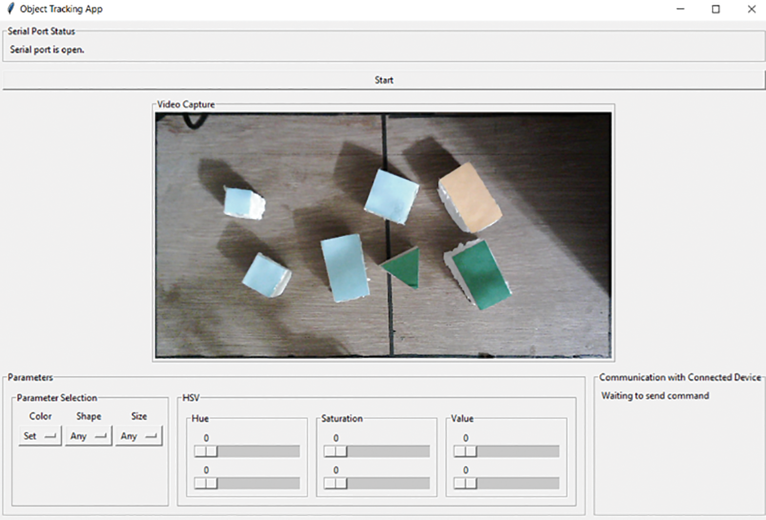
Figure 12: Graphical User Interface when a color has been set to “set”, shape set to any, and size also set to any. Target HSV range is zero, so no objects are highlighted
Table 3: Color selection accuracy
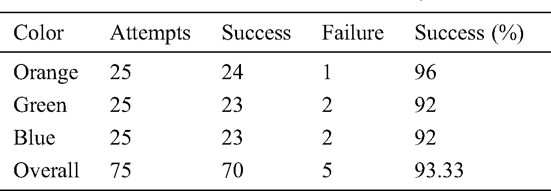
In order to gauge the success of the system, numerous parts of the project must be tested. The section of the system that must be tested includes the accuracy and ability of the system to locate objects based on the three sorting parameters: color, shape, size, the accuracy of the inverse kinematic algorithm. The torque, speed, power consumption of the system are not key parameters for the system as we are primarily concerned with sorting and usability. The sorting parameter tests for the system are designed the same way for each parameter. Three objects that fall into three separate categories for a singular parameter are placed onto the workspace for the robotic arm. A category is selected, and if the contour and centroid are displayed on the correct object, that test is considered a success. This process is repeated for each category in each parameter 25 times. Tabs. 3, 4, and 5 displays the results of our experimentation. Fig. 13 shows sample output when color sorting is done, and a blue object is selected. Fig. 14 shows the sample output of shape sorting in which we are selecting for the square object. Fig. 15 shows the sample output of size sorting where we are selecting for a medium-sized square object. The coordinates for the objects were determined by drawing an axis onto the workspace for the robotic arm as captured by the camera. the x domain ranged from –14 to +14, and the y axis ranged from 0 to 14.

Figure 13: Sample output when color sorting is done, and blue object is selected
Table 4: Shape selection accuracy
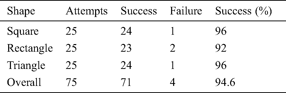

Figure 14: Sample output when color sorting is done and blue object is selected. Shape is set square and size is set to large, So, large blue square is targeted
Table 5: Size selection accuracy
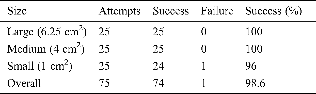

Figure 15: Sample output of size sorting where we are selecting for a large sized square object. Color has been set to blue and shape is set to square. So, selected object is a large blue square
For color sorting, we have a total of 75 attempts, of which 70 are successful, and 5 are considered failures. This gives us an average rate of success of 93.33%. Orange was shown to be the most successful of the three having only a singular failure, while the other two colors have given us two failures each. There were found to be no factors that determine the success of one color compared to another. Therefore, we found the reasoning behind the failures, which was found to be a change in environmental illumination. The failed attempts occurred when there were shadows projected onto the workspace of the robotic arm or lighting conditions changed due to flickering of the environmental light source. Fig. 13 shows a sample output of color sorting, which shows all four blue objects highlighted via the green contour outline and the position of the centroid on each object. As can be seen from Fig. 13, the contour outline traces well around the objects. The edges do not perfectly align because of uneven lighting due to the positioning of the light source as well as fraying at the edges of the target object. The imperfect trace can also be attributed to the approximation multiple used. The success rate for shape sorting came out to be 94.6%. We found 1 failure for both square and triangular objects, while we got 2 failures for rectangular objects. The causes of failure are, in general, the same as for color sorting. Other causes of failure may be the lack of discernibility between the shapes. The algorithm on one of the failures for the rectangle mistook it for a square, and on the failure for the triangle, it was mistaken also mistaken for a square. Size sorting had the highest degree of success, only giving us a singular failed attempt, and this failure can also be attributed to uneven lighting conditions.
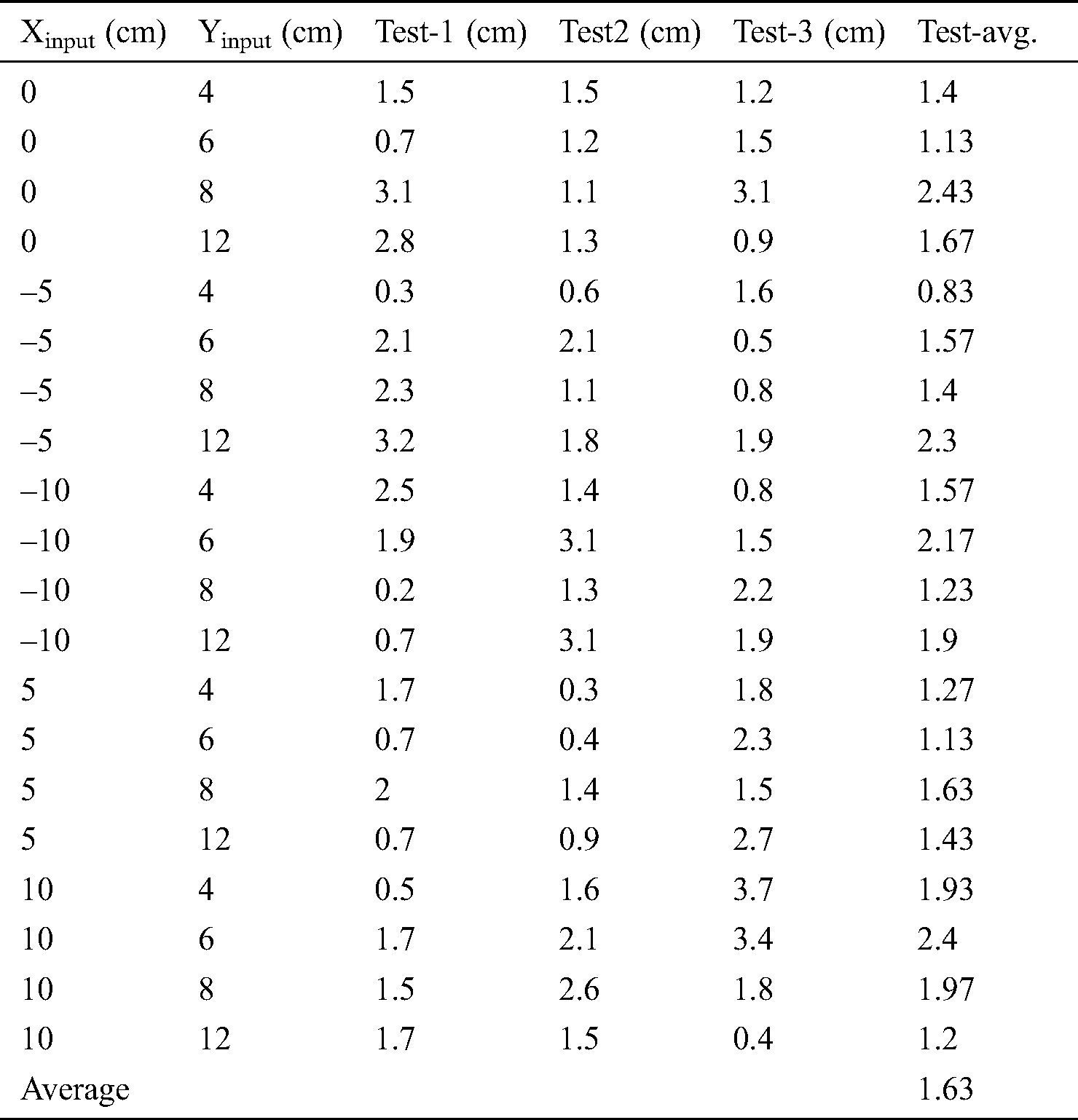
Tab. 6 shows the results of the arm positioning test. The inverse kinematics of the system was tested to ensure that the robotic arm is placed accurately enough to pick up target objects. The test was designed in the following manner: twenty evenly spaced points were selected on the workspace. The coordinates of each of those points given as input to the inverse kinematic algorithm. An error was calculated by measuring displacement between the terminal of the end effector and the target centroid location. The test was repeated three times for each point and then averaged to get a mean error for each position. Then, after the test was carried out for all points, we derived mean error for the system.
The arm position test produced an average error of 1.63 cm, meaning that on average, the tip servo gripper to the position marked on the workspace was 1.63 cm. The maximum error produced was 3.4 cm. The error in the system can be attributed to multiple causes. Firstly, an error can be caused due to the accuracy of the servo motors used for the system because the accuracy of commercially available servo motors can vary by up to 5 degrees. Efforts were made to reduce the impact of such inaccuracy by calibrating the servos beforehand. Another cause of inaccuracy is the mechanical design of the robotic arm. The robotic arm links often rubbed up against each other, creating friction that reduced the accuracy of the system. The accuracy of the arm remained relatively constant throughout the assigned workspace for the system. The highest error for the system occurred at (0,8) and (10,6). However, this inaccuracy can be attributed to the previously stated sources of error. Otherwise, the accuracy of the arm remains consistent throughout the workspace, and there is no relationship that can be derived between arm accuracy and object positioning.
Table 6: Results of arm positioning test
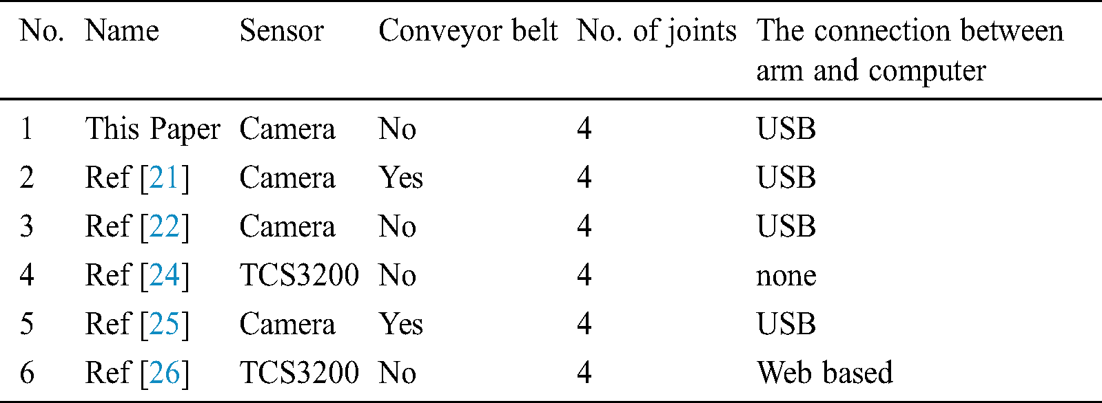
Overall, through the testing of the features elaborated in this section of the paper, the system can be assessed as a success. Tab. 7 shows the hardware comparison between our system and other systems that attempt to accomplish the same task. Tab. 8 shows the software comparison between our system and other systems of the same category.
This paper, similar to [21,22,25,27,29] uses a camera as the primary input for the system. The other systems use TCS3200 color sensors as input devices. A camera is a comparatively better option for input for such a system because it allows for the application of more filtering parameters apart from just color without the addition of more sensors. In Thike et al. [27], the author uses both sensors. However, a camera is used to target objects for picking up, and TCS3200 is used to identify drop points. The solution designed in Thike et al. [27] allows for multiple drop points that can be switched around. This utility can easily be replicated in software through the utilization of our kinematic algorithm. Systems in Abbood et al. [21,25,28] also add conveyor belts to their system. [21,25] use conveyor belt systems merely to be more representative of a factory environment, but this is unnecessary for our system as the kinematic algorithm allows the robotic arm to pick up objects placed at any position within the workspace of the robotic arm. All of the systems that we compared with our system use robotic arms with four degrees of freedom. This is because the systems are designed to pick and place objects; manipulating the object after being picked up is unnecessary, so four degrees allows to move the system along three dimensions and gripping and releasing the objects. All of the systems except [24,28] connect to a computer, either a Raspberry Pi or a desktop. The two unconnected systems only connect to microcontrollers, so all processing is completed in the embedded system. This approach reduces cost and reduces the usage of the system by not allowing for the use of computer vision-based sorting due to lack of processing power.
Table 7: Hardware comparison with other articles
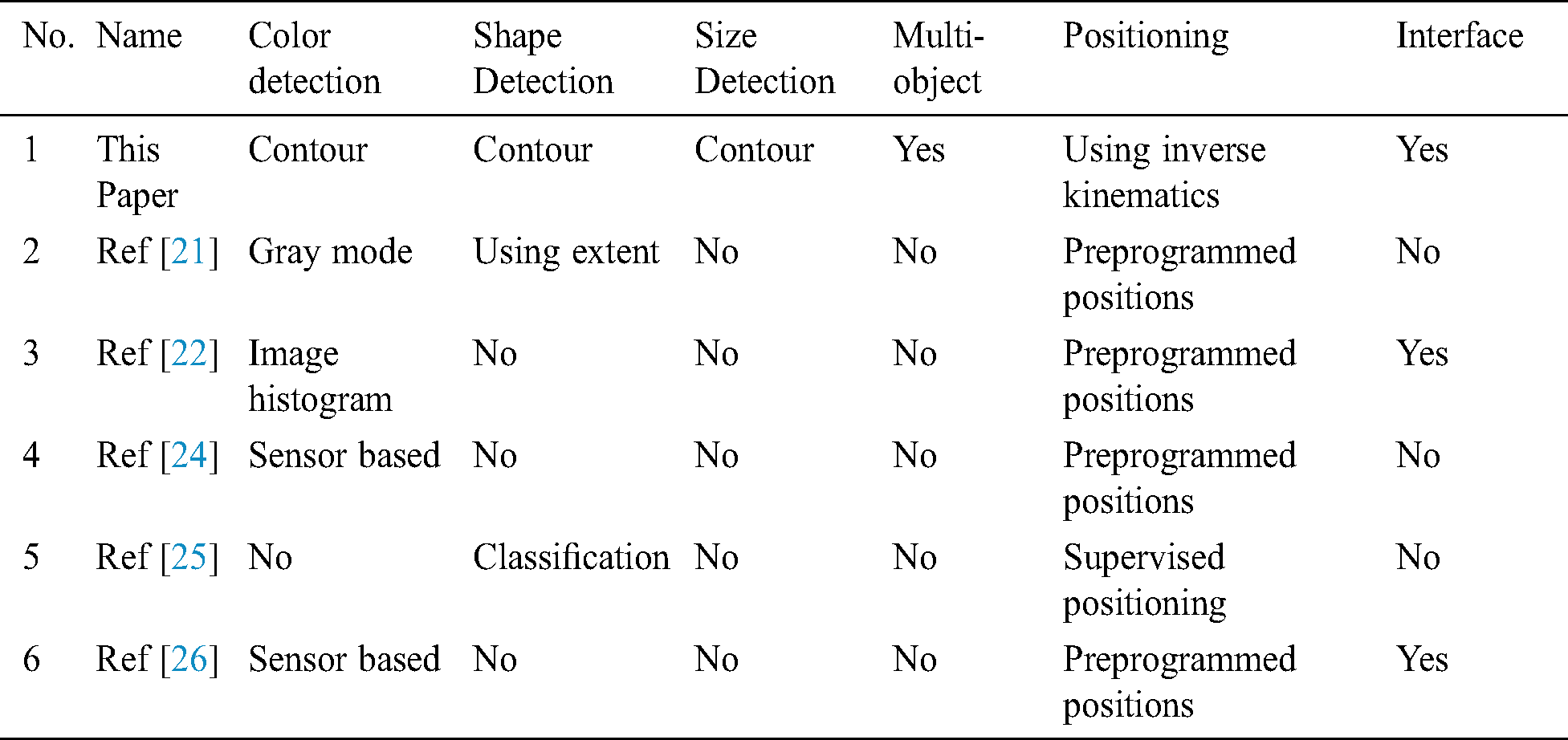
This proposed system of this paper implements three sorting algorithms compared to the other systems which only implement one or two sorting algorithms. All of the systems which we performed comparison against, implement color-based sorting, while [21,25] implement shape sorting as well. In Abbood et al. [21], similar to our system shape sorting is used to identify simple shaped objects, and in Liu et al. [25], a more complex classification system is used to identify and group objects of similar shape. [29] implements size sorting by calculating the diameter of the fruits based on contour moments. Our filtering requires much less computation than the other systems used because contouring is applied to an object based on HSV mode analysis and then calculations are performed based on that single action. Our system is also the only system that is capable of performing pick and place on multiple targets through the use of our kinematic algorithm as opposed to the other systems which use pre programmed positions. Furthermore, the use of our kinematic algorithm to control the robotic arm allows the robotic arm to pick up target objects at any position on the workspace. Finally, our graphical user interface allows for user control of the system without having any knowledge on the inner workings of the system. [22,26] also have graphical interfaces, but [22] only allows for system monitoring, and [26] only allows for color selection and no monitoring. Our system allows for selection based on any of our three parameters as well as monitoring. Plus, by highlighting the targeted object in the video capture, users also have more valuable information. The comparative analysis between our system and the reference systems shows that our system has significantly improved upon previous work in the category. The results obtained through testing of the system show that our system has acceptable levels of accuracy for all selected parameters, and the kinematic algorithm positions the arm accurately enough to successfully grab target objects.
This paper presents a design and implementation of a robotic vision system operated using an interactive Graphical User Interface (GUI) application. The application allows users to determine their desired object, which is then picked up and placed by a robotic arm into the target location. The three parameters used for object selection are three of the primary features based on which sorting is done in the industry. For example, the system may be used on a dock to sort freights or in an airport for luggage picking. Further applications include usage in the food industry for sorting of grains, fruit, and vegetables. In essence, the system may be used in any location where sorting and pick and place operation is required. There are some assumptions considered to construct this system: (i) the impact of the mass of the target object on the robotic arm is ignored, (ii) an object will be placed on an even plane with no negative or positive elevation for the object, (iii) all angles to be right angles for rectangular and square objects. The device also has a few limitations: (i) the robotic arm goes through the required motions even if the object picked up is dropped, and (ii) there is no feedback mechanism for the system apart from being watched over and reported by the user. In the future, the system can be improved and modified in several ways. The microcontroller used to control the system can be changed to a Raspberry Pi, allowing all joints of the robotic arm to be manipulated simultaneously. A line of motion camera can be added to the system instead of a webcam, which would allow the workspace to be three dimensional to two dimensional.
Acknowledgement: Authors would like to thank the Department of Electrical and Computer Engineering of North South University and Taif University Researchers Supporting Project number (TURSP-2020/10), Taif University, Taif, Saudi Arabia.
Funding Statement: Taif University Researchers Supporting Project number (TURSP-2020/10), Taif University, Taif, Saudi Arabia.
Conflicts of Interest: “The authors declare that they have no conflicts of interest to report regarding the present study.”
1. W. G. Hao, Y. Y. Leck and L. C. Hun. (2011). “6-DOF PC-based robotic arm (PC-ROBOARM) with efficient trajectory planning and speed control,” in Proc. 4th Int. Conf. on Mechatronics (ICOMKuala Lumpur, Malaysia, pp. 1–7. [Google Scholar]
2. A. A. Mohammed and M. Sunar. (2015). “Kinematics modeling of a 4-DOF robotic arm,” in Proc. Int. Conf. on Control, Automation and Robotics, Singapore, pp. 87–91. [Google Scholar]
3. K. Weman. (2003). Welding Processes Handbook, Cambridge, England: Wood Head Publishing Limited, . [Online]. Available: https://www.globalspec.com/reference/80943/203279/welding-processes-handbook. [Google Scholar]
4. E. Appleton and D. J. Williams. (2020). Industrial Robot Applications, Switzerland AG: Springer Nature, . [Online]. Available: https://link.springer.com/book/10.1007%2F978-94-009-3125-1. [Google Scholar]
5. E. Insight. (2008). “Less is more with new ABB painting robot,” Industrial Robot, vol. 35, no. 2, pp. 1. [Google Scholar]
6. W. I. Muzan, T. Faisal, H. M. A. A. A. Assadi and M. Iwan. (2012). “Implementation of industrial robot for painting applications,” Procedia Engineering, vol. 41, no. 2012, pp. 1329–1335. [Google Scholar]
7. R. A. Beasley. (2012). “Medical robots: Current systems and research directions,” Journal of Robotics, vol. 2012, no. 2, pp. 1–14. [Google Scholar]
8. H. Takanobu. (2008). Dental Patient Robot, Princes Gate Court. London, United Kingdom: IntechOpen Limited, . [Online]. Available: http://www.intechopen.com/books/medical_robotics/dental_patient_robot. [Google Scholar]
9. J. Hollingum. (2000). “Precision drilling robot,” Industrial Robot, vol. 27, no. 4, pp. 1. [Google Scholar]
10. Y. Yao. (2014). “Design and experiment of a robot automatic drilling system,” SAE Aerospace Manufacturing and Fastening Conf. and Exhibition, Salt Lake City, USA, pp. 1–3. [Google Scholar]
11. A. Gatej, N. Pyschny, P. Loosen and C. Brecher. (2012). “Robot-based resistance soldering of optical components,” Soldering and Surface Mount Technology, vol. 24, no. 2, pp. 112–119. [Google Scholar]
12. H. Yamagata. (2005). “Intelligent welding and soldering with cold metal transfer,” Industrial Robot, vol. 32, no. 5, pp. 1–2. [Google Scholar]
13. K. Lee, J. Lee, B. Woo, J. Lee, Y. Lee et al. (2018). , “Modeling and control of a articulated robot arm with embedded joint actuators,” in Proc. Int. Conf. on Information and Communication Technology Robotics (ICT-ROBOTBusan, South Korea, pp. 1–4. [Google Scholar]
14. J. Martinez, J. Bowles and P. Mills. (1996). “A fuzzy logic positioning system for an articulated robot arm,” in Proc. IEEE 5th International Fuzzy Systems, New Orleans, LA, USA: Hyatt Regency Hotel, pp. 251–257. [Google Scholar]
15. P. S. Sanchez and F. R. Cortes. (2010). Cartesian Control for Robot Manipulators, Princes Gate Court, London, United Kingdom: IntechOpen Limited, . [Online]. Available: http://www.intechopen.com/books/robot-manipulators-trends-anddevelopment/cartesian-control-for-robot-manipulators. [Google Scholar]
16. C. Torres, J. D. J. Rubio, C. F. A. Ibáñez and J. H. P. Cruz. (2014). “Stable optimal control applied to a cylindrical robotic arm,” Neural Computing and Applications, vol. 24, no. 3–4, pp. 937–944. [Google Scholar]
17. N. Smith. (2004). “Smaller, faster SCARA,” Industrial Robot, vol. 31, no. 4, pp. 1–2. [Google Scholar]
18. B. C. Fenner. (2005). “New delta robot picks up the pace,” Industrial Robot, vol. 32, no. 1, pp. 1–2. [Google Scholar]
19. J. Shufelt. (2000). Geometric Constraints for Object Detection and Delineation, Boston, MA, USA: Springer, . [Online]. Available: https://link.springer.com/book/10.1007/978-1-4615-5273-4#toc. [Google Scholar]
20. A. Khashman. (2010). Intelligent Global Face Recognition, Princes Gate Court, London, United Kingdom: IntechOpen Limited, . [Online]. Available: http://www.intechopen.com/books/face_recognition/intelligent_global_face_recognition. [Google Scholar]
21. W. T. Abbood, O. I. Abdullah and E. A. Khalid. (2020). “A real-time automated sorting of robotic vision system based on the interactive design approach,” International Journal on Interactive Design and Manufacturing (IJIDeM), vol. 14, no. 1, pp. 201–209. [Google Scholar]
22. Y. Divya and C. P. Kumar. (2020). “Machine vision based color recognition by robotic arm using Lab VIEW,” CVR Journal of Science & Technology, vol. 18, no. 1, pp. 100–104. [Google Scholar]
23. T. Dewi, S. Nurmaini, P. Risma, Y. Oktarina and M. Roriz. (2020). “Inverse kinematic analysis of 4 DOF pick and place arm robot manipulator using fuzzy logic controller,” International Journal of Electrical and Computer Engineering (IJECE), vol. 10, no. 2, pp. 1376–1386. [Google Scholar]
24. A. Najmurrokhman, K. Kusnandar, F. Maulana, B. Wibowo and E. Nurlina. (2019). “Design of a prototype of manipulator arm for implementing pick-and-place task in industrial robot system using TCS3200 color sensor and ATmega2560 microcontroller,” Journal of Physics: Conf. Series, Malang, Indonesia: Annual Conf. of Science and Technology, vol. 1375, pp. 1–7. [Google Scholar]
25. X. Liu and S. Jin. (2020). “Multi-target visual recognition and positioning methods for sorting robots,” IOP Conf. Series: Materials Science and Engineering, vol. 892, The Third International Workshop on Materials Science and Mechanical Engineering (IWMSME 2020), Hangzhou, China, pp. 1–7. [Google Scholar]
26. G. I. E. Panie and A. B. Mutiara. (2018). “Development of robotic arm for color based goods sorter in factory using TCS3200 sensor with a web-based monitoring system,” in Proc. Third Int. Conf. on Informatics and Computing (ICICPalembang, Indonesia, pp. 1–6. [Google Scholar]
27. A. Thike, Z. Z. M. San and Z. M. Oo. (2019). “Design and development of an automatic color sorting machine on belt conveyor,” International Journal of Science and Engineering Applications, vol. 8, no. 7, pp. 176–179. [Google Scholar]
28. R. A. Magadum and U. L. Bombale. (2019). “Intelligent color based object sorting using robotics,” International Journal of Robotics, vol. 9, no. 1, pp. 43–48. [Google Scholar]
29. T. Dewi, P. Risma and Y. Oktarina. (2020). “Fruit sorting robot based on color and size for an agricultural product packaging system,” Bulletin of Electrical Engineering and Informatics, vol. 9, no. 4, pp. 1438–1445. [Google Scholar]
 | This work is licensed under a Creative Commons Attribution 4.0 International License, which permits unrestricted use, distribution, and reproduction in any medium, provided the original work is properly cited. |