DOI:10.32604/iasc.2021.015071
| Intelligent Automation & Soft Computing DOI:10.32604/iasc.2021.015071 | |
| Article |
Ontology-Based Verification of UML Class Model XOR Constraint and Dependency Relationship Constraints
1Department of Information Systems, Najran University, Najran, 61441, Saudi Arabia
2Department of Computer Science, SMI University, Karachi, 76400, Pakistan
3Department of Software Engineering, University of Gujrat, Gujrat, 50700, Pakistan
4Department of Software Engineering, National University of Modern Languages (NUML), Islamabad, 44020, Pakistan
*Corresponding Author: Asadullah Shaikh. Email: asshaikh@nu.edu.sa
Received: 05 November 2020; Accepted: 22 December 2020
Abstract: Unified Modeling Language (UML) models are considered important artifacts of model-driven engineering (MDE). This can automatically transform models to other paradigms and programming languages. If a model has bugs, then MDE can transfer these to a new code. The class model is a key component of UML that is used in analysis and design. Without a formal foundation, UML can create only graphical diagrams, making it impossible to verify properties such as satisfiability, consistency and consequences. Different techniques have been used to verify UML class models, but these do not support some important components. This paper transforms and verifies unsupported components such as XOR association constraints and dependency relationships of a UML class model through ontology. We use various UML class models to validate the proposed ontology-based method, easy and efficient transformation and verification of unsupported elements. The results show this approach can verify large and complex models.
Keywords: Ontology-based verification; model verification; class model verification; UML model verification
In today’s world, there is an extensive use of software in high-end television sets, mobile phones, cars and other devices. With it being used so commonly, software failure understandably may lead to human and economic losses. For example, in 2017 [1], a software bug caused the Cloudflare network to leak sensitive customer data such as passwords and cookies. Again, due to software errors, some 3200 prison inmates were released early in the United States between 2003 and 2015 [2]. In 1991, a missile-defense system in Saudi Arabia failed to identify an attack due to inaccurate tracking software, at a cost of 28 lives. The above examples illustrate the importance of software development and verification [3]. In the development phase, it is important to check for the absence of errors. This can be done in later stages after coding of development. Error correction is much more expensive in the later than in the earlier stages of development [4].
The software industry seeks high-level quality assurance at a low cost in a short time. For competitive reasons, software should be of moderate quality when delivered. Developers rely on the end-user to discover bugs. However, a modest level of quality is essential. Software quality can be significantly improved by using model verification [5], in which Unified Modeling Language (UML) models are created at an early phase. Proper verification of UML models may serve to solve several problems that might occur in later stages of software development [6]. A UML model can verify software for correctness and violations of constraints. Models are considered the most important elements in software development, especially in model-driven engineering (MDE) [7,8].
The automatic transformation provides systematic reuse of existing artifacts. However, this can cause problems, such as models with errors that are implicitly passed on to the code. Hence model verification is necessary [9,10]. This ensures that a model is bug free, correct and consistent. Consistency is the most fundamental element of property correctness [11]. It verifies that model elements are consistent with the declaration. In UML class model verification, a model is considered consistent when it has a valid non-empty instance [12].
UML offers various models to address different aspects of software [4,13]. The class model is the most important. It uses simple diagrammatic notation to specify static aspects of a system [14]. The main elements of a class diagram are their classes and relationships, i.e., dependency, association and generalization [15–17]. These are the relational building blocks of UML and the most important elements of object-oriented modeling [18].
Current UML class model verification methods are sufficient to check for correctness. However, they do not focus on some fundamental elements of the class model. A comparison of class model verification methods [19] indicate that dependency relationships are not supported. The XOR constraint is another graphical element that is not supported by any verification method. In some Object Constraint Language (OCL)-supported verification methods, XOR constraints can be presented through OCL constraints and indirectly verified, but OCL has some limitations. For example, the UML specification does not restrict constraint language, and accordingly, constraints can be defined through formal languages, informal languages (JAVA, C#) and natural languages [20,21]. Most computer-aided software engineering (CASE) tools do not support OCL, nor do they provide limited support because commercial CASE providers do not see a large OCL market [22,23]. Indeed, the use of OCL in software development is of little significance [22,24]. It may be hard to understand because several equivalent implementations are possible for a constraint [25]. Hence, designers may have difficulties when it is combined with a diagrammatic paradigm, and even heavy users of UML barely employ OCL [22,24–27]. Moreover, current UML/OCL model verification methods do not deal with the consequences and do not formalize through OCL, which is essential in verification because it may cause a model to become inconsistent.
Ontology is a metaphysical discipline practiced by researchers since the 16th century for real-world representation and categorization. Computational ontology provides a formal model of a system which is currently used as a computational artifact for computer-based decisions on domain knowledge [28]. There are five types of components. (1) Concepts represent values that may be abstract or concrete, such as a task description, function, reasoning process, or action. They are like the classes of a UML class model. (2) Taxonomies organize concepts into generalization and specialization relationships. An example is the generalization relationship of a UML class model. (3) Relations specify interactions among objects of classes. They are like the binary associations of a UML class model. (4) Axioms are model sentences that are always true. They are specified in ontology for specific constraints. (5) Individuals represent concrete or abstract objects such as people, machines, articles, jobs, or functions. They are like objects of a UML class model.
Several tools are used to develop ontologies. The widely accepted Protégé is a free, open-sourced tool developed by Stanford University primarily for biomedical projects. Protégé is currently being used to support formats such as RDF/XML, Turtle, OWL/XML and OBO including reasoners like pellet, racer, fact++ and HermiT.
Verification methods use many formal and semi-formal methods to validate UML class models. They are hard to understand, use much mathematical notation and are different from UML class models. Ontology and UML class models have related features such as classes, generalization and relationships. Ontology has a powerful reasoner that can be quickly and easily applied on complex problem spaces and draw inferences from thousands of ontological items [29]. Consequently, the reliability and consistency of MDE can be improved using an ontology-based verification method.
This work focuses on the design and development of a rigorous method based on an ontology that facilitates transformation and verification of UML class model elements. The results show that the proposed method can significantly reduce verification time. For evaluation, we transform a UML class model to Protégé ontology.
To develop the model, the top-level elements of ontology are first developed, e.g., UML classes are transformed to ontology concepts and association relationships into object properties. Following this, classes and object properties are associated through domain and range. Proposed constraints are implemented in Protégé and the model’s consistency is checked through the pellet reasoner in Protégé.
The rest of this paper is structured as follows. Section 2 presents related work. Section 3 focuses on an example and Section 4 explores the transformation and verification of XOR constraints. Section 5 presents the transformation and verification of dependency relationships. Section 6 describes the experimental results, which illustrate the proposed approach efficiently and effectively verifying UML model elements. Section 7 provides conclusions and future directions.
Many researchers have worked on UML model verifications and discussed correctness properties such as consistency, satisfiability and constraint redundancy according to various aspects, such as the intra/inter-model and static/dynamic models [30]. The verification of the static model concerns only with structural parts such as attributes, associations, aggregation/composition and generalization, while that of the dynamic model considers behavioral elements such as operations. Consistency between models is checked by inter-model verification and consistency of a model against its graphical and textual constraints is subject to intra-model verification. In initial research work, many researchers use the B method, Z notation and description logic (DL) for transformation rules and the meta-model [31–33]. However, current research focuses more on consistency and satisfiability [30,31,34–36,19].
France et al. have presented a formal representation of a core meta-model in Z notation [32]. They have shown that this offers benefits such as consistency checking, clarity, refinement and proof chaining. This also specifies the core meta-model by a compositional schema that contains sub-schemas. Object-Z, which is an object-oriented flavor of Z notation, has been used to define the abstract syntax of a UML meta-model [37,38]. Furthermore, the authors argue that the formal specification of the UML meta-model is the most common method to describe language semantics. They propose an integrated framework whose formalism varies according to the verification task. The B formal method has been used to formalize UML models [33,39]. This work verifies UML class model consistency against the well-formedness rules by B prover [39]. They present OCL constraint transformation [33] and transform OCL basic data types to B method basic types and OCL operators to those of the B method.
Researchers have used semi-formal methods such as constraint satisfaction programming (CSP) and Alloy to verify UML class models. A method of UML class model verification was proposed by Cadoli et al. [13], using CSP to represent and solve linear inequalities that worked on satisfiability and full satisfiability. In satisfiability, they verify whether a finite non-empty instance of a class model can be constructed without violating any constraints. In full satisfiability, they ascertain whether an instance model can be constructed in which all classes can be populated without violating constraints. A constraint logic programming-based framework has been presented in a previous study [40], which translates and provides reasoning on UML models through CSP. In the proposed framework, reasoning on the model is done through the model–finding formula and the framework supports the satisfiability checking of OCL fragments. In this connection, the authors have also developed an Eclipse plug-in for the proposed framework.
Cabot et al. [41] proposed a set of techniques to facilitate the efficient integrity checking of UML-based software specifications. They worked on events only responsible for constraint violations, which they called potential structure events (PSEs). PSEs were recorded for each constraint and only those entities and relationships relating to PSEs were verified. A method based on linear inequalities was used to verify generalization relationships, qualified associations and association classes [36,42,43]. This work presented a redundancy elimination method for universal and existential quantifier constraints for aggregation/composition, association, generalization and qualified association. The authors proposed incremental verification methods for internal consistency of UML/OCL class models. These methods decrease cost of re-verification of the class model. For example, if a new OCL invariant was added to the model, then only that invariant was checked [44].
The semi-formal method Alloy has been used to verify UML class models. Bordbar et al. [35] transformed a UML class model into the signature of an Alloy model as a meta-model instance to facilitate the analysis of the system via Alloy. Maoz et al. [45] formalized the advanced elements of a UML model, such as interfaces and multiple inheritances, to Alloy. They performed different types of reasoning on the class model, such as model intersection and refinement analysis. Berardi et al. [31] used DL to check for redundancies and inconsistencies in a UML class model and argued that a DL-based approach can support reasoning on a large and complex UML class model. This work checked satisfiability and class equivalence.
Ontology has been used to verify UML class models. Xu et al. [46] compared UML and Web Ontology Language (OWL), and found similarities such as classes, relationships and attributes. They also found dissimilarities. For example, OWL has only object property to make relationships among classes, while UML has relationships such as association, aggregation and composition. Belghiat et al. [47] proposed an ontology graph-based specification of a UML meta-model. Parreiras et al. [29] integrated OWL and UML to represent a UML model and incorporated the Meta-Object Facility (MOF) model in ontology as the backbone for OWL and UML.
A model slicing technique was used to verify a complex UML model. Shaikh et al. [19] proposed a technique to reduce the complexity of verification by decreasing the verification time of a large model and a feedback technique for an unsatisfiable UML/OCL class model [48].
Current UML class model verification methods are sound, and they efficiently verify the correctness of models. However, they can consume substantial computational resources and may not generate results, especially for large and complex models. Furthermore, they do not support some essential elements of the UML class model.
Throughout this paper, we use an example of an office task distribution system to demonstrate our approach. The model has five classes, four associations marked as XOR and one dependency relationship. In the given example, the Task class is connected with the Outsource and Employee class through the Award association. This specifies that the instance of the Task class can be connected with the instance of the Employee class or, the Outsource class. The Employee class relates to the Committee class through two associations, Member and Chair. These specify that the instance of the Employee class can relate to the instance of the Committee class through either a Member or Chair relationship. The Employee class also has a Uses dependency relationship with the Tool class.
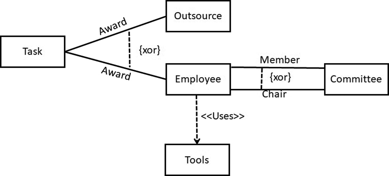
Figure 1: A partial UML class model of office task distribution
4 Transformation and Verification of XOR Constraints
The UML class model has two types of XOR constraints: (1) Two classes are connected through different associations, which are marked as XOR in Fig. 1, where Employee is connected to the Committee class either through Member or Chair; and (2) The XOR constraint is attached to three classes. For example, a class connected to two classes with the same association. The Award association is connected to three classes and specifies that a task can be either outsourced to a company or awarded to an employee. In the proposed solution, the first type of XOR semantic can be achieved in the ontology by making the XOR-annotated associations with two disjoint object properties. For example, the Member and Chair associations among Employee and Committee are declared as disjoint to one another. The second type of XOR semantic can be achieved by declaring the OWL sub-class restriction. For example, the Award association constraint is transformed to the following sub-class constraint:

4.1 Satisfiability of Case 1 XOR Constraint
Consider a fragment of the class model shown in Fig. 1, where an Employee class connects to the Committee class through XOR associations, Member and Chair. According to the proposed approach, Member and Chair are declared disjoint object properties. An instance of the class Employee can be linked to the Committee class either through Member or Chair, as shown in Fig. 2. Otherwise, an Employee class instance makes a connection with an instance of Committee through both object properties and the model is unsatisfied, as shown in Fig. 3. Suppose we have the following instances of classes:

The ontology graph connectivities satisfying the restrictions are as follows:


The ontology graph connectivities that do not satisfy the restrictions are:


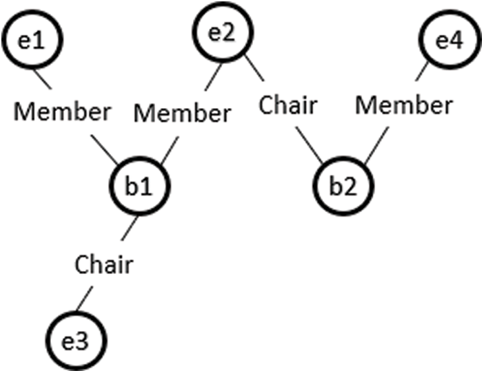
Figure 2: Ontology graph for a valid instance model of case 1 XOR constraint
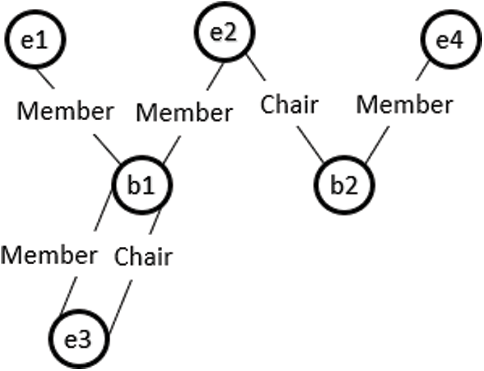
Figure 3: Ontology graph for an invalid instance model of case 1 XOR constraint
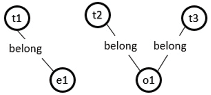
Figure 4: Ontology graph for a valid instance model of case 2 XOR constraint
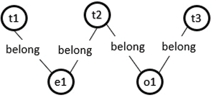
Figure 5: Ontology graph for an invalid instance model of case 2 XOR constraint
4.2 Satisfiability of Case 2 XOR Constraint
Consider the class model in Fig. 1, where a Task class connects to the Employee and Outsource classes through XOR association Award. According to the proposed approach, an instance of the Task class can be connected to either the Employee or Outsource instance through association Award, as shown in Fig. 4. Otherwise, the model will be unsatisfied, as shown in Fig. 5.
Suppose we have the following instances of classes:

The ontology graph connectivities satisfying the restrictions are:

The ontology graph connectivities that do not satisfy the restrictions are

4.3 Satisfiability Verification Example of an Inconsistent XOR Constraint
Consider the inconsistent class diagram shown in Fig. 6, where the Salesman class is connected to Vehicle and Commercial Vehicle class through travel by the XOR association. In the first instance, it is difficult to see that the model is inconsistent because it does not satisfy the correctness property. i.e., “satisfiability,”. An instance of a Salesman connects to an instance of either Vehicle or Commercial Vehicle through travel by association. When this happens, the model is unsatisfied due to the generalization relationship between Vehicle and Commercial Vehicle. The instance of Commercial Vehicle is also considered an instance of Vehicle, which violates the XOR constraints. The model formalized in the ontology using Protégé, and the reasoning outcome, is summarized in Fig. 7, which shows that the ontology is inconsistent.
5 Transformation and Verification of Dependency Relationships
Dependency relationships are semantic relationships between UML classes. They state that a change in a class can affect another class. They are used in different UML diagrams, such as packages components and uses. Here, only dependency relationships related to the class model that can impact its correctness are considered. Hence, the focus on the dependency relationships of create, drive, call and use. Consequently, the relationships to the object property with some restrictions are transformed. For example, the call and use dependencies are declared transitive, while the create and drive dependencies are transitive and asymmetric.
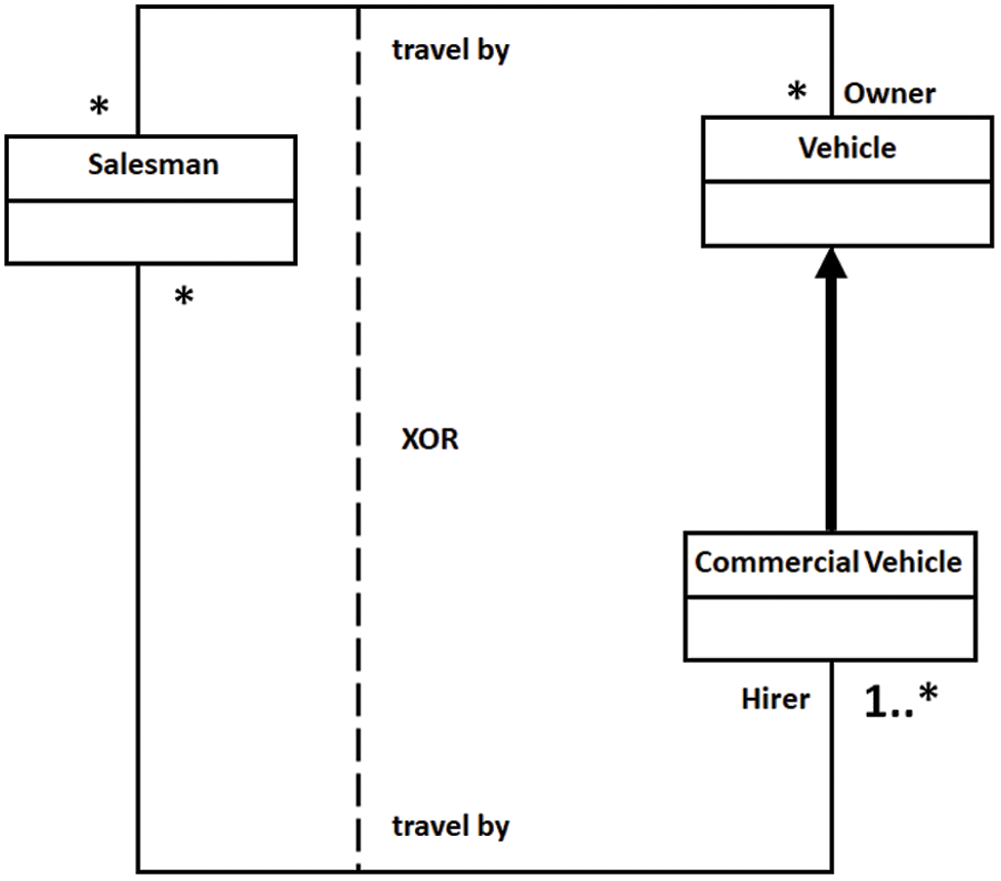
Figure 6: Unsatisfied XOR association constraint
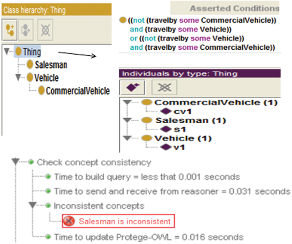
Figure 7: Reasoning outcome obtained in Protégé of unsatisfied XOR association constraint
Sometimes a model can be unsatisfied due to its implicit properties. For example, Fig. 8 shows a UML class model in which an instance of class A creates an instance of class B, an instance of class B creates an instance of class C, and an instance of class D creates an instance of class A. The class C is a subclass of class D.
Fig. 9 shows the ontology graph before the inference of the UML class model. The graph after this inference is presented in Fig. 10. The result of the inference shows that the model is cyclic and will not be finitely satisfiable due to the generalization relationship between classes C and D. The instance of C will be considered an instance of D; consequently, C will create an instance of A, as shown in Fig. 10. The inference model also shows that an instance of class A creates its own class instance due to transitivity, which makes the model unsatisfiable. To detect an unsatisfiable model due to cyclic dependency, an additional restriction is inserted to prevent a class from connecting to itself. This can be achieved by making the Create object property irreflexive. However, OWL-DL does not support reasoning over a property that is marked as both transitive and irreflexive.
The proposed method realizes the irreflexive constraint by inserting an additional restriction on the class level. For example, the dependency relationship between classes A and B is restricted, as  Semantically, the first part of the restriction specifies that class A is irreflexive, and the remaining part specifies that an instance of class A can be connected to an instance of class B through createT and createA.
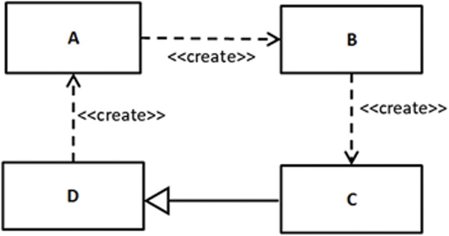
Figure 8: Unsatisfied dependency relationships
Consequences are an important part of verification, where new knowledge is inferred from existing knowledge. Sometimes properties of a model are not explicitly defined [49]. Fig. 11 shows a class model with three classes connected through dependency. Syntactically, the model specifies that when the Booking class instance is created, it creates an instance of the Payment class, which creates an instance of the Transaction class, as shown in Fig. 12. However, semantically, the model specifies that the Booking class instance indirectly creates an instance of the Transaction class due to the transitive characteristic of the create dependency. Fig. 13 shows that a link has been established between the Booking and Transaction classes by the create dependency after performing inference. Fig. 14 shows the outcome in the ontology editor Protégé.
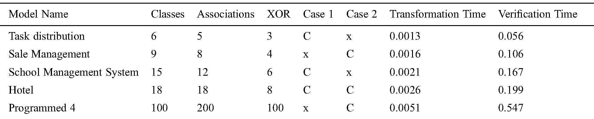
In order to check the efficiency of the proposed method when the number of classes and constraints increase, experiments are performed on different UML class models through the proposed approach. The total verification time is measured for every model and compared to the UMLtoCSP and Alloy tools. The correlation between model size/complexity and execution time is examined. UMLtoCSP does not support 64-bit architecture, so all experiments are performed on a 32-bit core2Duo 1.34 processor with 2 GB RAM. The results show that the proposed method is efficient and can verify a large and complex model within a few seconds. Tab. 1 shows the verification times of different XOR models. For the first model “tasks distribution”, the proposed method verified an average 0.056 seconds with six classes and three XOR associations. For the “sale management” model, it took on average 0.106 seconds with nine classes and four XOR association constraints. For the “school management” system, it took an average 0.167 seconds with 15 classes and 6 XOR associations. For the “hotel” model, it took on average 0.199 seconds. To check the performance of the method on a large model, an experiment on “Programmed 4” with 100 classes, 200 associations and 100 XOR constraints was performed. This took an average of 0.547 seconds.
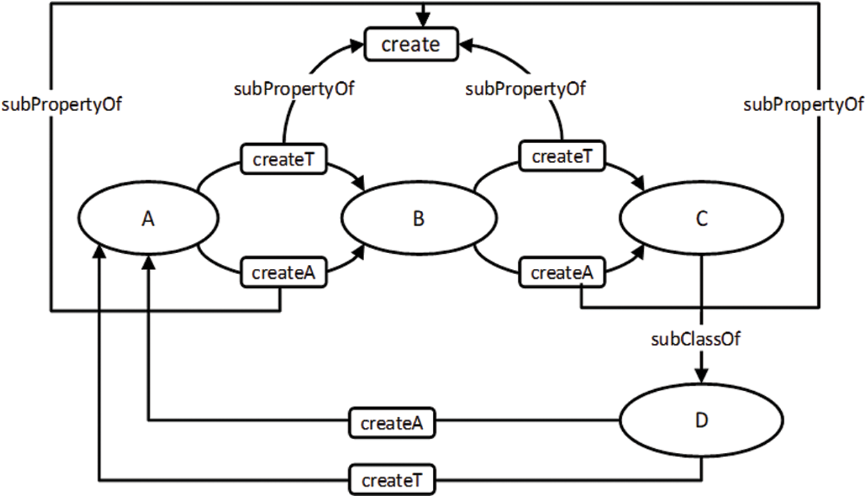
Figure 9: Ontology graph before the inference of the UML class model which is presented in Fig. 8
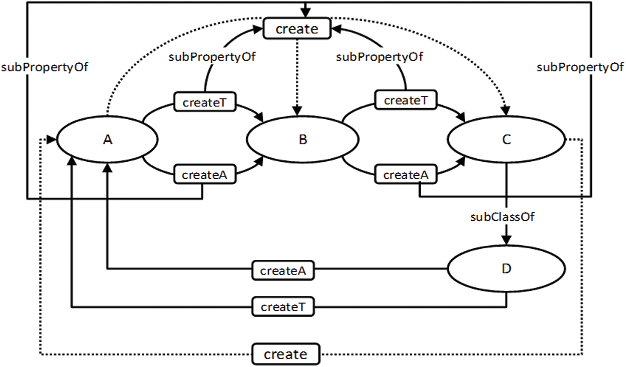
Figure 10: Ontology graph after the inference of the UML class model which is presented in Fig. 8
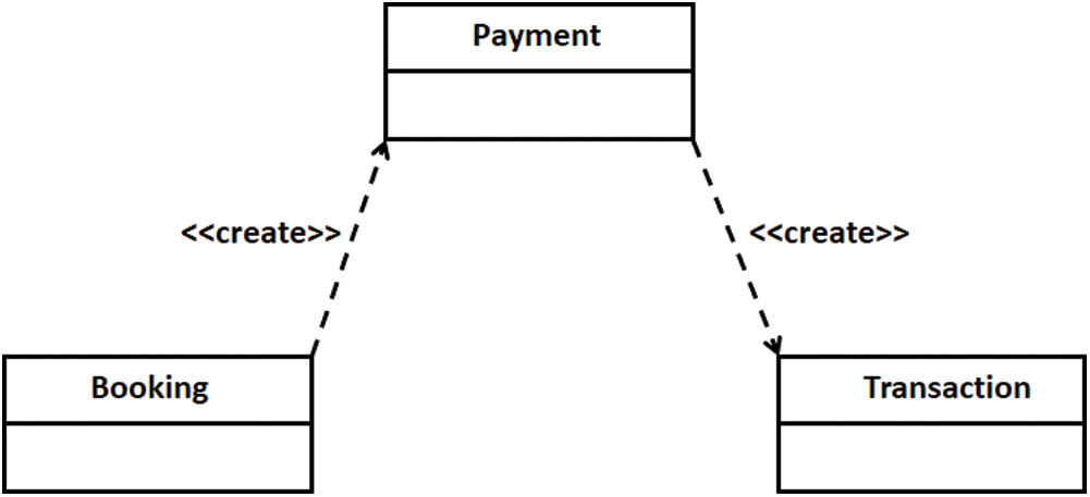
Figure 11: A partial UML class model of the booking system
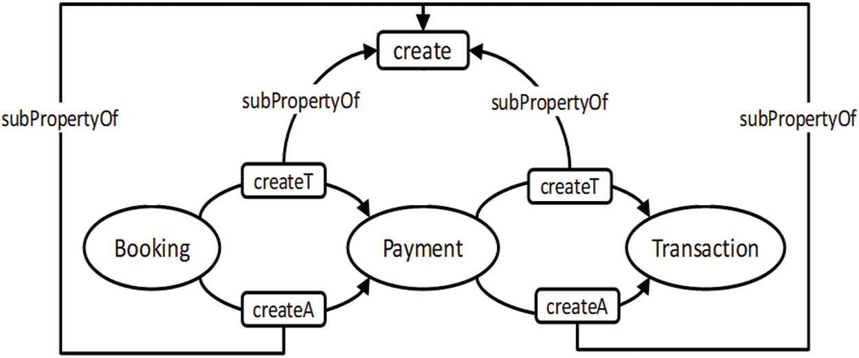
Figure 12: Ontology graph of partial UML class model of the booking system
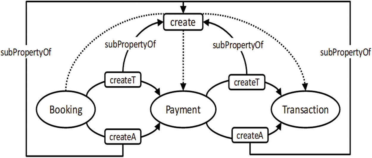
Figure 13: Ontology graph of booking system UML class model after inference
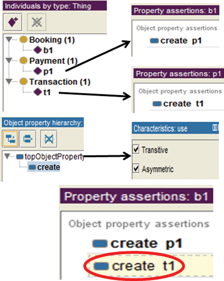
Figure 14: Booking system UML class model inference result in Protégé
Table 1: XOR model experiment results
The comparative results of verification methods with the proposed method are shown in Fig. 15, where the x-axis indicates UML class models and the y-axis is the total verification time in seconds. The results illustrate the proposed method is marginally more efficient than UMLtoCSP and Alloy and has additional benefits:
1. XOR constraints are automatically formalized in the ontology for verification. UMLtoCSP and Alloy do not support XOR constraints, and these were input manually by the designers in OCL.
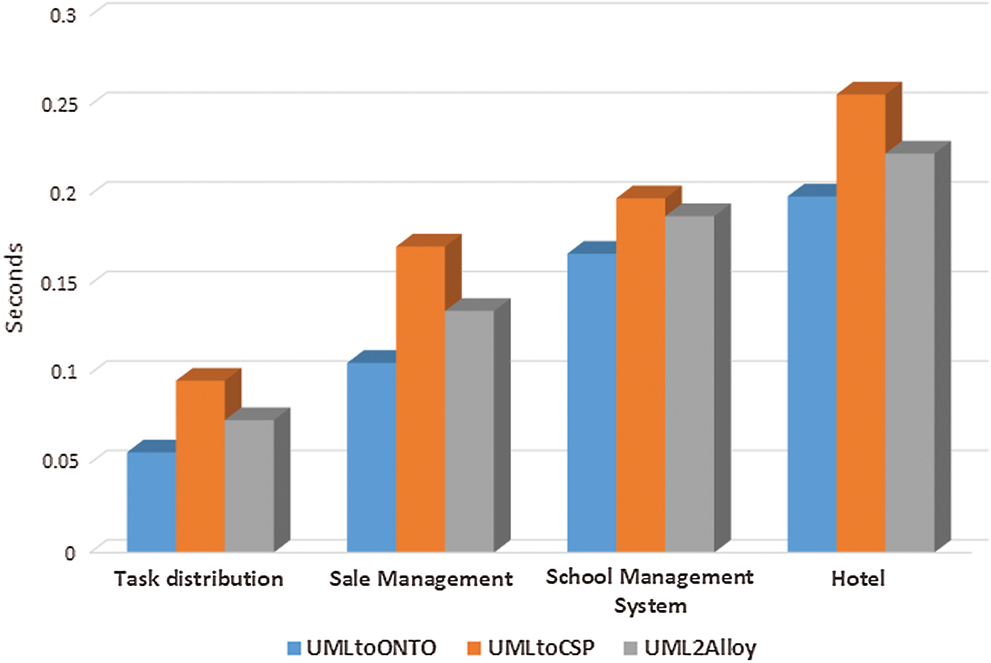
Figure 15: Comparison of different verification methods
2. UMLtoCSP and Alloy support bounded model checking within the limited search space, whereas our proposed approach supports unbounded model checking.
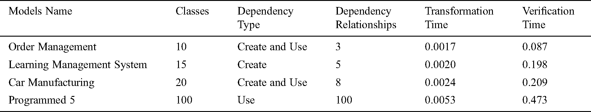
Tab. 2 shows the average execution time required to check the satisfiability and consequences of dependency relationships. For the first model “order management”, the proposed method took an average 0.087 seconds with 10 classes and 3 dependency relationships. For the “learning management” system, it took on average 0.198 seconds with 15 classes and 5 dependency relationships. For “car manufacturing”, it took an average 0.209 seconds with 20 classes and 8 dependency relationships. For “Programmed 5”, it took an average 0.473 seconds with 100 classes and 100 dependency relationships. UML class models with hundreds of dependency relationships and XOR associations are difficult to verify, because in real life, it is rare that a class diagram has as many constraints as “Programmed 4” and “Programmed 5” which demonstrate the efficiency and scalability of the proposed method.
Table 2: Experiment result of the dependency relationships
Model verification is involved in many software methodologies, such as Agile, MDA, and Rational Unified Process (RUP). These check the model for bugs. The most important UML model, the UML class model, is used in analysis as well as design. In previous work, several elements of the UML class model were checked by various methods, while some important elements, such as XOR constraints and dependency relationships, were never checked. In this paper, we have proposed an ontology-based transformation and verification of the UML class model for unsupported elements such as XOR constraints and dependency relationships. These transformations map XOR constraints and dependency relationships to an ontology so as to analyze various correctness properties such as satisfiability, consistency and consequences. The proposed method has the benefit of various efficient reasoners that work on large ontology models in an acceptable time. Our future work will incorporate the transformation of OCL constraints and support to other UML class model elements.
Funding Statement: The authors express their gratitude to the ministry of education and the deanship of scientific research of Najran University, Kingdom of Saudi Arabia, for financial and technical support under code number NU/ESCI/17/098.
Conflicts of Interest: The authors declare that they have no conflicts of interest to report regarding the present study.
1. N. H. Hussein and A. Khalid. (2016). “A survey of cloud computing security challenges and solutions,” International Journal of Computer Science and Information Security, vol. 14, no. 1, pp. 52. [Google Scholar]
2. Technica, “Software bug granted early release to more than 3,200 us prisoners,” 2015. Available https://arstechnica.com/tech-policy/2015/12/software-bug-granted-early-release-to-more-than-3200-us-prisoners/. Accessed: 2020-05-28. [Google Scholar]
3. P. M. Defense. (1992). “Software problem led to system failure at Dhahran, Saudi Arabia. US GAO Reports, report no. GAO/IMTEC-92-26. [Google Scholar]
4. K. Erdil, E. Finn, K. Keating, J. Meattle, S. Park et al. (2003). , “Software maintenance as part of the software life cycle,” Comp180: Software Engineering Project, vol. 1, pp. 1–49. [Google Scholar]
5. I. Traore and D. B. Aredo. (2004). “Enhancing structured review with model-based verification,” IEEE Transactions on Software Engineering, vol. 30, no. 11, pp. 736–753. [Google Scholar]
6. X. Oriol and E. Teniente. (2017). “Simplification of UML/OCL schemas for efficient reasoning,” Journal of Systems and Software, vol. 128, pp. 130–149. [Google Scholar]
7. M. Kardoš and M. Drozdová. (2010). “Analytical method of CIM to PI, transformation in Model Driven Architecture (MDA),” Journal of Information and Organizational Sciences, vol. 34, no. 1, pp. 89–99. [Google Scholar]
8. S. Kent. (2002). “Model driven engineering,” in International Conference on Integrated Formal Methods, Berlin, Heidelberg: Springer, pp. 286–298. [Google Scholar]
9. A. Shaikh and U. K. Wiil. (2018). “Overview of slicing and feedback techniques for efficient verification of UML/OCL class diagrams,” IEEE Access, vol. 6, pp. 23864–23882. [Google Scholar]
10. J. L. F. Alemán and A. T. Álvarez. (2000). “Can intuition become rigorous? foundations for UML model verification tools,” in Proceedings 11th International Symposium on Software Reliability Engineering, IEEE, San Jose, California, pp. 344–355. [Google Scholar]
11. A. Shaikh, R. Clarisó, U. K. Wiil and N. Memon. (2010). “Verification-driven slicing of UML/OCL models,” in Proceedings of the IEEE/ACM International Conference on Automated Software Engineering, Antwerp, Belgium, ACM, pp. 185–194. [Google Scholar]
12. M. Balaban, A. Maraee, A. Sturm and P. Jelnov. (2015). “A pattern-based approach for improving model quality,” Software & Systems Modeling, vol. 14, no. 4, pp. 1527–1555. [Google Scholar]
13. M. Cadoli, D. Calvanese, G. De Giacomo and T. Mancini. (2004). “Finite satisfiability of UML class diagrams by constraint programming,” CSP Techniques with Immediate Application (CSPIA), vol. 2, pp. 2–16. [Google Scholar]
14. H. Malgouyres and G. Motet. (2006). “A UML model consistency verification approach based on meta-modeling formalization,” in Proceedings of the 2006 ACM Symposium on Applied Computing, Dijon France, pp. 1804–1809. [Google Scholar]
15. M. Singh, A. K. Sharma and R. Saxena. (2016). “An UML+Z framework for validating and verifying the static aspect of safety critical system,” Procedia Computer Science, vol. 85, pp. 352–361. [Google Scholar]
16. R. Clarisó, C. A. González and J. Cabot. (2015). “Towards domain refinement for UML/OCL bounded verification,” in International Conference on Software Engineering and Formal Methods Collocated Workshops, York, UK: Springer, pp. 108–114. [Google Scholar]
17. M. H. Awaad, H. Krauss and H. D. Schmatz. (1978). “Advanced praise for the unified modeling language reference manual reading,” Zentralblatt für Bakteriologie, Parasitenkunde, Infektionskrankheiten und Hygiene. Erste Abteilung Originale. Reihe A: Medizinische Mikrobiologie und Parasitologie, Pontifical Bolivarian University, Colombia, vol. 240. [Google Scholar]
18. G. Booch, I. Jacobson and J. Rumbaugh. (1996). “The unified modeling language for object-oriented development. Unified Modeling Language, V. 0.91 Addendum, pp. 1–35. [Google Scholar]
19. A. Shaikh, U. K. Wiil and N. Memon. (2011). “Evaluation of tools and slicing techniques for efficient verification of UML/OCL class diagrams,” Advances in Software Engineering, vol. 2011, pp. 1–18. [Google Scholar]
20. A. N. M. C. Files. (2013). “Omg unified modeling language tm (omg UML),” Object Management Group, version 2.5, pp. 1–752. [Google Scholar]
21. O.M. Group. (2007). “UML Constraint.” version 2.5, . Available: http://www.uml-diagrams.org/constraint.html. [Google Scholar]
22. R. Pandey. (2011). “Object constraint language (OCL) past, present and future,” ACM SIGSOFT Software Engineering Notes, vol. 36, no. 1, pp. 1–4. [Google Scholar]
23. H. Hussmann, B. Demuth and F. Finger. (2000). “Modular architecture for a toolset supporting OCL,” in International Conference on the Unified Modeling Language, Berlin, Heidelberg: Springer, pp. 278–293. [Google Scholar]
24. A. Fish, J. Howse, G. Taentzer and J. Winkelmann. (2005). “Two visualizations of OCL: A comparison,” University of Brighton, Technical Report no. VMG. 5. [Google Scholar]
25. I. S. Bajwa and M. A. Shahzada. (2017). “Automated generation of OCL constraints: NL based approach vs pattern based approach,” Mehran University Research Journal of Engineering and Technology, vol. 36, no. 2, pp. 243–254. [Google Scholar]
26. R. Korytkowski. (2016). “Thoughts about OCL - The Object Constraint Language,” version 1, . Available: http://www.shiftedup.com/2016/02/05/thoughts-about-ocl-the-object-constraint-language.
27. I. S. Bajwa, M. Lee and B. Bordbar. (2012). “Translating natural language constraints to OCL,” Journal of King Saud University - Computer and Information Sciences, vol. 24, no. 2, pp. 117–128. [Google Scholar]
28. P. H. Stephan Grimm and A. Abecker. (2007). “Knowledge representation and ontologies,” Semantic Web Services: Concepts Technologies, and Applications, vol. 1, pp. 51–105. [Google Scholar]
29. F. S. Parreiras and S. Staab. (2010). “Using ontologies with UML class-based modeling: The two use approach,” Data & Knowledge Engineering, vol. 69, no. 11, pp. 1194–1207. [Google Scholar]
30. J. Cabot and R. Clarisó. (2008). “UML/OCL verification in practice,” in ChaMDE Workshop Proceedings: International Workshop on Challenges in Model-Driven Software Engineering, Toulouse, France, pp. 31–35. [Google Scholar]
31. D. Berardi, D. Calvanese and G. De Giacomo. (2005). “Reasoning on UML class diagrams,” Artificial Intelligence, vol. 168, no. 1–2, pp. 70–118. [Google Scholar]
32. R. France, A. Evans, K. Lano and B. Rumpe. (1998). “The UML as a formal modeling notation,” Computer Standards & Interfaces, vol. 19, no. 7, pp. 325–334. [Google Scholar]
33. H. Ledang and J. Souquières. (2001). “Integrating UML and B specification techniques,” in The Informatik 2001 Workshop on Integrating Diagrammatic and Formal Specification Techniques. HAL, Vienna, Austria, 1–8. [Google Scholar]
34. K. Anastasakis, B. Bordbar, G. Georg and I. Ray. (2010). “On challenges of model transformation from UML to alloy,” Software & Systems Modeling, vol. 9, no. 1, pp. 69. [Google Scholar]
35. B. Bordbar and K. Anastasakis. (2005). “UML2alloy: A tool for lightweight modelling of discrete event systems,” in International Conference Applied Computing, Algarve, Portugal: IADIS, pp. 209–216. [Google Scholar]
36. A. Maraee, V. Makarenkov and B. Balaban. (2008). “Efficient recognition and detection of finite satisfiability problems in UML class diagrams: Handling constrained generalization sets, qualifiers and association class constraints,” in Model Co-evolution and Consistency Management, Berlin, Heidelberg: Springer, pp. 120–123. [Google Scholar]
37. S. K. Kim and D. Carrington. (2000). “A formal mapping between UML models and object-Z specifications,” in International Conference of B and Z Users, York, UK: Springer. [Google Scholar]
38. S. K. Kim and D. Carrington. (2005). “A formal v&v framework for UML models based on model transformation techniques,” in Proceedings of the 2nd MoDeVa Workshop - Model Design and Validation, Montego Bay, Jamaica: Springer, pp. 1–7. [Google Scholar]
39. H. Ledang. (2001). “Automatic translation from UML specifications to B,” in Proceedings 16th Annual International Conference on Automated Software Engineering (ASE 2001San Diego, USA: IEEE, pp. 436–442. [Google Scholar]
40. B. Pérez and I. Porres. (2019). “Reasoning about UML/OCL class diagrams using constraint logic programming and formula,” Information Systems, vol. 81, pp. 152–177. [Google Scholar]
41. J. Cabot and E. Teniente. (2009). “Incremental integrity checking of UML/OCL conceptual schemas,” Journal of Systems and Software, vol. 82, no. 9, pp. 1459–1478. [Google Scholar]
42. M. Balaban and A. Maraee. (2013). “Finite satisfiability of UML class diagrams with constrained class hierarchy,” ACM Transactions on Software Engineering and Methodology (TOSEM), vol. 22, no. 3, pp. 1–42. [Google Scholar]
43. A. Maraee and M. Balaban. (2009). “Efficient recognition of finite satisfiability in UML class diagrams: Strengthening by propagation of disjoint constraints,” in International Conference on Model-Based Systems Engineering, Haifa, Israel: IEEE, pp. 1–8. [Google Scholar]
44. J. C. Robert and C. A. Gonzalez. (2020). “Incremental verification of UML/OCL models,” Journal of Object Technology, vol. 19, pp. 1–16. [Google Scholar]
45. S. Maoz, J. O. Ringert and B. Rumpe. (2011). “Cd2alloy: Class diagrams analysis using alloy revisited,” in International Conference on Model Driven Engineering Languages and Systems, Wellington, New Zealand: Springer, pp. 592–607. [Google Scholar]
46. W. Xu, A. Dilo, S. Zlatanova and P. van Oosterom. (2008). “Modelling emergency response processes: Comparative study on OWL and UML,” Information Systems for Crisis Response and Management, Harbin Engineering University, 493–504. [Google Scholar]
47. A. Belghiat and M. Bourahla. (2012). “From UML class diagrams to owl ontologies: A graph transformation-based approach,” in International Conference on Web and Information Technologies (ICWITSidi Bel Abbes, Algeria: CEUR-WS, pp. 330–335. [Google Scholar]
48. A. Shaikh and U. K. Wiil. (2014). “A feedback technique for unsatisfiable UML/OCL class diagrams,” Software: Practice and Experience, vol. 44, no. 11, pp. 1379–1393. [Google Scholar]
49. S. Cook. (2017). “Designing precise and flexible graphical modelling languages for software development,” PhD thesis. Middlesex University. [Google Scholar]
 | This work is licensed under a Creative Commons Attribution 4.0 International License, which permits unrestricted use, distribution, and reproduction in any medium, provided the original work is properly cited. |