DOI:10.32604/iasc.2020.012268
| Intelligent Automation & Soft Computing DOI:10.32604/iasc.2020.012268 | |
| Article |
Research into Visual Servo Based Haptic Feedback Teleoperation
1School of Mechanical and Aerospace Engineering, Jilin University, Changchun, 130000, China
2Department of Mechanical Engineering, Clemson University, Clemson, 25633, US
*Corresponding author: Lingtao Huang. Email: hlt@jlu.edu.cn
Received: 23 June 2020; Accepted: 10 August 2020
Abstract: To overcome the problem that a teleoperation system loses robustness when the target moves outside the robot’s visual field or it is far away from the desired position, and to improve the operability and controllability of a master-slave teleoperation system, we present an image servo based haptic feedback (ISBHF) control method for teleoperating. The ISBHF control method involves extracting target feature points and constructing image servo based virtual force. First, the image characteristics of the environment and targets are identified and extracted by a 3D reconstruction method. A composite image Jacobian matrix is used to construct virtual guidance force based on the target’s image error. Then, the virtual force is provided for the operator through two joysticks which prevents the target image from drifting out of the visual field of the camera. We conducted experiments to confirm the validity and efficacy of the ISBHF control method. We found that human manipulation may cause the target image to deviate from the camera view, but the image servo based virtual force guides the operator to calibrate the target image back to the center view. The ISBHF control method can easily guide the robot to track the target and prevent image feature points deviating from the camera view. Teleoperation can be improved by combination of the robot visual sensory information and human haptic perception with the ISBHF control method. The ISBHF control method is favorable for the robot to avoid the blind operation of human and the collision with other obstacles.
Keywords: Visual servo; composite image; Jacobian matrix; virtual force; haptic feedback
Master slave teleoperation robots are well suited to high-temperature, high-pressure, or suffocating environments, such as those in the deep sea, underground, and outer space [1,2]. Operators manipulate such robots with the aid of feedback in the form of images, sound, and haptic information received from the unpredictable and remote working environment without a comprehensive perception of the robot operating area [2]. In vision-based teleoperation, which has been very widely adopted, operators manipulate robot relying on their own senses through the images captured by the end-effector camera. The installation of eye-in-hand camera would provide the operator with a direct visual sense of the robot position [3–6]. However, human perception tends to lack control of security and accuracy [1,2]; for instance, the operator could consider an optimized routine, which is based on the current perspective view, although he/she could find and adopt an alternative that would be the better routine immediately after. In addition, targets tend to fall outside the visual view of the camera and prove difficult to recapture in the continuously changing camera view [1,2,7]. The deviations and collisions that result from this control method adversely affect the operating efficiency and safety of the robot. These are caused by the operator’s limited senses, given that the display is the only information available.
We proposed a 3D vision based kinesthesic teaching control strategy [8,9]. It is based on the artificial potential field method [10], whereby a virtual force potential field function is constructed based on the position of obstacles and targets, to make predictions regarding trajectory planning. The method uses position-based visual servo forces to manipulate a slave robot. It converts part of the vision information into force sensations that allows operators to share control while manipulating the robot. However, it needs the prediction of the target position, and the acquisition of target image data will be interrupted with the target moving out of the camera’s visual field. When this situation occurs, the operator still has to rely on his/her own senses.
The image based visual servo method establishes an image Jacobian matrix, which reflects the control relationship between the image servo errors and the end-effector position variation, through the application of robot vision control theory [6,10–12]. The method focuses on the target image errors and is able to restrict the target image in the camera view. It does not need an estimate of the target position nor an accurate geometry reconstruction for the working environment [9–11]. In addition, researchers can obtain an online estimate of the image Jacobian matrix, which prevents the singularities and inevitable errors caused by camera calibration or visual depth estimation [11–15]. However, the image based visual servo method can only be applied in relatively small areas. If the target moves outside the robot’s field of view or is far away from the desired position, the system will lose robustness.
Consequently, we present the ISBHF control method. It captures an image of a target in its initial position and then establishes an image Jacobian matrix relationship between the image servo errors and the robot position variation. Through the position servo based haptic force (PSBHS) control method, we construct the image servo error based virtual force (virtual force), which includes virtual repulsive force and virtual attractive force. The ISBHF control method can guarantee the target image to be restricted in the center view of camera as well as the end-effector to reach target objects. In addition, we use the RLS algorithm to estimate the Jacobian Matrix without help of camera calibration. On the other hand, the virtual force is fed back to the joysticks and is incorporated with human operation to enhance the reliability of system. As a consequence, teleoperation could be improved by combination of the robot visual sensory information and human haptic perception.
The paper is divided into six sections. Section 2 explains the control method composition and principle. Section 3 explains the method of recognizing and extracting target objects from an image, and how the acquired information is used to estimate the image servo based composite image Jacobian matrix with an RLS algorithm. Section 4 describes how the virtual force is constructed with an estimated composite image Jacobian matrix and then returned to the operator. Section 5 describes experiments that were conducted to verify the validity and efficacy of the ISBHF control method for helping the operator and preventing a target from deviating out of the visual field of the camera. Section 6 concludes this paper.
2 Composition and Principle of Control System
A visual servo based virtual force feedback teleoperation control system transforms the two-dimensional image position deviation information of a target object into force signals and transmits force signals to a manual device as virtual attractive force and virtual repulsive force. These forces prompt the operator to manipulate a haptic control device in order to complete a teleoperation task, as shown in Fig. 1.
Figure 1: Visual servo based virtual force feedback teleoperation control system
The teleoperation control system consists of the master manipulation system and the slave control system. The slave control system includes a 4-DOF robot, servo motor control modules, a Bumblebee binocular camera (Point Grey Research, Canada) on an end-effector (used to identify and extract the feature points of the target object), a Kinect camera (Microsoft, US; placed over the working environment to acquire 3D data through the application of a point cloud matching technique [16–19]) and a control computer (computer 1 in Fig. 1). The master manipulation system consists of two joysticks (Logitech WingMan force feedback joysticks) and a control computer (computer 2 in Fig. 1). Computer 2 receives the information about the robot and image, and then rebuilds the robot and objects in virtual space. Meanwhile, Computer 2 sends the joystick information to Computer 1. The operator manipulates two 2-DOF force feedback joysticks to perform position control for the slave robot. Each joystick contains two motors so that the operator can perceive in two directions. The manipulation is undertaken using the image produced by Computer 2, which reconstructs an image of the 3D working environment.
3 Composite Jacobian Matrix for Image
The creation of virtual force requires the identification and extraction of image characteristic information for the target objects. The Bumblebee binocular camera is used to identify a target object and acquire information on feature points. In addition, the Kinect camera collects video images and depth information of field to enable the regeneration of a 3D virtual working environment, which provides a visual interface to improve the manipulation by the operator. These were specifically demonstrated in our period research in [8,9].
1) Acquisition and Extraction of Targets and Environment Graphic Information
For this study, we assume that there is a distinctive differentiation in terms of color, gradation, and texture between the target objects and working environment background. Given that the work addressed in this section is mostly a repetition of our period research, we provide only a brief introduction to the identification, extraction and reconstruction processes.
The image information extraction and working environment reconstruction process began with the establishment of a position relationship between the robot arms, cameras and working environment. Binarization segmentation between the targets and the working environment background was acquired according to the local dynamic threshold value for the color and gradation of each pixel. Microscopic pores caused by noise were removed from the binary image by the application of an inflation-corrosion algorithm. Chaotic area less than 100 pixels were removed after each target object had been labeled in the image. Rough contour polygon areas in the targets were extracted through the application of an image segmentation and fusion algorithm. Polygon vertexes were taken as feature points of the targets. The target objects were separated from the working environment background with a geometric and color-based regional growth method. Then, 3D objects for each segment field were constructed with processed point cloud data according to the Power Crust algorithm [20,21]. All constructed 3D objects were placed together to merge the integration of the virtual environment. The extracted key points of the targets are shown in Fig. 2.
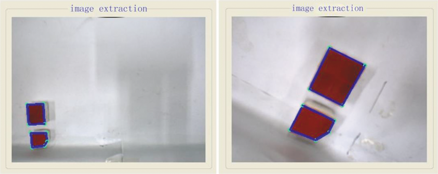
Figure 2: Initial (left) and desired (right) position of targets’ image feature points
The virtual force is calculated using a composite image Jacobian matrix. The following parts describe the deduction and value estimation of the composite Jacobian matrix according to the position and orientation of the end-effector.
2) Establishment of Composite Image Jacobian Matrix
A pinhole model of the hand camera is shown in Fig. 3.
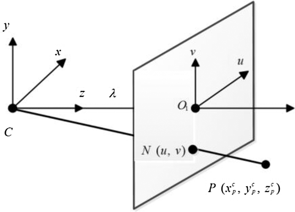
Figure 3: Pinhole model of hand camera
 denotes the local coordinate system in which the hand camera is located, while
  denotes the camera’s two-dimensional image projecting plane. Further,
  is the focal length of the Bumblebee binocular camera,
  is a key point of a target object defined as
  in the camera located coordinate system.
  , defined as
  , is the projection of point Pin plane
  . According to the camera pinhole model, the position of a target point in plane
  is related to that in the camera located coordinate system, as follows:

The derivation of the above yields:
The composite image Jacobian matrix  contributes to the relationship between an feature point’s position gradient in the image plane and the hand camera’s velocity relative to the robot target object coordinate system
  . According to the definition, the relationship is described as
 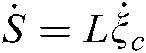 , which can be explained as:

 represents the feature point’s position in the camera’s two-dimensional image projecting plane
  ;
;  is the velocity of the feature point projected in the two-dimensional image plane, and
  , where
  ,
,  , denotes the position and orientation changes of the hand camera relative to the target object coordinate system, respectively.
According to the definition of the composite image Jacobian matrix, the gradient of each directional image position is described for every dimensional position of the hand camera. Thus, we define  as:
as:
 and
and  , as has been described, represent the image position of a feature point
  .
.  ,
,  denotes the position and orientation of the hand camera relative to the target object coordinate system
  , respectively.
The translational velocity of point  relative to the hand camera can be calculated from the kinematic relationship, as follows:

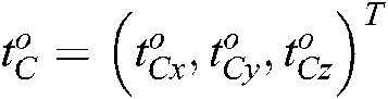
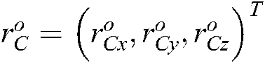
where  ,
,  denotes the position and orientation changes of target object relative to the hand camera located coordinate system, respectively. This can be detailed as:
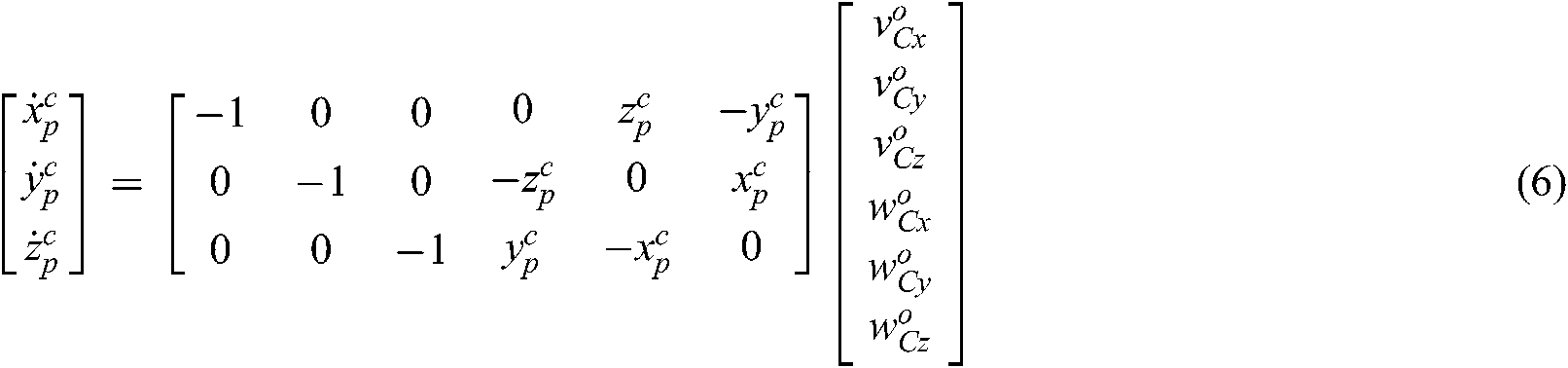
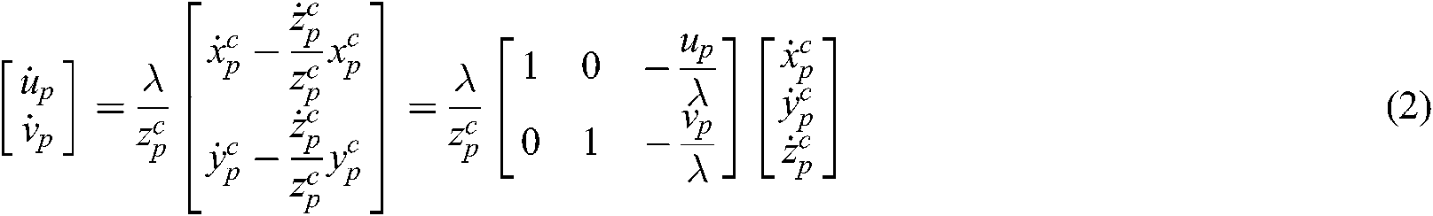
According to Eqs. (2) and (6), the velocity of the image feature point  in the hand camera image plane can be described as:

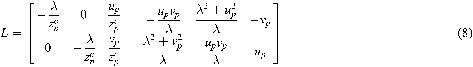
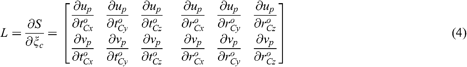
Considering the offset between the camera and robot end-effector coordinate system, the Jacobian matrix  , which contributes to the relationship between the speed of the hand camera’s movement and the gradient of the end-effector’s posture is given as:

where  contributes to the velocity vector of the end-effector relative to the target object coordinate system.
The angular velocity  of each joint has a Jacobian matrix relationship with end-effector posture variation rate
  , which could be depicted as:
where  ,
,  (j=1,L,4) are the
  th robot joint angles.
The relationship between the velocity vector of feature point  and the angular velocity of joints
  can be defined as:

where 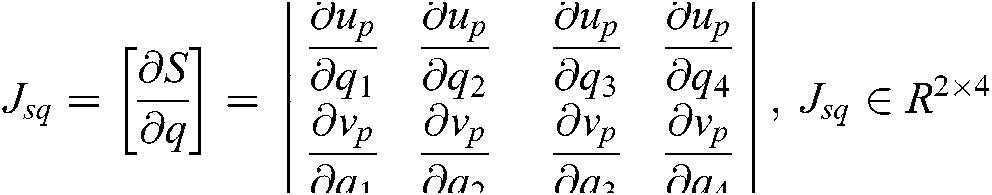 , the composite image Jacobian matrix of a single feature point is calculated based on Eqs. (8)–(11), as follow:

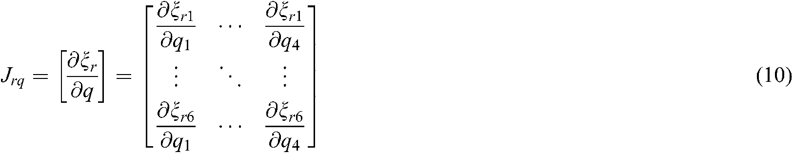
Thus, the composite image Jacobian matrix for multiple feature points can be described as:
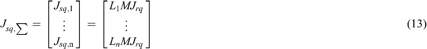
where  represents the
  feature point’s composite image Jacobian matrix, and it is real matrix,
  is the feature point’s image Jacobian matrix.
3) Estimation of Composite Image Jacobian Matrix
To determine the composite image Jacobian matrix, we require the focal length of the hand camera and the depth of image parameters. However, camera calibration and image depth accuracy greatly affect the precision of the composite Jacobian matrix values. Thus, a direct estimation of the composite image Jacobian matrix is neither efficient nor accurate for current ISBHF control strategy.
The recursive least square algorithm (RLS) exploits the exponential weighted average to estimate a composite image Jacobian matrix based on the dynamic quasi-newton method. The iteration of the composite image Jacobian matrix with the RLS algorithm can thus be described as follows:


where  ,
,  represents the displacement differentials of the robot joints in each step;
  is the error matrix between the desired image position and the actual position;
  is the forgetting factor, and
  is the covariance matrix. A forgetting factor between 0 and 1 can be set. However, if
  is equal to 1, the new information is averaged with the previous data, implying that the value stability of
  would fluctuate greatly with the effect of noise as a result of the infinite divergence of the composite image Jacobian matrix. This would lead to severe safety problems in the control of the position of the robot joints. If
  approaches 0, previous data is given less weight in the Jacobian estimation, which leads to more iterative steps and more time. Finally, the value of
  is determined to be 0.5.
To reduce the iteration of the composite image Jacobian matrix,  is directly estimated with four steps of linear independent displacement control
  to initialize the matrix. The initialization of
  is:
is:
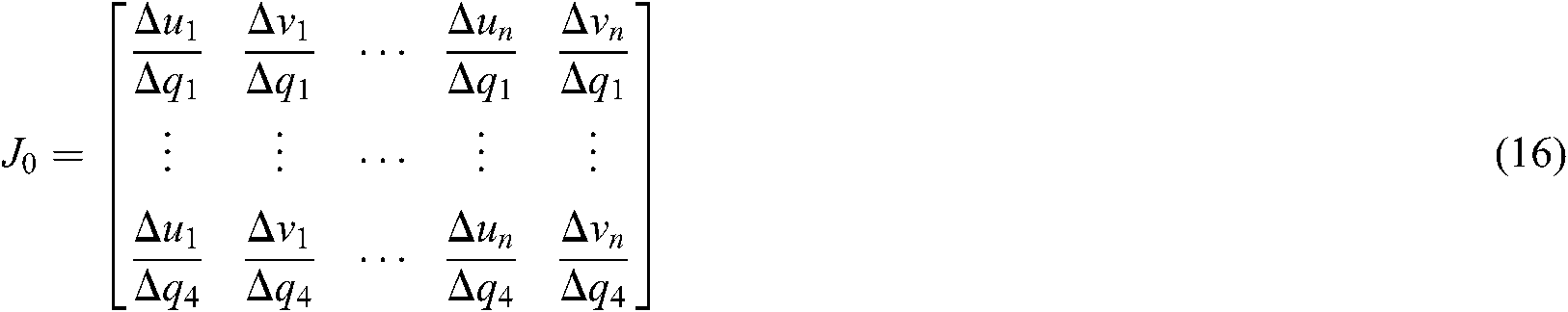
where  and
and  are the respective displacements of every robot joint in each of the four steps.
  and
and  are the finalized respective image error differentials of the target feature points in the image plane. The dynamic estimation of the composite image Jacobian matrix is conducted according to Eqs. (14) and (15) after the initialization.
4 Proposed Method for Visual Servo Based Force Control
We incorporated a visual servo method into the position-based force guidance strategy to construct the virtual force for the teleoperation system based on image servo error. We describe the construction of the virtual attractive and repulsive force model in this section. This method guarantees the convergence of the end-effector’s movement trajectory to the desired position. In addition, the visual servo force resists the deviation of the target image from center field of the camera view when the robot end-effector is guided with the virtual force.
1) Image Servo Based Virtual Repulsive Force Model
The image acquisition and multiple feature point extraction for target objects are conducted with the Bumblebee camera as part of the control process.  denotes the current position of the target’s multiple feature point defined in Section 3.2.
  means the desired position in image plane. They are extended as follows:


where  ,
,  ,
,  .
.  and
and  are the minimum and maximum boundaries of pixels
  respectively.
  and
and  are the minimum and maximum boundary values of pixels
  respectively.
  and
and  denote the size of the image margin and both are positive.
  is defined as the marginal area of the feature point’s image, and
  means the shadow area in Fig. 4. The image-based repulsive force equation
  for the target is constructed based on the feature points’ image boundaries using the artificial potential field method.
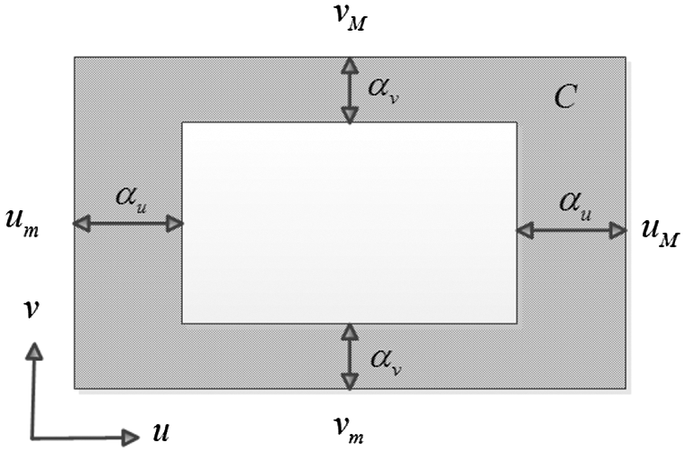
Figure 4: Image boundary diagram
The repulsive potential energy equation  describes the current potential energy of the image position [22], and provides an estimation of the stability of the target object image within the visual field of the camera. This equation is defined as:
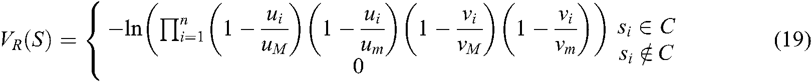
where 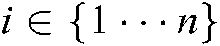 represents the number of target feature points.
 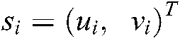 , as has been defined, is the feature point’s position. Define
  . The transposed first and second gradient vector equation are obtained as Eqs. (20) and (21):

where 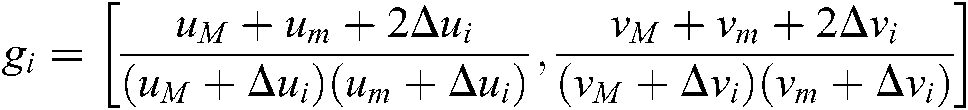 .
.
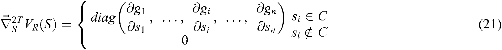
where 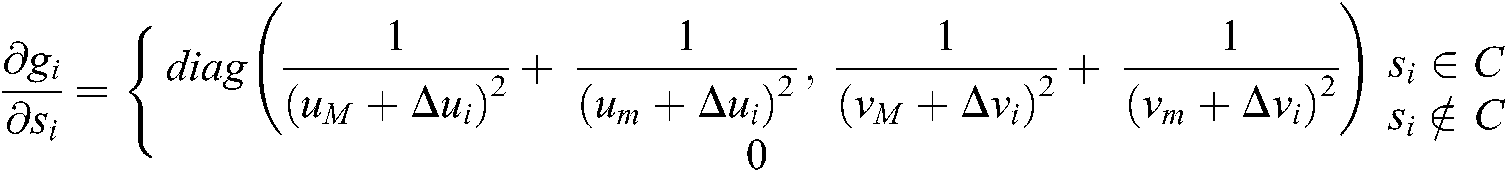 .
.  is positive definite, so the Eq. (19) is convex.
  increases significantly when feature points deviate from the desired position in area
  , and becomes zero in
  . As mentioned above,
  means the shadow area in Fig. 4. Without considering
  , the curve of the Eq. (19) is shown as in Fig. 5.
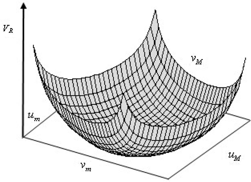
Figure 5: Repulsive potential energy diagram of image feature points
With the negative gradient of the potential equation and composite Jacobian matrix for the image, the image servo based virtual repulsive force  is defined as:

where  is the positive matrix of gain,
  is the pseudo inverse of
  , which is estimated using the RLS algorithm from
  . The repulsive force Eq. (22) decreases as the points move from marginal limit to the center field of the camera view. It ensures all the feature points located in the inner field of view.
2) Image Servo Based Virtual Attractive Force Model
The image servo based virtual attractive force  is constructed with the errors between the desired feature points’ position
  and the current position
  on the basis of the artificial potential field [22]. The attractive potential energy equation is defined as:
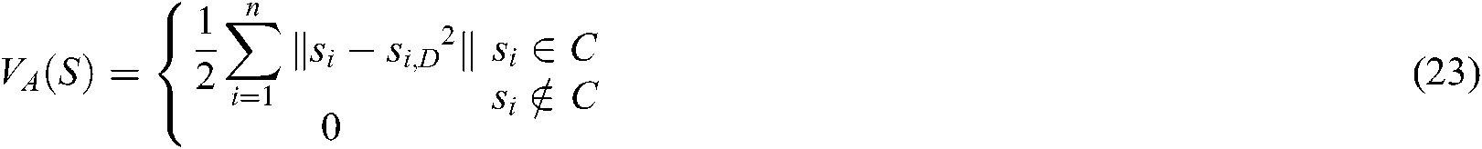
The transposed gradient vector equation is obtained as:


 is positive definite, so the Eq. (23) is convex.
  increases when feature points deviate from the desired position in area
  and becomes zero in
  . The position of the target feature point’s image and robot end-effector approaches the desired position under the guidance of the attractive force:

where  is the positive matrix of gain.
3) Analysis of Image Servo Based Teleoperation Model
The image servo based virtual attractive force and virtual repulsive force are incorporated through the adaptive coefficients,  and
and  . The forces are fed back to the joysticks in the form of haptic signals to guide the operator to control the robot. The feedback guidance force equation can be depicted as:

The operator manipulates the slave robot to reach the desired position with image servo guidance information and control signals from joysticks, as is shown in Fig. 6.
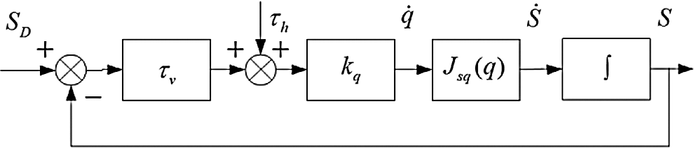
Figure 6: Block diagram of ISBHF control
 and
and  are the respective torques mapped from the operator manipulating force and the feedback virtual force. The incorporated torques on manipulator joints are used to predict velocity and drive the slave robot.
  is the impedance matrix. The state equation of control system could be depicted as:


In the image servo guidance system, the virtual force is generated and is fed back to the joysticks to guide the operator, so while the robot end-effector approaches the target, the target image remains in the center field of the camera view. Namely, the operator does not actively operate the joystick, but the generated virtual force can impel the joystick to guide the operator.  works only in the marginal area
  .
.
In the experiments, the end-effector of a 4-DOF robot was fitted with a Bumblebee binocular camera that was used to identify and extract the image feature points of a red target object. A Kinect camera was installed near the robot to simultaneously acquire a 3D view of the working environment. The graphic computer (Computer 2 in Fig. 1) reconstructed the 3D scene to provide visual guidance, while the computer (Computer 1 in Fig. 1) determined appropriate virtual force to provide haptic guidance. Two joysticks were used to control the teleoperation robot and to provide the operators with virtual force signals. The operator operated the 4–DO robot by the joysticks according to the reconstructed virtual scene and virtual force. Figs. 7 and 8 shows the platform and the interface working environment, respectively.
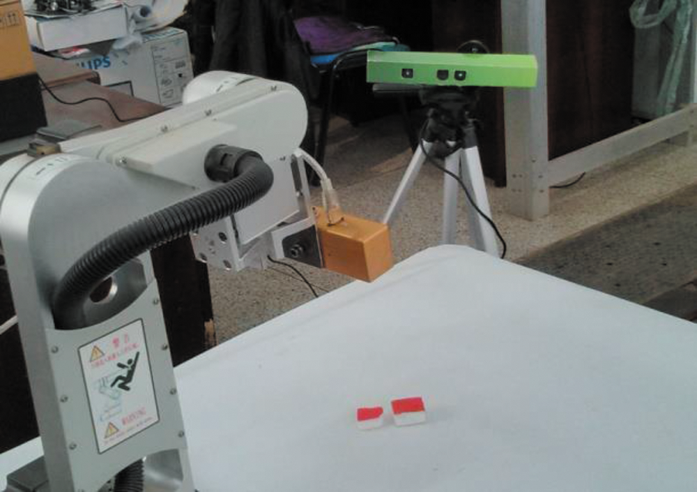
Figure 7: Experiment setup in slave side
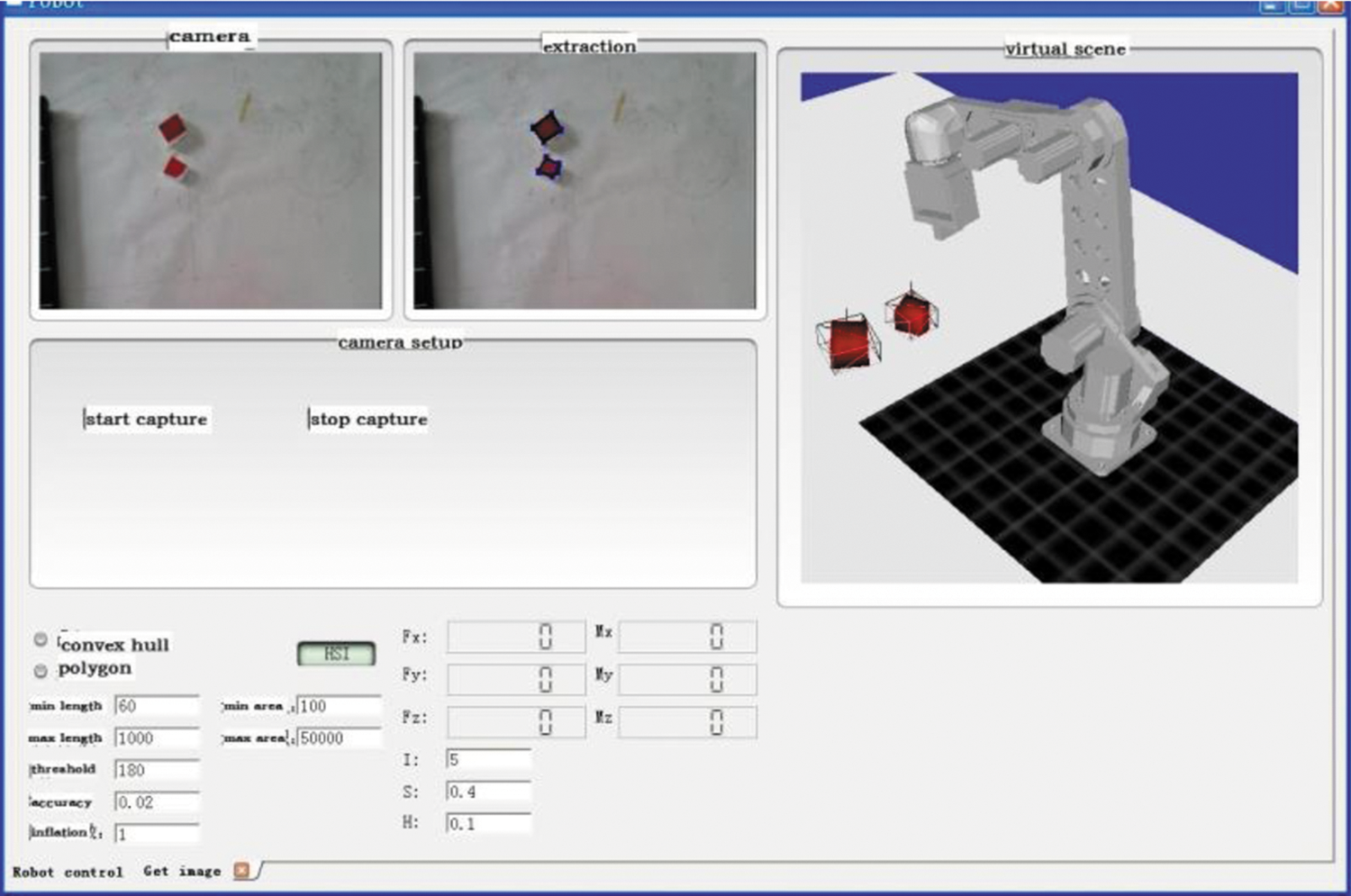
Figure 8: Interface in master side
The ISBHF control method is used to define the desired position and orientation of the robot at the position where the end-effector reached the target object, and the target image feature points move into the center of the camera view. The error threshold  is restricted to 3.0. The robot tracks the targets as the camera collected and extracted the image feature information, until
  . The image servo based virtual force can guarantee that the target object image is constrained to the center of the camera view.
1) Estimation of Virtual Repulsive Force and Virtual Attractive Force
In order to validate the respective efficacy of the virtual repulsive force and virtual attractive force, we compared the image trajectories caused by virtual repulsive force and virtual attractive force, regardless of the effective area function  and
and  , conducted experiments under only the virtual repulsive force or attractive forces guidance without human manipulation, as shown in Fig. 9.
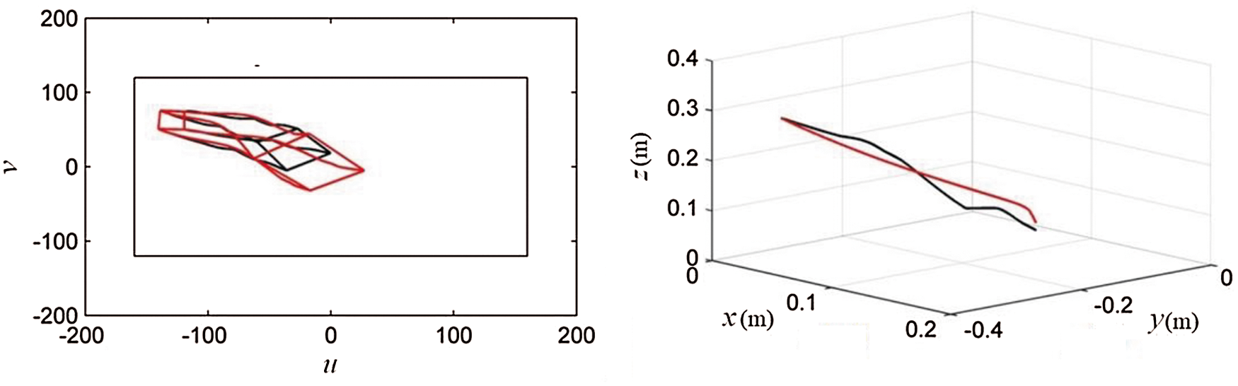
Figure 9: Comparison of feature points (left) and end-effector (right) trajectories between the virtual repulsive force and virtual attractive force
The black curves denote the results guided by the virtual repulsive force, and the red curves mean the results guided by the virtual attractive force in Fig. 9. The coordinate (feature points (left) in Fig. 9) records the trajectories of four feature points in the camera image plane, and the rectangle represents the view boundary lines of the camera. When the feature points’ desired position is fully extended in the camera view, the red curves show smooth feature points and end-effector trajectory. It demonstrates well guidance in z-depth direction by the virtual attractive force.
As a contrast, the control guided by the virtual repulsive force shows instable and divergent trajectory results when all the feature points’ desired position is extended in a full view. It will cause great and instable guidance forces by every single point in the initial control period according to the definition of repulsive force equation. On the other hand, the virtual attractive force will lose its function if the feature points’ desired position is set too close to the center point.
According to teleoperation model in Section 4.3, we needed to incorporate the repulsive and attractive forces. Finally, we made a compromise and set the desired position to be (–41.72, 11.52), (–1.187, 40.21), (–2.652, –39.82) and (40.27, –3.635) through several extensive tests. They can satisfy both the attractive and repulsive force guidance control. In term of the curves in Fig. 9, the feature points and end-effector trajectory can be guided into the desired position with both the attractive and repulsive force guidance control.
2) Comparison between PSBHF and ISBHF
We made a contrast experiment between the PSBHF control method and the ISBHF control method without human manipulation. The obtained trajectories of the target feature points in camera image plane and end-effector trajectory are shown in Fig. 10.
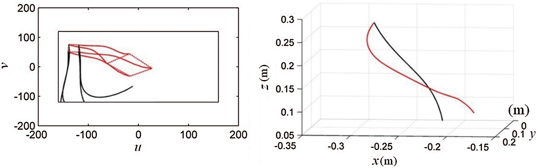
Figure 10: Comparison of feature points (left) and end-effector (right) trajectories between PSBHF and ISBHF
The black curves represent the behavior of feature points and end-effector trajectory under PSBHF control method, while the red ones record the guidance results under ISBHF control method without human manipulation. According to the end-effector trajectories in Fig. 10, both control methods can guide robot to reach the target object, but they show different trajectories of end-effector. In term of the feature points in Fig. 10, the feature points deviate from the camera visual range in the  direction, and they are limited in the –120 pixels by the PSBHF control method. The PSBHF control method cannot constrain the target image during manipulation. On contrary, the feature points’ position is calibrated and restricted in the center of the camera field view by the ISBHF method. As a result, the incorporation of repulsive and attractive forces can restrict target image in camera view and guide robot to reach the target without the prediction for target object position.
3) Estimation of Shared Control Method
The image servo based control method may come across with challenge that camera misses the feature points’ information. However, we are able to recapture the image of target and manipulate the robot such that it is possible to approach the target based on operator perception.
The shared control method is the ISBHF control method with human manipulation based master-slave teleoperation. In order to reflect the effectiveness of visual servo forces and involvement of human manipulation (the human manipulation forces (top) in Fig. 11), we drove the robot in a way that initially the feature points of image deviated from camera visual range, which is shown in Fig. 11 from 0 to 10 seconds, and then was corrected back into the camera visual range by human manipulation, which is shown in Fig. 11 from 10 to 22 seconds.
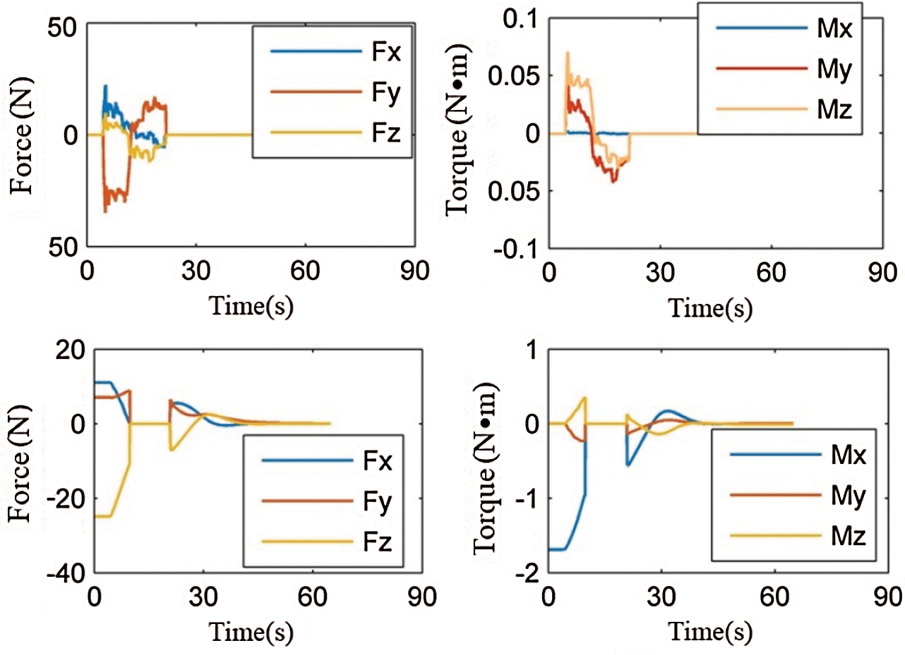
Figure 11: Human manipulation force (top) and visual force (bottom) under ISBHF
The manipulation by ISBHF is separated into three periods (the visual guidance forces (bottom) in Fig. 11). Firstly, the operator manipulates the robot and makes the feature points deviate from camera view intentionally, which is shown in Fig. 11 from 0 to 10 seconds. Then, the operator corrects the feature points’ image back into camera view field, which is shown in Fig. 11 from 10 to 20 seconds. The last period is mainly affected by the incorporated image servo forces and assisted with little human manipulation, which is shown in Fig. 11 from 20 to 30 seconds.
As shown in Fig. 12, the multi-colored curves and red curve represent the behavior of feature points and end-effector trajectory only under human manipulation, respectively, and the black ones record the guidance results under human manipulation with ISBHF control method.
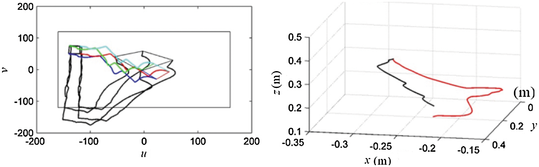
Figure 12: Comparison of feature points (left) and end-effector (right) trajectory between human manipulation and ISBHF
In term of the feature points (left) in Fig. 12, when incorporating human manipulation force with image servo based virtual force, we can use both to affect feature points’ position. Even though human manipulation may cause the target image to deviate from camera field view, the image servo based virtual force can guide the operator to calibrate the view back to the center view. When missing the visual sensory information, the operator can rely on the virtual force to correct robot camera view.
Comparing the red and black curves (the end-effector (right) in Fig. 12), it can be seen that the moving distance of robot end-effector is shorter by the ISBHF method, which means the robot can reach the target with less time and less posture adjustment. So the ISBHF control method can easily guide robot to track target and prevent image feature points deviating from camera view. It is favorable for robot to avoid the blind operation of human and the collision with other obstacles.
In this study, we proposed the ISBHF control method which is an image-based servo control method with virtual force, and we applied it into teleoperation. The stereo image vision method identified and extracted environment information, and then reconstructed a virtual scene to present visual guidance to the operator. A composite image Jacobian matrix was constructed based on the relationship between the image position change rate in the camera view and the end-effector position. The virtual force was created from the equation and composite image Jacobian matrix. Finally, the virtual force was fed back to the joysticks to restrict or guide the operation.
Experiments and comparisons between the ISBHF control method and PSBHF control method has verified the validity and reliability of the ISBHF control method. Human manipulation under the guidance of the virtual force can decrease the image servo error and end-effector position error. The ISBHF control method proves capable of preventing the image of the target object deviating out of the visual field of the camera. Therefore, the safety and stability of the manipulation can be improved.
Declarations: Ethical Approval and Consent to participate: Approved. Consent for publication: Approved. Availability of supporting data: The data used to support the findings of this study are available from the corresponding author upon request.
Funding Statement:This research was supported by the Key Research and Development Projects in Jilin Province (Grant No. 20200401130GX T. Ni) and National Natural Science Foundation of China (Grant No. 51575219 L.T. Huang). URLs: http://www.nsfc.gov.cn.
Conflicts of Interest: These are no potential competing interests in our paper. And all authors have seen the manuscript and approved to submit to your journal. We confirm that the content of the manuscript has not been published or submitted for publication elsewhere. The authors declare that they have no conflicts of interest to report regarding the present study.
1. G. Y. Liu, X. D. Geng, L. Z. Liu and Y. Wang. (2019). “Haptic based teleoperation with master-slave motion mapping and haptic rendering for space exploration,” Chinese Journal of Aeronautics, vol. 32, no. 3, pp. 723–736, . DOI 10.1016/j.cja.2018.07.009. [Google Scholar]
2. Y. S. Luo, K. Yang, Q. Tang, J. Zhang and B. Xiong. (2012). “A multi-criteria network-aware service composition algorithm in wireless environments,” Computer Communications, vol. 35, no. 15, pp. 1882–1892, . DOI 10.1016/j.comcom.2012.02.009. [Google Scholar]
3. M. Staniak and C. Zielinski. (2010). “Structures of visual servos,” Robotics and Autonomous Systems, vol. 58, no. 8, pp. 940–954, . DOI 10.1016/j.robot.2010.04.004. [Google Scholar]
4. J. M. Zhang, X. K. Jin, J. Sun, J. Wang and A. K. Sangaiah. (2020). “Spatial and semantic convolutional features for robust visual object tracking,” Multimedia Tools and Applications, vol. 79, no. 21, pp. 15095–15115, . DOI 10.1007/s11042-018-6562-8. [Google Scholar]
5. P. P. Kumar and L. Behera. (2010). “Visual servoing of redundant manipulator with Jacobian matrix estimation using self-organizing map,” Robotics and Autonomous Systems, vol. 58, no. 8, pp. 978–990, . DOI 10.1016/j.robot.2010.04.001. [Google Scholar]
6. L. Y. Xiang, X. B. Shen, J. H. Qin and W. Hao. (2019). “Discrete multi-graph hashing for large-scale visual search,” Neural Processing Letters, vol. 49, no. 3, pp. 1055–1069, . DOI 10.1007/s11063-018-9892-7. [Google Scholar]
7. F. Liu, S. Z. Mao and H. X. Wu. (2016). “On rough singular integrals related to homogeneous mappings,” Collectanea Mathematica, vol. 67, no. 1, pp. 113–132, . DOI 10.1007/s13348-015-0155-x. [Google Scholar]
8. T. Ni, H. Y. Zhang, P. Xu and H. Yamada. (2013). “Vision-based virtual force guidance for tele-robotic system,” Computers & Electrical Engineering, vol. 39, no. 7, pp. 2135–2144, . DOI 10.1016/j.compeleceng.2013.07.016. [Google Scholar]
9. T. Ni, X. P. Li, H. Y. Zhang, P. Xu and Z. Ma. (2013). “3-D vision-based kinesthesis teaching control strategy for telerobotics,” Transactions of the Chinese Society for Agricultural Machinery, vol. 44, no. 1, pp. 244–247. [Google Scholar]
10. Y. T. Chen, J. Wang, R. L. Xia, Q. Zhang and Z. H. Cao,. (2019). et al., “The visual object tracking algorithm research based on adaptive combination kernel,” Journal of Ambient Intelligence and Humanized Computing, vol. 10, no. 12, pp. 4855–4867, . DOI 10.1007/s12652-018-01171-4. [Google Scholar]
11. X. Y. Li, Q. L. Zhao, Y. X. Li and H. H. Dong. (2015). “Binary Bargmann symmetry constraint associated with 3 x 3 discrete matrix spectral problem,” Journal of Nonlinear Sciences and Applications, vol. 8, no. 5, pp. 496–506, . DOI 10.22436/jnsa.008.05.05. [Google Scholar]
12. J. A. Piepmeier, G. V. McMurray and H. Lipkin. (2014). “Uncalibrated dynamic visual servoing,” Robotics and Automation, IEEE Transactions on Robotics & Automation, vol. 20, no. 1, pp. 143–147, . DOI 10.1109/TRA.2003.820923. [Google Scholar]
13. J. Pomares, I. Perea, C. A. Jara, G. J. Garcia and F. Torres. (2013). “Dynamic visual servo control of a 4-axis joint tool to track image trajectories during machining complex shapes,” Robotics and Computer-Integrated Manufacturing, vol. 29, no. 4, pp. 261–270, . DOI 10.1016/j.rcim.2013.01.008. [Google Scholar]
14. Z. Cao, L. Yin, Y. Fu and T. Liu. (2013). “Predictive control for visual servo stabilization of nonholonomic mobile robots,” Acta Automatica Sinica, vol. 39, no. 8, pp. 1238–1245, . DOI 10.1016/S1874-1029(13)60047-6. [Google Scholar]
15. N. R. Gans, G. Hu, J. Shen, Y. Zhang and W. E. Dixon. (2012). “Adaptive visual servo control to simultaneously stabilize image and pose error,” Mechatronics, vol. 22, no. 4, pp. 410–422, . DOI 10.1016/j.mechatronics.2011.09.008. [Google Scholar]
16. X. Li, Y. Jiang, M. Chen and F. Li. (2018). “Research on iris image encryption based on deep learning,” EURASIP Journal on Image and Video Processing, vol. 2018, no. 1, pp. 126. [Google Scholar]
17. K. Khoshelham. (2011). “Accuracy analysis of Kinect depth data,” ISPRS — International Archives of the Photogrammetry, Remote Sensing and Spatial Information Sciences, vol. 3812, no. 5, pp. 133–138. [Google Scholar]
18. J. Y. Oh, H. S. Choi, S. H. Jung, H. S. Kim and H. Y. Shin. (2014). “Development of pallet recognition system using Kinect camera,” International Journal of Multimedia and Ubiquitous Engineering, vol. 9, no. 4, pp. 227–232, . DOI 10.14257/ijmue.2014.9.4.24. [Google Scholar]
19. P. J. Noonan. (2011). “The design and initial calibration of an optical tracking system using the Microsoft Kinect,” in 2011 IEEE Nuclear Science Sym.Conf. Record, Valencia, Spain, 24, pp. 441–445. [Google Scholar]
20. A. Ajouan, C. Fang, N. Tsagarakis and A. Bicchi. (2018). “Reduced-complexity representation of the human arm active endpoint stiffness for supervisory control of remote manipulation,” International Journal of Robotics Research, vol. 37, no. 1, pp. 155–167, . DOI 10.1177/0278364917744035. [Google Scholar]
21. L. R. Sanchez, H. A. Marin, H. E. R. Palacios, H. V. Rios-Figueroa and L. F. Marin-Urias. (2013). “A real-time 3d pose based visual servoing implementation for an autonomous mobile robot manipulator,” Procedia Technology, vol. 2013, no. 7, pp. 416–423, . DOI 10.1016/j.protcy.2013.04.052. [Google Scholar]
22. Y. Gui and G. Zeng. (2020). “Joint learning of visual and spatial features for edit propagation from a single image,” The Visual Computer, vol. 36, no. 3, pp. 469–482, . DOI 10.1007/s00371-019-01633-6. [Google Scholar]
 | This work is licensed under a Creative Commons Attribution 4.0 International License, which permits unrestricted use, distribution, and reproduction in any medium, provided the original work is properly cited. |