
 Submit a Paper
 Propose a Special lssue
 Open Access
ARTICLE
Numerical Investigation of the Influence of a Magnetic Field on the Laminar Flow of a Yield-Stress Nanofluid over a Backward Facing Step
1 Mechanical Manufacturing Technology Research Laboratory (LaRTFM), National Polytechnic School of Oran Maurice Audin, El mnaouar, Bp 1523, Es-senia, Oran, 31000, Algeria
2 Department of Industrial Engineering DIN, Alma Mater Studiorum-University of Bologna, Viale Risorgimento 2, Bologna, 40136, Italy
3 Laboratory of Maritime Sciences and Engineering, LSIM Faculty of Mechanical Engineering, University of Science and Technology of Oran, Mohamed Boudiaf, El Mnaouer, Oran, 31000, Algeria
4 Mechanics, Modeling and Experimentation Laboratory L2ME, Faculty of Sciences and Technology, Bechar University, Bechar, 08000, Algeria
* Corresponding Authors: Karim Amrani. Email: ; Eugenia Rossi di Schio. Email:
(This article belongs to the Special Issue: Heat Transfer Enhancement for Energy Applications)
Frontiers in Heat and Mass Transfer 2025, 23(1), 185-206. https://doi.org/10.32604/fhmt.2025.059833
Received 17 October 2024; Accepted 25 December 2024; Issue published 26 February 2025
 View Full Text
 Download PDF
Abstract
The present study focuses on the flow of a yield-stress (Bingham) nanofluid, consisting of suspended Fe3O4 nanoparticles, subjected to a magnetic field in a backward-facing step duct (BFS) configuration. The duct is equipped with a cylindrical obstacle, where the lower wall is kept at a constant temperature. The yield-stress nanofluid enters this duct at a cold temperature with fully developed velocity. The aim of the present investigation is to explore the influence of flow velocity (Re = 10 to 200), nanoparticle concentration ( = 0 to 0.1), magnetic field intensity (Ha = 0 to 100), and its inclination angle (γ = 0 to 90) and nanofluid yield stress (Bn = 0 to 20) on the thermal and hydrodynamic efficiency inside the backward-facing step. The numerical results have been obtained by resolving the momentum and energy balance equations using the Galerkin finite element method. The obtained results have indicated that an increase in Reynolds number and nanoparticle volume fraction enhances heat transfer. In contrast, a significant reduction is observed with an increase in Hartmann and Bingham numbers, resulting in quasi-immobilization of the fluid under the magnetic influence and radical solidification of this type of fluid, accompanied by the suppression of the vortex zone downstream of the cylindrical obstacle. This study sheds light on the complexity of this magnetically influenced fluid, with potential implications in various engineering and materials science fields.Keywords
In the modern industrial context, the efficiency of cooling plays an important role in the performance and durability of equipment. Several industrial applications involve the cooling of components subjected to high temperatures, whether in power generation systems, chemical processes, or electronic cooling technologies. Conventional cooling techniques typically rely on traditional cooling fluids like water or specific oils [1–3]. However, research and development have recently turned toward the use of nanofluids [4], which are suspensions of nanoparticles in a base fluid, to enhance heat transfer properties. These nanofluids hold considerable potential for optimizing cooling in various industrial applications [5,6]. Furthermore, in an increasingly energy-efficient world, the introduction of magnetic fields into these cooling systems presents a promising new dimension [7–9].
Rheology in the presence of nanofluids pertains to the study of how these nanoparticle suspensions behave under mechanical stress and temperature changes. Understanding the rheological properties of nanofluids is important in optimizing their thermal performance in applications like electronic cooling and energy generation, as they can significantly influence heat transfer due to their affected thermal conductivity [10]. Indeed, nanofluid rheology influences factors like stability, dispersion, and response to mechanical stress, impacting fluid behavior in applications involving pumping, flow, and thermal convection [11,12].
Backward-facing step (BFS) ducts are of great importance in heat transfer due to their ability to enhance fluid mixing and promote turbulence. This phenomenon is important for improving heat transfer in various fields, including industrial cooling systems, heat exchangers, and combustion systems. BFSs thus contribute to increased energy efficiency, reduced cooling costs, and optimized heating processes, making them key elements in the thermal management of many industrial applications [13–15].
Given the significance of heat transfer in the presence of nanofluids within backward-facing step (BFS) ducts, several studies aimed at enhancing and contributing to theoretical knowledge have been conducted in the scientific literature. Hussanan et al. [16] performed a study on heat transfer enhancement of viscoplastic non-Newtonian fluid over a stretching sheet using sodium alginate-based hybrid nanofluids. Selimefendigil et al. [17] proposed a new method for controlling the Thermal Transfer of a laminar flow through a double backward-facing step under the effect of a magnetic field by introducing highly conductive nanoparticles into the base fluid in order to show the effect of different parameters such as Reynolds number, distance between the steps and the magnetic field orientation on the hydrodynamic performance of the flow. Aly et al. [18] studied the thermo-solutal convection in a finned cavity of a nanofluid. The results show that the motion of the nanofluid particles stops due to the increase of the Hartmann number and the strength of magnetism. Mokaddes et al. [19] numerically studied a mixed convection of a nanofluid through a shed with rotating cylinders under the effect of a heat source in the presence of a magnetic field to show the effect of the rotation speed of the cylinders and the magnetic field on the flow and the Heat Transfer. Ghachem et al. [20] studied the forced convection of a hybrid nanofluid flow on a three dimensional backward-facing step to analyse the effects of a corrugated porous layer and the effects of magnetic field on Nusselt number and pressure drop. Klazly et al. [21] numerically investigated the heat transfer of Newtonian and non-Newtonian fluids including nanofluids over backward-facing step channel to show the effects of thermo-physical properties of nanoparticles on the heat transfer enhancement.
Due to the potential for a complex rheology of nanofluids, researchers have also presented corresponding literature. Indeed, a majority of water-based suspensions can exhibit a shear thinning behavior (pseudoplastic). However, by implementing non-Newtonian base fluids outside of pseudoplasticity behavior, the resulting suspension evidently exhibits such behavior. Akrama et al. [22] studied a peristaltic flow of a Bingham fluid on the channel with different wave forms to the show the effect of heat and mass transfer in the presence of inclined magnetic field. Javadpour et al. [23] experimentally investigated the enhancement of heat transfer in the laminar forced convection of non-Newtonian nanofluid through a tube. Alizadeh et al. [24] studied the effect of nanofluid blowing on the forced convection heat transfer through a sudden expansion for turbulent flow of three different fluids. Muhyaddin et al. [25] numerically investigated the effect of blade angles of a helical channel on the thermal-hydraulic efficiency of a two-phase non-Newtonian nanofluid flow. They showed that for higher Reynolds numbers the heat transfer increases and the Nusselt number is higher. Kherroubi et al. [26] numerically studied a laminar mixed convection flow of Bingham fluid over ventilated cavities using uniform magnetic field to examine the effect of different parameters such as Reynolds number, nanoparticles volume fraction and the magnetic inclination angle on the heat exchange and the pressure drop Lahlou et al. [27] proposed an approach based on Buongiorno’s non-homogeneous model for modeling the hybrid nanoparticle migration on viscoplastic fluid flow in heated cavity to study the temperature dependence. Kazemi et al. [28] investigated the enhancement heat transfer of no-Newtonian magneto hydro dynamics (MHD) fluid flow in the presence of angular magnetic field on the channel. Borrelli et al. [29] made an investigation on the Bingham fluid flow through vertical channel by introducing external magnetic field. Vishalakshi et al. [30] in their work, studied the effect of an inclined magnetic field on MHD fluid flow over a porous sheet. Dawar et al. [31] report the effect of magnetic field and thermal radiation on MHD flow of non-Newtonian nanofluid over a flat plate. Sohail et al. investigate the Buongiorno model with the Carreau constitutive model in a Jeffery-Hamel flow of Newtonian fluid over two plans wall [32]. In [33], Boujelbene et al. studied the effect of nanofluid flow configuration on heat transfer and entropy degradation over an inclined channel, focusing on the stimulus of Lorentz force.
Based on the analysis of previous research in the literature on nanofluid flow within backward-facing step (BFS) configurations, it becomes evident that this field has gained significant importance in recent years. However, it is noteworthy that no previous work has explored the yield-stress behavior of nanofluids, which can lead to solidification in the presence of a magnetic field. Hence, to bridge the gap in the literature, the objective of this paper is to provide a theoretical investigation into the hydrodynamic and thermal behavior, focusing on heat transfer efficiency, of a yield-stress nanofluid comprising conductive iron oxide (Fe3O4) in a backward-facing step subjected to a magnetic field. The influence of key parameters is highlighted on the mentioned behaviors, including nanofluid velocity, magnetic field intensity and angle, and the yield stress of this particular nanofluid. This study also offers a profound understanding of the thermal phenomenon, particularly in the context of the complexity near electrical equipment.
Let us consider an enlarged flow duct configuration, a backward-facing step (BFS), featuring a narrowed and an enlarged section of diameter H and 2H, respectively. Downstream of the enlargement zone, a cylindrical obstacle of a diameter H is introduced with a distance H from the enlarged part. The lower wall of the enlarged section of the BFS is maintained at a constant hot temperature (Th), highlighting the effect of heat dissipation from adjacent electronic equipment, which also generates a uniform magnetic field (B) inclined with an angle γ with respect to the horizontal line. However, the other walls of this duct are considered adiabatic, as shown in Fig. 1.
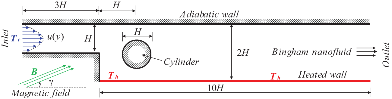
Figure 1: 2D-geometric configuration of the studied backward-facing step
Inside this duct, a nanofluid containing suspended Fe3O4 nanoparticles is flowing in a two-dimensional (2D) steady-state regime; therefore, a velocity profile u(y) = 4 u0 (y/H)(1 − y/H) of maximum u0 is introduced in the duct inlet. The nanofluid’s initial temperature is cold (Tc), and it exhibits a non-Newtonian Bingham yield stress rheology, meaning that it starts flowing only when the applied stress exceeds this yield (τ0).
On the other hand, the flow of the nanofluid is influenced by convection, driven by the effect of the hot wall in the enlarged section. Due to the ferromagnetic nature of the Fe3O4 nanoparticles in the nanofluid, it is also electrically conductive. Hence, the nanofluid flow can be magnetically influenced due to the magnetic field generated by the electronic equipment, see Fig. 1.
3.1 Dimensional Governing Equations
The Bingham nanofluid two-dimensional flow inside the BFS duct is considered laminar, steady, incompressible and magnetohydrodynamic (MHD). This flow is governed by the balances of mass, momentum, and energy. The flow theatrical description is made assuming that the thermophysical proprieties of the nanofluid namely, density (ρ), thermal conductivity (k), thermal capacity (Cp) and electrical conductivity (σ) are constants. However, due to the yield stress rheology nature of the nanofluid, the viscosity (μ) varies as a function of the shear rate (γ). Moreover, in a Cartesian referential (O, x, y), while neglecting nanoparticle interaction and buoyancy forces, if (u, v), p, τ and T presents respectively velocity components, pressure, shear stress and temperature, the governing equations for this magnetohydrodynamic flow are expressed in dimensional form as follows:
Mass balance
Momentum balance
Energy balance
The indices p, f and nf denote respectively the proprieties of nanoparticles, base fluid and nanofluid. The shear stress, denoted as τij, represents the shearing force acting along the i and j directions, which can be defined as ij: = xx, xy or yy. The shear stress is hence defined as a function of the yield stress τy as follows:
with ux = u, uy = v and xx = x, xy = y. If τ > τy, the apparent viscosity of the nanofluid is provided according to Bingham and Brinkmann [34] laws as follows:
In Eq. (6), μp presents the plastic viscosity of the Bingham nanofluid.
The density (ρnf), thermal conductivity (knf), heat capacity (Cpnf), and electrical conductivity (σnf) of the nanofluid (nf) are functions of the nanoparticle volume fraction (φ), the properties of the Bingham base fluid (f), and the properties of the nanoparticles (p). They are given by the following expressions [35]:
3.2 Dimensionless Governing Equations
The present study aims to highlighting the thermal and hydrodynamic behavior of a nanofluid with a yield stress-based fluid by comparing it with different yield intensities, including the Newtonian case (absence yield stress). Therefore, dimensionless analysis can serve for this purpose. Hence, all governing equations Eqs. (1)–(4) are transformed into a set of dimensionless equations Eqs. (12)–(15) based on the dimensionless quantities presented in Eq. (11).
Mass balance
Momentum balance
Energy balance
The dimensionless equations Eqs. (12)–(15) show certain dimensionless numbers, namely the Reynolds (Re), Hartmann (Ha) and Prandtl numbers (Pr). They are respectively given by:
On the other hand, μ presents a dimensionless apparent viscosity of the Bingham nanofluid. It is defined as:
The Bingham number (Bn) represents the ratio between yield stress and viscous stress in a fluid. Moreover, it serves to characterize the stress intensity within the fluid. As the Bingham number increases, it indicates a corresponding increase in the yield stress. It is given by:
The propriety α represents the thermal diffusivity of the Bingham nanofluid. It is generally defined for base fluid or nanofluid by:
The dimensionless equations Eqs. (12)–(15) have been solved to determine the numerical solution of the studied problem, see Fig. 1. To achieve this, a set of boundary conditions has been incorporated into the governing equation system as follows:
At the nanofluid inlet:
At the nanofluid outlet:
At the lower wall of the enlarged part of the duct:
At the rest of walls:
where N is the normal coordinate of the indicated wall.
The Nusselt number (Nu) is a critical parameter in convective heat transfer studies, providing a dimensionless measure of heat transfer rate (h). In the present investigation, this number is computed at the hot wall to assess its cooling reliability. Its local value is given by:
where hnf is the convective coefficient, namely:
Hence, by substituting Eq. (25) into Eq. (24), we obtain:
In dimensionless terms:
The average Nusselt number provides a full view of heat transfer within the duct. Its average value at the hot wall is given by [36]:
The system of equations Eqs. (12)–(15), accompanied by boundary conditions Eqs. (20)–(23), is numerically solved using the Galerkin finite element method. This method involves discretizing the domain into finite elements, where each element is characterized by a shape function. These shape functions are chosen to best approximate the behavior of the solution within each element. The Galerkin method then minimizes energy functional, leading to a discrete system of algebraic equations that can be solved numerically.
The mesh used to discretize the governing equations in the BFS adopts a predominantly triangular structure, with the exception of the walls of the BFS where a rectangular boundary layer is introduced. Additionally, the mesh is refined significantly in the vicinity of the cylindrical obstacle.
This approach allows for a more accurate representation of flow behavior, paying particular attention to critical zones such as the walls of the BFS and the proximity of the cylindrical obstacle. The choice of a rectangular boundary layer at the walls can enhance the capturing of physical phenomena near these surfaces, while mesh refinement near the obstacle ensures fine resolution of flow features in that specific region [37,38]. Fig. 2 depicts the described mesh, where Fig. 2a presents the actual mesh, and Fig. 2b highlights a coarse mesh solely for the purpose of visualizing the shape of the mesh elements.
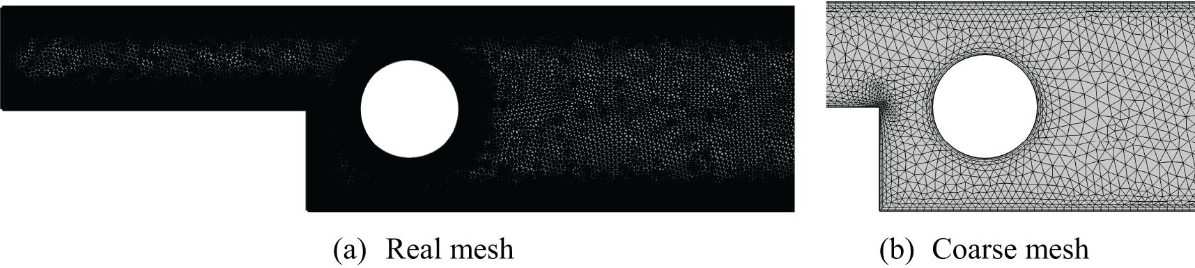
Figure 2: Computationnel Domain (BFS) mesh
To confirm the independence of the present numerical results from the chosen mesh grid, a systematic progressive test of the element number has been conducted. The testing procedure involves gradually refining the mesh by increasing the element number from M1 to M5 (5 meshes) and monitoring the evolution of the average Nusselt number. Once the mesh is reached beyond which the Nusselt number remains unchanged, it is adopted as the optimal mesh in terms of accuracy and computation time. Table 1 presents the evolution of the Nusselt number as a function of the mesh for the test, under critical and global conditions where Re = 200, Ha = 100, Bn = 20, Pr = 6.2, and
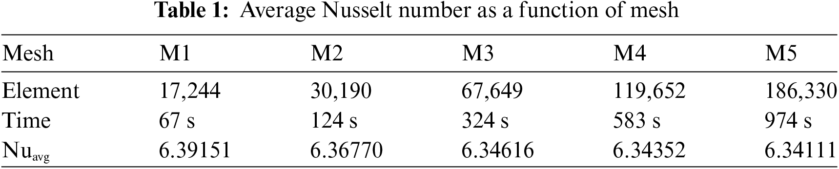
It is noteworthy that the results are deemed achieved when the absolute error between the new dependent variables and the old ones, in terms of iterations, falls below 10−6. Additionally, it is worth noting that the numerical computations were performed on a Windows 11 desktop computer with an i7 CPU, 12 GB RAM, and a frequency of 4 GHz.
In order to validate the computational code, a comparison between the results obtained from the present code and those from the literature, specifically the work by Hussain et al. [8], has been conducted. By adopting the same simulation conditions, we have plotted certain local characteristics, including isotherms and streamlines, for Re = 100, Ha = 25, Pr = 6.2, and
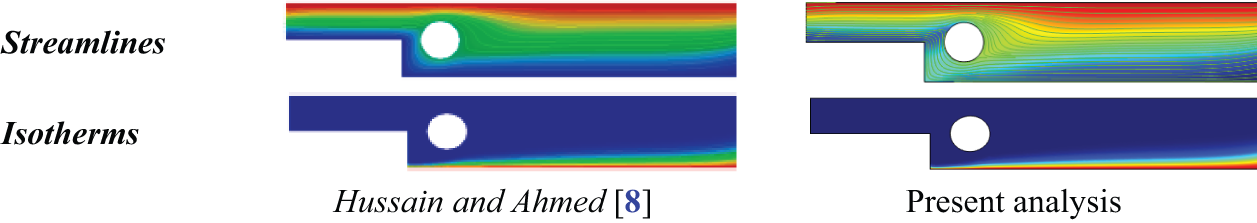
Figure 3: Streamlines and isotherms of the present study compared with Hussain et al. [8] at Re = 100, Ha = 25, γ = 30° and φ = 0.05
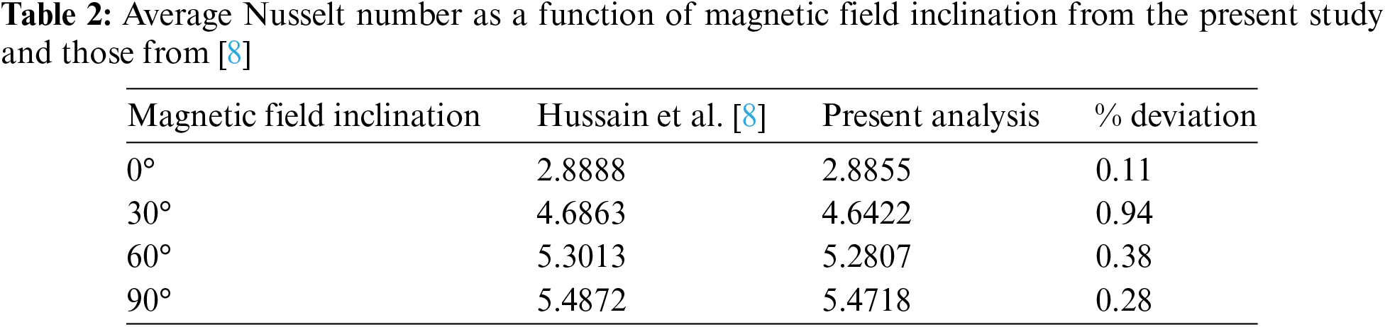
The comparison of different numerical results, both local and global presented respectively in Fig. 3 and Table 2, demonstrated very good agreement, thus validating the present computational code. Moreover, the results showed in Table 2 exhibit an outstanding agreement with the literature, with the deviation of the Nusselt number not exceeding 0.3%. This minimal variation confirms the reliability of the present computational code in reproducing comparative results. It is worth noting that this comparison has been extended across various simulation conditions, further consolidating the robustness of our approach.
In this section, the numerical results of our research obtained through numerical simulation are presented. The aim of this study is to highlight the influence of various parameters such as the intensity (Ha = 0 to 100) and angle of the magnetic field (γ = 0° to 90°), flow velocity (Re = 10 to 200), concentration of alumina nanoparticles (φ = 0 to 0.1), and the yield stress of the Bingham fluid (Bn = 0 to 20) on the hydrodynamic and thermal behavior of the studied flow inside the BFS. The results, with Prandtl number (Pr) fixed at 6.2, are depicted in the form of streamlines and isotherms. Furthermore, to analyze thermal efficiency, local and average Nusselt numbers are presented through graphs.
Computational fluid dynamics studies primarily focus on understanding the influence of inertia, i.e., the flow velocity, on hydrodynamic and thermal parameters. To achieve this, the Reynolds number serves as a dimensionless parameter highlighting the impact of the inlet velocity of the nanofluid into the BFS. In other words, as the Reynolds number increases, the velocity at the inlet also increases. In this subsection the other parameters namely, Hartmann number, Bingham number, nanoparticles concentration has respectively been set at Ha = 0, Bn = 0 and φ = 0.04.
Fig. 4 illustrates the stream function distribution, streamlines, and temperature distribution inside the BFS for different Reynolds numbers, namely 10, 50, 100, and 200. As the Reynolds number increases, a recirculation loop zone (vortex) develops downstream of the cylindrical obstacle, particularly at higher Reynolds numbers (Re = 200). At this value, a weak additional vortex forms immediately downstream of the abrupt expansion plane, effectively creating a dead zone. The development of these vortices is attributed to singular pressure drops caused by the cylinder and the expansion, leading to a reversal in the flow direction. In reality, the cylinder installed downstream of the expansion zone aims to disrupt the vortex forming immediately after this expansion area, which intensifies as the inlet velocity to duct (BFS) increases. Nevertheless, at higher Reynolds numbers, the vortex induced by the expansion forms due to the significant pressure drop in this region. It should be noted, that the flow intensity, represented by the maximum stream function, increases as the Reynolds number increases, also indicating a rise in the mass flow rate through the BFS.
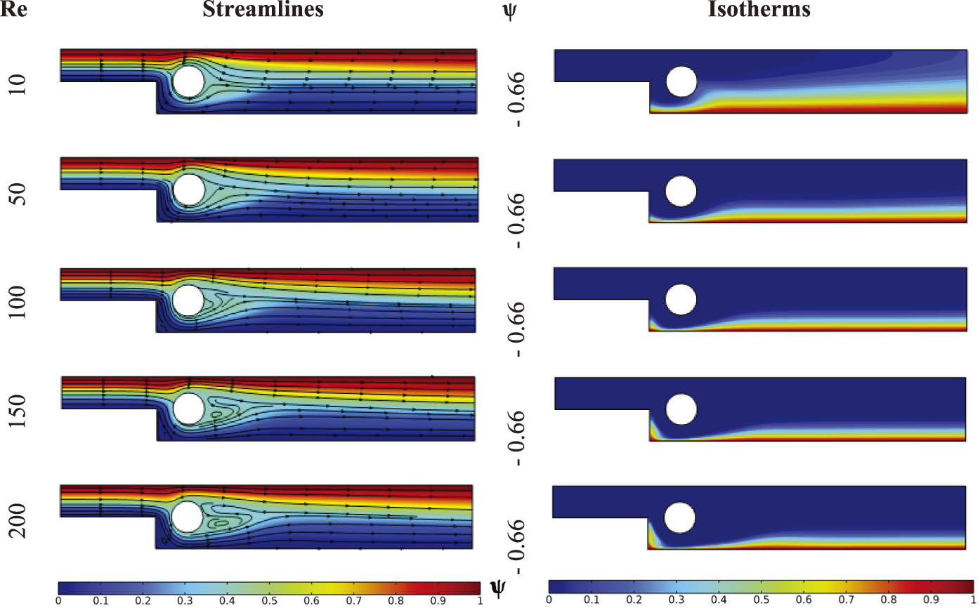
Figure 4: Streamlines and isotherms for various Reynolds number at Ha = 0, γ = 0, Bn = 0 and φ = 0.04
As for the temperature distribution, the thickness of the thermal boundary layer along the hot wall downstream of the obstacle significantly decreases as the Reynolds number increases from 10 to 200. Indeed, pronounced dissipation of thermal flux has been observed during low-velocity laminar flow (Re = 10), indicating low thermal convection and suggesting that thermal transfer primarily occurs through predominant conduction. Moreover, at moderate flow velocities, the thickness of thermal boundary layer is decreased by the effect of flow stream due to intensified forced convection and the due to dominance of fluidic kinetics over molecular agitation between fluid particles.
Exceptionally, in the region within the expansion plane upstream of the obstacle, increasing the Reynolds number results in a relative increase in the thickness of the thermal boundary layer. This is attributed to the formation of the dead zone, which becomes weaker or stagnant with the increasing Reynolds number, leading hence to a decrease in the convection rate and, consequently, an increase in conduction.
For a more in-depth analysis of the thermal behavior, a key element in the present investigation, it is necessary to conduct an analysis based on identifying the heat transfer rate through the local Nusselt number along the hot wall. Fig. 5 presents the distribution of this number for different Reynolds numbers. Consistent with the temperature contours (Fig. 4), the local Nusselt number strengthens the previously made observations. It is noteworthy, according to the local Nusselt number graph, that heat transfer is enhanced as the Reynolds number increases, especially just below the obstacle where it reaches its maximum in this area before decreasing towards the BFS outlet, regardless of the Reynolds number. Indeed, the cross-sectional area in this zone decreases, and as mass flow rate is conserved (continuity equation), the velocity increases below the obstacle, thus intensifying forced convection and leading to a pronounced increase in the heat transfer rate. On the other hand, the decrease in the local Nusselt number upstream of the obstacle against the flow is consistent with the formation of the additional vortex (dead zone), see Fig. 4, also resulting in a relative decrease even at very high Reynolds numbers.
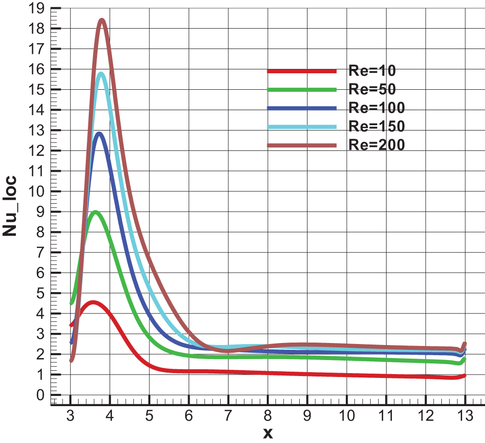
Figure 5: Local Nusselt number along the heated wall for different Reynolds Number at Ha = 0, γ = 0, Bn = 0 and φ = 0.04
5.2 Magnetic Field Intensity Effect
Flows subject to magnetic fields, with uniform intensity, constitute an integral part of hydrodynamic performance analyses in such research areas. As nanofluids contain particles that can be electrically conductive, they can be influenced by a magnetic flux density that can strongly affect the trajectories of their elements, especially in the case of ferromagnetic nanofluids. As described in the geometric presentation section, namely Section 2, the flow of the nanofluid is subjected to a uniform magnetic field B, making the flow to be magnetohydrodynamic (MHD). Thus, the Hartmann number serves as a dimensionless parameter describing the magnetic flux density at various inclination angles. In this subsection, it should be noted that the values of the Reynolds number, Bingham number, and volume fraction of nanoparticles have been fixed at Re = 100, Bn = 0, and φ = 0.04, respectively. However, for different values of the Hartmann number the magnetic field is considered horizontal where the inclination angle has been set at γ = 0°.
Fig. 6 illustrates the stream function distribution as well as streamlines, and temperature distribution inside the BFS for different Hartmann numbers. The most noticeable and critical observation, especially for a horizontal magnetic field, pertains to the hydrodynamic behavior of the nanofluid. Indeed, the introduction of a magnetic field, and its intensification through an increase in the Hartmann number, results in a radical change in the flow structure within the BFS. The configuration of streamlines confirms an increasing disturbance based on the magnetic flux density. This disturbance generates a non-integral flow downstream of the obstacle, precisely in the middle of the BFS, characterized by zigzagging fluidic trajectories with diminishing amplitude away from the obstacle. This zigzag becomes more pronounced with the increase in the Hartmann number, influencing the flow with a normal force, known as the Lorentz force. Consequently, the flow intensity decreases significantly due to this magnetic disturbance. This phenomenon can lead to an increased vibration, especially as the magnetic flux density becomes more significant, potentially degrading the long-term lifetime of the solid walls.
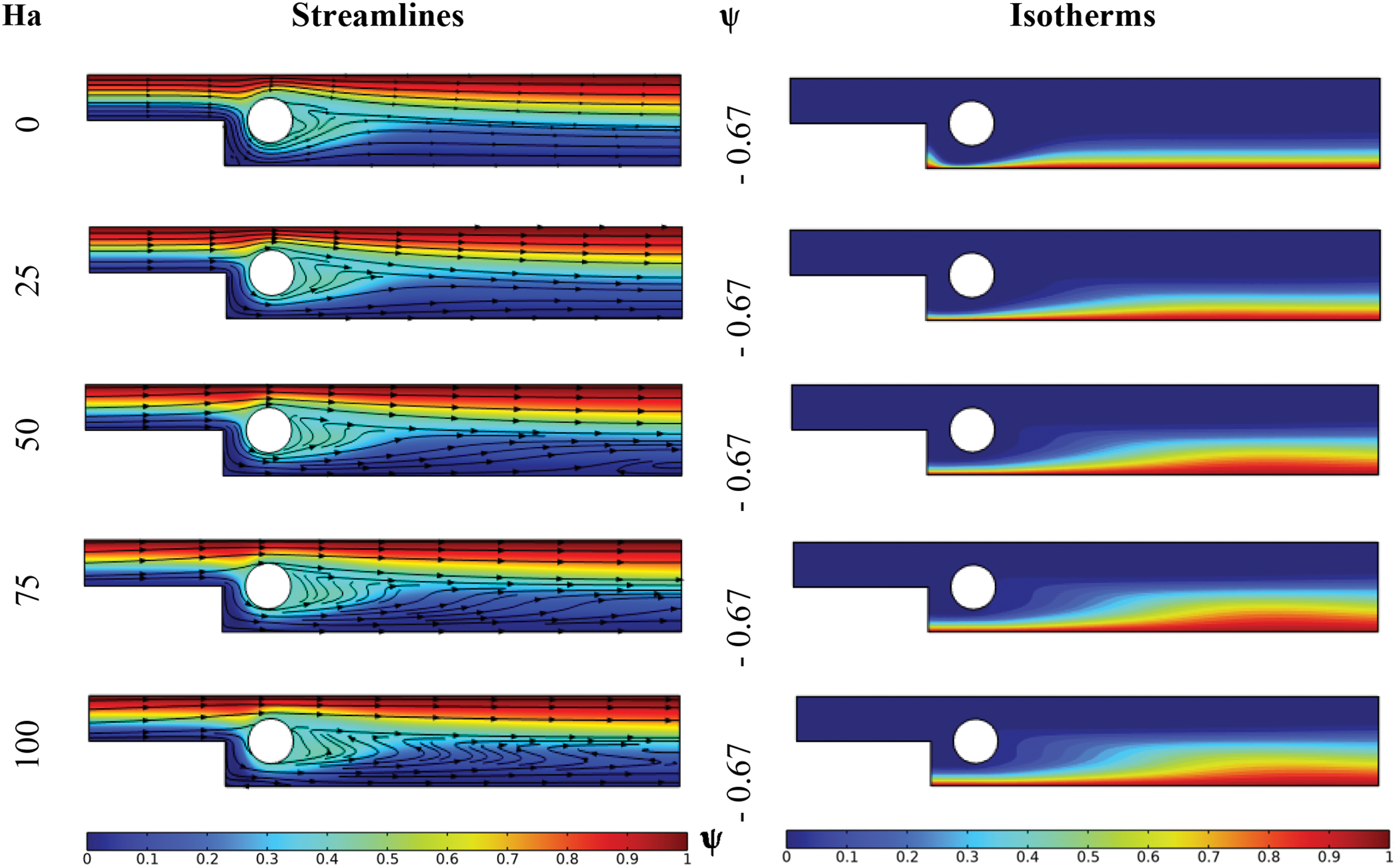
Figure 6: Streamlines and isotherms for various Hartmann number at Re = 100, γ = 0, Bn = 0 and φ = 0.04
Moreover, as the flow intensity has been substantially reduced, the local flow velocity decreases significantly, thus reducing the intensity of convection. Hence, according to the thermal state, the thickness of the thermal boundary layer increases significantly with the increase in the Hartmann number along the entire hot wall of the BFS, including the region near the expansion plane. Examining the isotherm configuration reveals that they are quasi-similar to the streamlines, where the zigzag disturbance also appears in the temperature contours. Consequently, the thermal state is strongly dependent on the magnetohydrodynamic state.
Fig. 7 presents the distribution of the local Nusselt number along the hot wall of the BFS for different Hartmann numbers. As expected, the Nusselt number decreases significantly regardless of the Hartmann number. Hence, the heat transfer rate decreases as an increasingly dense horizontal magnetic field is introduced. Furthermore, examining the configuration of the Nusselt number graphs reveals that all curves representing this number along the hot wall almost intersect at a single point, located at a distance of 2H from the center of the cylindrical obstacle.
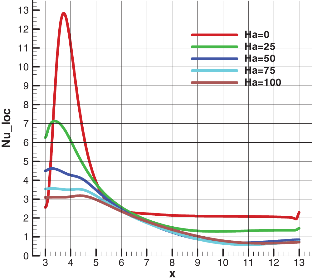
Figure 7: Local Nusselt number along the heated wall for different Hartmann Number at Re = 100, Bn = 0 and φ = 0.04
In fact, the intersection of all curves of the local Nusselt number at a single point signifies that the convection rate is the same at this point. Thus, the thickness of the thermal boundary layer must be the same regardless of the Hartmann number. This suggests that the fluid velocity at this point is constant. This observation is linked to the disturbance in fluid trajectories induced by the influence of the Lorentz force.
5.3 Magnetic Field Angle Effect
In this section, we analyze the influence of the inclination angle of the uniform magnetic field on the behavior of the nanofluid within the BFS. This specific part of the investigation is an important aspect of analyzing the effects of magnetic fields, providing insights into the influence of direction on flow within ducts more generally.
The angle of the magnetic field has been varied between 0° and 90° to cover possible cases of magnetic field direction with an average intensity corresponding to Ha = 25. At this situation, the Reynolds number, Bingham number, and volume fraction of nanoparticles have been fixed at Re = 100, Bn = 0, and φ = 0.04, respectively.
Fig. 8 presents the distribution of the stream function, the pattern of streamlines, and temperature contours within the BFS for different angles of the magnetic field, namely 0°, 30°, 60°, and 90°. At the 0° angle, corresponding to the application of a horizontal magnetic field, a slight disturbance of the streamlines has been observed immediately downstream of the cylindrical obstacle. However, by tilting the magnetic field (with the same flux density) at 30° and 60° angles, the streamlines become arranged and horizontally parallel. Except for the BFS outlet, where these streamlines incline upstream immediately before this outlet, in accordance with the magnetic field inclination angle. Indeed, this effect is due to the influence of the Lorentz force affecting the flow normally to the direction of the magnetic field. This results in the creation of a pressure drop immediately upstream of the outlet, redirecting the flow upwards. At the 90° angle, the Lorentz force is parallel to the flow and in its direction, positively influencing the flow and consequently its mobility and fluidity. Going from the 0° to 90° angle, the inclination angle positively affects the flow by increasing its intensity. Indeed, given the perpendicularity of the Lorentz force to the magnetic field, a horizontal field is perpendicular to the streamlines (direction of flow), which results in a significant flow blockage, in contrast to the 90° angle. It is noteworthy that immediately downstream of the expansion plan below, the inclination of the magnetic field manages to break up the dead zones, further enhancing mobility in these critical zones.
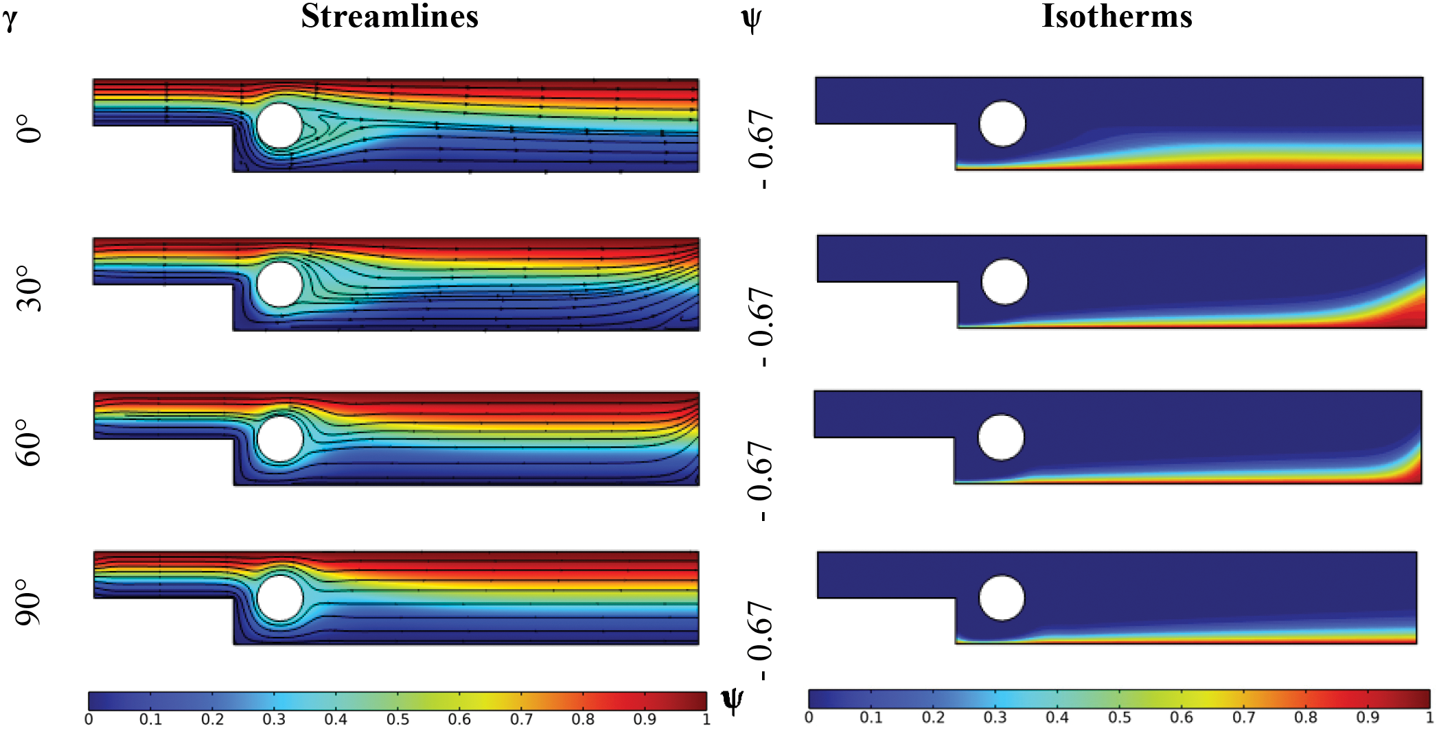
Figure 8: Streamlines and isotherms for various magnetic field angle inclination at Re = 100, Ha = 25, Bn = 0 and φ = 0.04
Regarding the temperature distribution for different inclination angles, the pattern of the isotherms is almost similar to that of the streamlines. Indeed, the inclination of the isotherms is observed immediately upstream of the outlet in accordance with the inclination of the streamlines already noted in this zone. Moreover, as this angle increases, the thickness of the boundary layer along the hot wall decreases significantly from angle 0° to 90° in most of the heated wall length, except for the outlet. Exceptionally, for angles 30° and 60°, an enlargement of the boundary layer is observed in the zone just upstream of the BFS outlet. Indeed, the pressure drop in reaction to the Lorentz force in this zone leads to a decrease in kinetic energy in this area, with even the possibility of creating a dead zone if a higher magnetic flux density had been applied. This results in the predominance of the conduction mode of heat transfer. Thus, in a cooling scenario, this zone would be poorly cooled by the fluid flow.
The local Nusselt number along the hot wall, associated with different inclination angles, provides a clearer visualization of the convective thermal behavior within the BFS. Indeed, according to Fig. 9, an increase in the inclination angle of the magnetic field essentially leads to an increase in the convective heat transfer rate, especially in the intermediate zone between the downstream of the obstacle and the BFS outlet, with exceptional enhancement at the 90° angle. This aligns with the reduction in the thickness of the thermal boundary layer in this zone. Below the obstacle, higher rates of heat transfer were noted for angles of 30° and 60° due to the moderate and optimal elimination of the dead zone at angles near 30° and 60°.
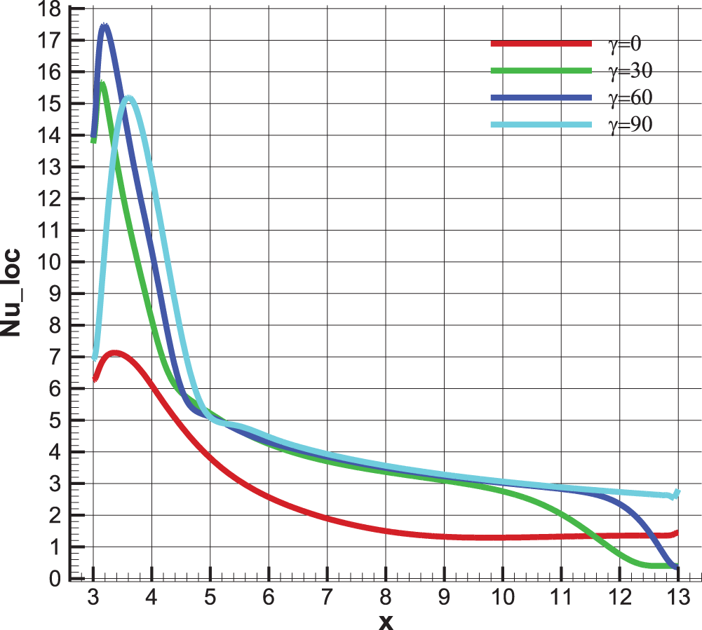
Figure 9: Local Nusselt number along the heated wall for different magnetic field angles, for Ha = 25, Re = 100, Bn = 0 and φ = 0.04
5.4 Nanoparticle Concentration Effect
Nanofluids are liquid substances generally used to enhance the heat transfer rate due to their high conductivity compared to the base fluid. In this section, we investigate the influence of adding ferromagnetic Fe3O4 nanoparticles at different volume fractions to the base fluid, including the base fluid itself, on the thermal and hydrodynamic structures of the BFS. To achieve this, the Reynolds, Hartmann, and Bingham numbers are kept constant at the values Re = 100, Ha = 0, Bn = 0.
Fig. 10 presents the distribution of the stream function, the pattern of streamlines, and the temperature distribution within the BFS for different volume fractions of nanoparticles. It is clearly observable that the thermal and hydrodynamic profiles are entirely similar, where it is challenging to discern the difference between them in terms of shapes and intensity.
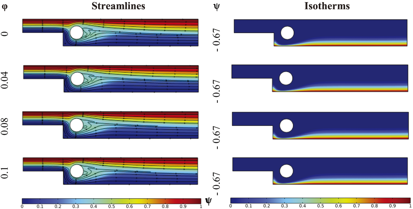
Figure 10: Streamlines and isotherms for various nanoparticle concentrations at Re = 100, γ = 0, Bn = 0
However, some difference can be noted in terms of streamlines in the immediate vicinity of the obstacle, where the flow disturbance changes relatively under the implemented conditions. This effect is actually due to three main causes: the low concentrations of the nanoparticles used, the small diameters of the nanoparticles, and forced convection. Indeed, it is challenging to perceive the influence on the hydrodynamic profile of forced convection flows due to the absence of buoyancy forces that generate flow streams due to the difference in density induced by temperature effects. As the addition of nanoparticles influences the temperature value, buoyancy forces increasingly drive the flow by generating additive streams that might appear in the structure of streamlines. However, due to the predominance of inertia forces (fluid velocity), the effect of natural convection is weak and so that negligible. Thus, it is hard to notice changes in terms of hydrodynamic behavior [11].
Local Nusselt number along the hot wall, presented in Fig. 11, shows that the addition of nanoparticles increases the heat transfer rate practically with the same intensity at every point along the wall, unlike the other cases discussed earlier. This observation suggests that the influence of nanoparticles on heat transfer is uniform along the hot wall, regardless of the position in the BFS. This uniformity can be attributed to the predominant forced convection and the weak influence of natural convection under the considered conditions. The nanoparticles, by increasing the thermal conductivity of the fluid, globally enhance heat transfer along the hot wall. However, it is essential to note that this conclusion is specific to the study conditions and the properties of the nanoparticles used.
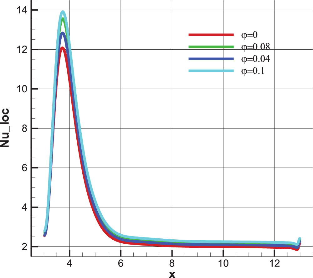
Figure 11: Local Nusselt number along the heated wall for different nanoparticle concentrations φ at Ha = 0, Re = 100, γ = 0, Bn = 0
In this sub-section, we analyze the impact of the yield stress of the nanofluid studied on hydrodynamic and thermal behaviors within the BFS. As described in geometry presentation, the non-Newtonian Bingham nanofluid involves suspending Fe3O4 nanoparticles in a base fluid with a yield stress, following the Bingham model. This analysis focuses on the effect of the yield stress on the mentioned behaviors, and the exploration of this effect is carried out through the definition of the Bingham number. Indeed, increasing this number corresponds to an increase in the yield stress, which will be helpful in our dimensionless analysis. It should be noted that, in this analysis, the Reynolds and Hartmann numbers, as well as the nanoparticle concentration, are held constant at Re = 100, Ha = 0, and phi = 0.04, respectively.
Fig. 12 presents velocity contours, streamline patterns, and isotherms within the BFS for different Bingham numbers. It is clear from this figure that increasing the Bingham number generally reduces flow intensity and eliminates the vortex formed downstream of the cylindrical obstacle. Thus, a preliminary analysis of hydrodynamic profiles suggests that increasing the Bingham number, or the yield stress, decreases flow. However, the thermal analysis shows a clear reduction in the thickness of the thermal boundary layer, implying an inevitable increase in velocity. This may appear contradictory to the overall observation. Therefore, it is imperative to consider additional results highlighting details on velocity profiles in the immediate vicinity of the hot wall to better understand the behavior of the boundary layer, especially when using Bingham fluids.
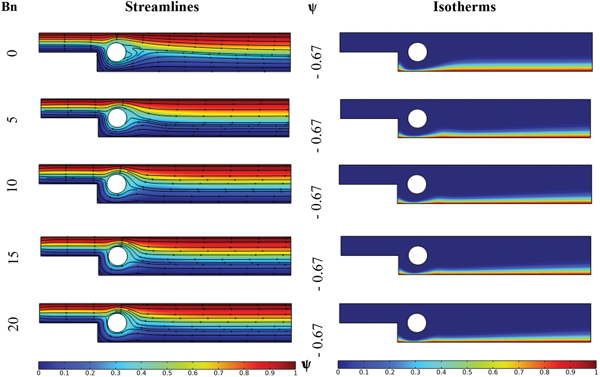
Figure 12: Streamlines and isotherms for various Bingham number at Re = 100, Ha = 0, γ = 0, and φ = 0.04
Fig. 13 presents velocity profiles captured at different longitudinal positions downstream of the cylindrical obstacle for different Bingham numbers. It is noticeable that the flow regime downstream of this obstacle is not established. Furthermore, all velocity profiles show that the maximum fluid velocity (peak of the profile) decreases as the Bingham number increases, implying a reduction in velocity in the middle of the BFS.
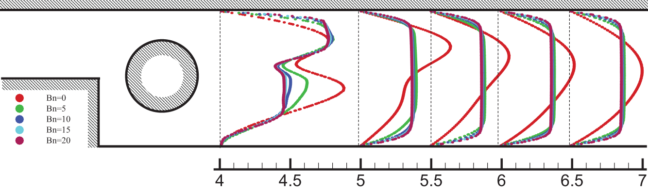
Figure 13: Velocity profile downstream of the cylinder at various longitudinal positions for different Bingham numbers at Ha = 0, Re = 100, and φ = 0.04
However, the flow within this BFS becomes blocky, meaning that the maximum velocity of the profiles does not concentrate at a specific point but rather within a segment along the height of the BFS (bloc of maximal velocity). Indeed, this corresponds to an increased solidification of this type of fluid as the yield stress increases, along with a low velocity gradient in the middle of the BFS. According to the Bingham equation (Eq. (6)), this implies that the velocity tends to increase near the walls. Effectively, it has been observed that increasing the Bingham number leads to an increase in velocity near the walls, where the velocity gradient reaches more pronounced values. As this non-Newtonian fluid’s viscosity is not fixed based on velocity, or more precisely, on the velocity gradient, in our situation, viscosity tends to increase in the middle of the BFS, while decreasing near the walls despite the presence of friction. This interpretation explains the reduction in the thickness of the thermal boundary layer observed in Fig. 12. Nevertheless, we consider that overall the flow is reduced as velocity decreases in the majority of the BFS. Therefore, we suggest using Bingham nanofluid in such thermal situations if the aim is to decrease boundary layer thickness.
Fig. 14 presents the distribution of the local Nusselt number along the hot wall for different Bingham numbers. Along this entire wall, the Nusselt number increases as the Bingham number rises, indicating the significance of convective heat transfer and the cooling process in the immediate vicinity of this hot wall. This is primarily due to the exceptional increase in velocity near the BFS profiles under the effect of visco-plasticity (fluid with yield stress). On the other hand, it is observed that if the Nusselt number had been plotted along a line passing through the BFS axis where the velocity significantly decreased, the Nusselt number would have decreased due to low inertia.
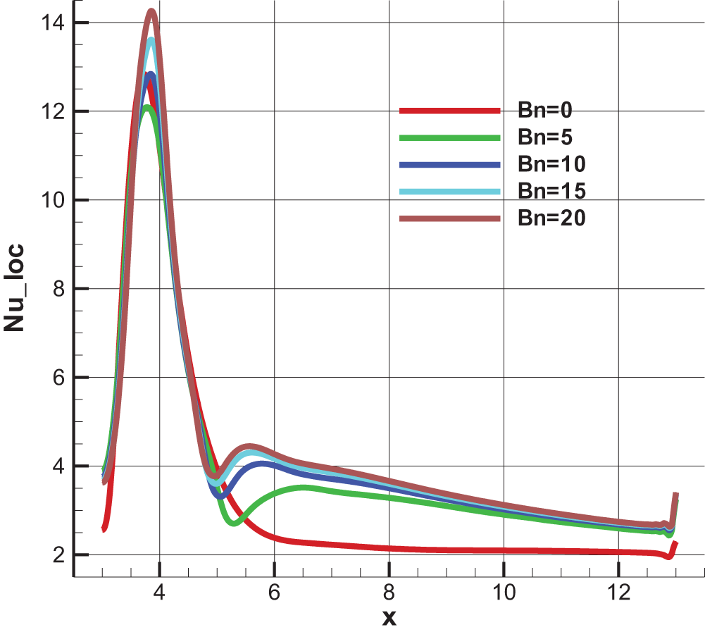
Figure 14: Local Nusselt number along the heated wall for different Bingham number at Re = 100, Ha = 0, γ = 0, and φ = 0.04
This paper presents a numerical investigation into the behavior of a yield stress nanofluid within a backward-facing step (BFS), examining the influence of several parameters, including inertia, magnetic field and its inclination, nanoparticle concentration, and yield stress. The key conclusions derived from the results can be summarized as follows:
• The flow intensity increases as the velocity of the nanofluid within the BFS rises. Additionally, the thermal boundary layer becomes thinner with higher nanofluid velocity, indicating an improvement in convective heat transfer.
• A horizontal magnetic field adversely affects the flow within the BFS, leading to a reduction in the heat transfer rate compared to cases without a magnetic field.
• Unlike the magnetic flux density, the inclination angle of the magnetic field has a positive impact on the nanofluid flow and heat transfer rate. Notably, inclining the magnetic field to 90° results in a significant enhancement in heat transfer.
• Incorporating nanoparticles into the base fluid substantially improves heat transfer within the BFS. However, no observable effect on the hydrodynamic behavior has been noted.
• The yield stress of the Bingham fluid generally diminishes flow intensity and suppresses the vortex formation downstream of the cylindrical obstacle. Nonetheless, thermal analysis reveals a reduction in thermal boundary layer thickness, resulting in an inevitable increase in velocity.
• All velocity profiles indicate that the peak fluid velocity decreases as the Bingham number increases, reflecting reduced velocity in the central region of the BFS. Overall, the flow diminishes as velocity decreases across most of the BFS.
• Utilizing Bingham nanofluids in thermal applications is recommended to reduce boundary layer thickness and thereby enhance heat transfer rates, particularly near heated surfaces.
Acknowledgement: None.
Funding Statement: The authors received no specific funding for this study.
Author Contributions: The authors confirm contribution to the paper as follows: study conception and design: Karim Amrani, Eugenia Rossi di Schio, Mohamed Bouzit, Abderrahim Mokhefi, Abdelkader Aris, Cherif Belhout and Paolo Valdiserri; analysis and interpretation of results: Karim Amrani, Eugenia Rossi di Schio, Mohamed Bouzit, Abderrahim Mokhefi, Abdelkader Aris, Cherif Belhout and Paolo Valdiserri; draft manuscript preparation: Karim Amrani, Eugenia Rossi di Schio, Mohamed Bouzit, Abderrahim Mokhefi, Abdelkader Aris, Cherif Belhout and Paolo Valdiserri. All authors reviewed the results and approved the final version of the manuscript.
Availability of Data and Materials: The data that support the findings of this study are available from the first author, K.A., upon reasonable request.
Ethics Approval: Not applicable.
Conflicts of Interest: The authors declare no conflicts of interest to report regarding the present study.
References
1. Gallo M, Boersma BJ, Colonna P. Liquid cooling enhancement by means of magnetic fields. Appl Therm Eng. 2013;61(2):871–7. doi:10.1016/j.applthermaleng.2013.05.036. [Google Scholar] [CrossRef]
2. Marcinichen JB, Olivier JA, de Oliveira V, Thome JR. A review of on-chip micro-evaporation: experimental evaluation of liquid pumping and vapor compression driven cooling systems and control. Appl Energy. 2012;92(3):147–61. doi:10.1016/j.apenergy.2011.10.030. [Google Scholar] [CrossRef]
3. Jiang W, Zhao J, Rao Z. Thermal performance enhancement and prediction of narrow liquid cooling channel for battery thermal management. Appl Energy. 2022;171:107250. doi:10.1016/j.ijthermalsci.2021.107250. [Google Scholar] [CrossRef]
4. Choi US. Enhancing thermal conductivity of fluids with nanoparticles, developments and application of non-newtonian flows. ASME J Heat Transfer. 1995;66:99–105. [Google Scholar]
5. Rafati M, Hamidi AA. Application of nanofluids in computer cooling systems (heat transfer performance of nanofluids). Appl Therm Eng. 2012;45(6):9–14. doi:10.1016/j.applthermaleng.2012.03.028. [Google Scholar] [CrossRef]
6. Mohammeda HA, Al-aswadia AA, Shuaiba NH, Saidurb R. Convective heat transfer and fluid flow study over a step using nanofluids: a review. Renew Sust Energy Rev. 2011;15(6):2921–39. doi:10.1016/j.rser.2011.02.019. [Google Scholar] [CrossRef]
7. Qi C, Tang J, Fan F, Yan Y. Effects of magnetic field on thermo-hydraulic behaviors of magnetic nanofluids in CPU cooling system. Appl Therm Eng. 2020;179(1):115717. doi:10.1016/j.applthermaleng.2020.115717. [Google Scholar] [CrossRef]
8. Hussain S, Ahmed SE. Unsteady MHD forced convection over a backward facing step including a rotating cylinder utilizing Fe3O4-water ferrofluid. J Magnet Magnet Mat. 2019;484(12):356–66. doi:10.1016/j.jmmm.2019.04.040. [Google Scholar] [CrossRef]
9. Mokhefi A, di Schio ER. Effect of a magnetic field on the Couette forced convection of a Buongiorno’s nanofluid over an embedded cavity. JP J Heat Mass Transfer. 2022;30:89–104. [Google Scholar]
10. Sharma AK, Tiwari AK. Rheological behavior of nanofluids: a review. Renew Sust Energy. 2016;53:779–91. doi:10.1016/j.rser.2015.09.033. [Google Scholar] [CrossRef]
11. Mokhefi A, Bouanini M, Elmir M. Numerical simulation of laminar flow and heat transfer of a Non-Newtonian nanofluid in an agitated tank. J Heat Technol. 2021;39(1):251–61. doi:10.18280/ijht.390128. [Google Scholar] [CrossRef]
12. Ali FH, Hamzah HK, Egab K, Arıcı M, Shahsavar A. Non-Newtonian nanofluid natural convection in a U-shaped cavity under magnetic field. Int J Mech Sciences. 2020;186(5):105887. doi:10.1016/j.ijmecsci.2020.105887. [Google Scholar] [CrossRef]
13. Chen L, Asai K, Nonomura T, Xi G, Liu T. A review of Backward-Facing Step (BFS) flow mechanisms, heat transfer and control. Therm Scid Eng Prog. 2018;6(3):194–216. doi:10.1016/j.tsep.2018.04.004. [Google Scholar] [CrossRef]
14. Lan H, Armaly BF, Drallmeier JA. Three-dimensional simulation of turbulent forced convection in a duct with backward-facing step. Int J Heat Mass Trans. 2009;52:1690–700. doi:10.1016/j.ijheatmasstransfer.2008.09.022. [Google Scholar] [CrossRef]
15. Mokhefi A, di Schio ER, Valdiserri P, Biserni C, Derbal D. Numerical study of the Thermo-hydrodynamic behavior of a non-Newtonian nanofluid in a backward facing step. Int J Phys: Conf Ser. 2024;2685(1):012074. doi:10.1088/1742-6596/2685/1/012074. [Google Scholar] [CrossRef]
16. Hussanan A, Qasim M, Chen ZM. Heat transfer enhancement in sodium alginate based magnetic and non-magnetic nanoparticles mixture hybrid nanofluid. Physica A: Stat Mech Appl. 2020;550(4):123957. doi:10.1016/j.physa.2019.123957. [Google Scholar] [CrossRef]
17. Selimefendigil F, Öztop HF. Hydro-thermal performance of CNT nanofluid in double backward facing step with rotating tube bundle under magnetic field. Int J Mech Sci. 2020;185:105876. doi:10.1016/j.ijmecsci.2020.105876. [Google Scholar] [CrossRef]
18. Aly AM, Mohamed EM, Alsedais N. Double-diffusive convection from a rotating rectangle in a finned cavity filled by a nanofluid and affected by a magnetic field. Int Comm Heat Mass Transfer. 2021;126:105363. doi:10.1016/j.icheatmasstransfer.2021.105363. [Google Scholar] [CrossRef]
19. Mokaddes M, Akhter AR, Alim MA. Hydromagnetic mixed convection in a triangular shed filled by nanofluid and equipped with rectangular heater and rotating cylinders. Int J Thermofluids. 2021;11:100105. doi:10.1016/j.ijft.2021.100105. [Google Scholar] [CrossRef]
20. Ghachem K, Selimefendigil F, Alshammari BAM, Maatki C, Kolsi L. Coupled effects of using magnetic field, rotation and wavy porous layer on the forced convection of hybrid nanoliquid flow over 3D-Backward facing step. Nanomaterials. 2022;12(14):2466. doi:10.3390/nano12142466. [Google Scholar] [PubMed] [CrossRef]
21. Klazly M, Mahabaleshwar US, Bognár G. Comparison of single-phase Newtonian and non-Newtonian nanofluid and two-phase models for convective heat transfer of nanofluid flow in backward-facing step. J Molecular Liquids. 2022;361:119607. doi:10.1016/j.molliq.2022.119607. [Google Scholar] [CrossRef]
22. Akrama S, Nadeem S, Hussain A. Effects of heat and mass transfer on peristaltic flow of a Bingham fluid in the presence of inclined magnetic field and channel with different wave forms. J Magnet Magnet Mat. 2014;362:184–92. doi:10.1016/j.jmmm.2014.02.063. [Google Scholar] [CrossRef]
23. Javadpour A, Najafi M, Javaherdeh K. Effect of magnetic field on forced convection heat transfer of a non-Newtonian nanofluid through an annulus: an experimental study. Heat Mass Transf. 2018;54(11):3307–16. doi:10.1007/s00231-018-2361-z. [Google Scholar] [CrossRef]
24. Alizadeh R, Dorfaki V, Ameri A, Valizadeh Ardalan M, Javidi Sarafan M. Heat transfer and pressure drop in a sinus blowing of copper oxide-water non-Newtonian nanofluid in a sudden expansion process in the presence of variable magnetic field: a numerical solution. Energy Sour. 2020;46(1):16521–44. doi:10.1080/15567036.2020.1817195. [Google Scholar] [CrossRef]
25. Rawa MJH, Abu-Hamdeh NH, Golmohammadzadeh A, Shahsavar Goldanlou A. An investigation on effects of blade angle and magnetic field on flow and heat transfer of non-Newtonian nanofluids: a numerical simulation. Int Comm Heat Mass Transfer. 2021;120:105074. doi:10.1016/j.icheatmasstransfer.2020.105074. [Google Scholar] [CrossRef]
26. Kherroubi S, Benkahla YK, Labsi N, Ragui K, Bensaci A, Boutra A, et al. Two-and three-dimensional comparative study of heat transfer and pressure drop characteristics of nanofluids flow through a ventilated cubic cavity (part I: newtonian nanofluids). J Therm Anal Calorim. 2021;144(2):623–46. doi:10.1007/s10973-020-10318-5. [Google Scholar] [CrossRef]
27. Lahlou S, Labsi N, Benkahla YK, Boudiaf A, Ouyahia SE. Flow of viscoplastic fluids containing hybrid nanoparticles: extended Buongiorno’s model. J Non-Newtonian Fluid Mech. 2020;281(5):104308. doi:10.1016/j.jnnfm.2020.104308. [Google Scholar] [CrossRef]
28. Kazemi MA, Javanmard M, Taheri MH, Askari N. Heat transfer investigation of the fourth-grade non-Newtonian MHD fluid flow in a plane duct considering the viscous dissipation, joule heating and forced convection on the walls. SN Appl Sci. 2020;2(10):1752. doi:10.1007/s42452-020-03567-4. [Google Scholar] [CrossRef]
29. Borrelli A, Giantesio G, Patria MC. Exact solutions in MHD natural convection of a Bingham fluid: fully developed flow in a vertical channel. J Therm Anal Calorim. 2022;147(10):5825–38. doi:10.1007/s10973-021-10882-4. [Google Scholar] [CrossRef]
30. Vishalakshi AB, Maranna T, Mahabaleshwar US, Laroze D. An effect of MHD on non-Newtonian fluid flow over a porous stretching/shrinking sheet with heat transfer. Appl Sci. 2022;12(10):4937. doi:10.3390/app12104937. [Google Scholar] [CrossRef]
31. Dawar A, Islam A, Alshehri A, Bonyah E, Shah Z. Heat transfer analysis of the MHD stagnation point flow of a non-newtonian tangent hyperbolic hybrid nanofluid past a non-isothermal flat plate with thermal radiation effect. J Nanomater. 2022;2022(1):4903486. doi:10.1155/2022/4903486. [Google Scholar] [CrossRef]
32. Rehman S, Hashim, Alqahtani S, Alshehery S. Modeling a non-Newtonian nanofluid flow between intersecting planes with slip mechanism. Continuum Mech Thermo. 2023;35(1):61–80. doi:10.1007/s00161-022-01162-z. [Google Scholar] [CrossRef]
33. Boujelbene M, Rehman S, Hashim, Alqahtani S, Eldin SM. Optimizing thermal characteristics and entropy degradation with the role of nanofluid flow configuration through an inclined channel. Alexandria Eng J. 2023;69:85–107. doi:10.1016/j.aej.2023.01.026. [Google Scholar] [CrossRef]
34. Brinkman HC. The viscosity of concentrated suspensions and solutions. J Chem Phys. 1952;20(4):571–81. doi:10.1063/1.1700493. [Google Scholar] [CrossRef]
35. Maxwell JC. A treatise on electricity and magnetism. Cambridge, UK: Oxford Univ Press; 1873. vol. II, p. 54. [Google Scholar]
36. Rossi di Schio E, Impiombato AN, Mokhefi A, Biserni C. Theoretical and numerical study on buongiorno’s model with a couette flow of a nanofluid in a channel with an embedded cavity. Appl Sci. 2022;12(15):7751. doi:10.3390/app12157751. [Google Scholar] [CrossRef]
37. Taylor C, Hood P. A numerical solution of the Navier-Stokes equations using the finite element technique. Comput Fluids. 1973;1(1):73–100. doi:10.1016/0045-7930(73)90027-3. [Google Scholar] [CrossRef]
38. Dechaumphai P. Finite element method in engineering. 2nd ed. Bangkok: Chulalongkorn University Press; 1999. [Google Scholar]
Cite This Article
 Copyright © 2025 The Author(s). Published by Tech Science Press.
This work is licensed under a Creative Commons Attribution 4.0 International License , which permits unrestricted use, distribution, and reproduction in any medium, provided the original work is properly cited.
 Downloads
 Citation Tools