
 Submit a Paper
 Propose a Special lssue
 Open Access
ARTICLE
Numerical Simulation of the Flow and Heat Transfer in Novel Circumfluent Cyclone Separator during High-Temperature Converter Gas Recovery
1 State Key Laboratory of High Temperature Gas Dynamics, Institute of Mechanics, Chinese Academy of Sciences, Beijing, 100190, China
2 School of Engineering Science, University of Chinese Academy of Sciences, Beijing, 100049, China
* Corresponding Author: Sen Li. Email:
Frontiers in Heat and Mass Transfer 2025, 23(1), 163-184. https://doi.org/10.32604/fhmt.2024.059740
Received 15 October 2024; Accepted 26 November 2024; Issue published 26 February 2025
 View Full Text
 Download PDF
Abstract
In the novel fully dry converter gas recovery process, a novel circumfluent cyclone separator with an evaporation heating surface can simultaneously realize the dust removal and sensible heat recovery of converter gas. For this equipment, the distributions of internal flow and wall heat transfer affect the efficiency of dust removal and sensible heat recovery. In this study, based on on-site operation tests, the distributions of internal flow and wall heat transfer in the circumfluent cyclone separator are studied by numerical simulation. The results indicate that the flow rate proportions in different regions of the circumfluent cyclone separator remain constant during the steelmaking process, approximately 80.1% of the converter gas flows through the cone chamber, and 15.4% of the converter gas flows through the annular chamber. The heat transfer rate proportions on the walls of different regions of the circumfluent cyclone separator remain constant during the steelmaking process, and the heat transfer rate proportions on the walls of the cone chamber, straight shell, shell head and outlet pipe are 40.2%, 27.0%, 17.6% and 15.2%, respectively.Keywords
Glossary/Nomenclature/Abbreviations
| Density | |
| u | Velocity |
| Turbulence fluctuation velocity | |
| x | Axis |
| Kronecker factor | |
| t | Time |
| Specific heat | |
| Thermal conductivity | |
| Viscosity | |
| Quality | |
| Volume | |
| I | Turbulence intensity |
| DH | Hydraulic diameter |
| Particle position | |
| g | Gravitational acceleration |
| Relaxation time | |
| d | Diameter |
| Drag coefficient | |
| Heat flux | |
| Convection heat transfer coefficient | |
| Temperature | |
| Absorption coefficient | |
| Pressure | |
| Surface area | |
| Emissivity | |
| Stefan–Boltzmann constant | |
| M | Mass flow rate |
| Flow rate proportion | |
| Heat transfer rate proportion | |
| Q | Heat transfer rate |
| Re | Reynolds number |
| Relative Reynolds number | |
| p | Particle |
Basic oxygen furnace is the most widely employed method, a great quantity of converter gas is formed [1], converter gas is mainly composed of CO and CO2 [2,3], and it carries a large amount of converter dust [4,5]. Converter gas containing CO is considered a fuel with recycling value [6], but the converter gas can easily explode. To prevent converter gas explosions and remove dust in gas recovery process, converter gas is currently cooled from 850°C to 60°C by spraying water or mist, which results in a great quantity of sensible heat from converter gas cannot be recovered. In order to effectively recover sensible heat from converter gas in the converter gas recovery process, a novel fully dry converter gas recovery process is presented by the Chinese Academy of Sciences (see Fig. 1) [7]. A precision explosion-proof system is introduced, and a cyclone separator with the evaporation heating surface is used to remove dust and recover sensible heat and replace wet dust removal. In this novel process, the cyclone separator is required to have a low pressure drop and high heat exchange capacity, and a novel circumfluent cyclone separator is applied, which has high dust removal efficiency and a low pressure drop [8]. The structure of a circumfluent cyclone separator is different from that of a conventional cyclone, where an inner chamber is placed in this type of cyclone to improve the gas flow pattern, and the gas inlet tangentially connects to the lower part of the inner chamber through the straight shell (see Fig. 2).
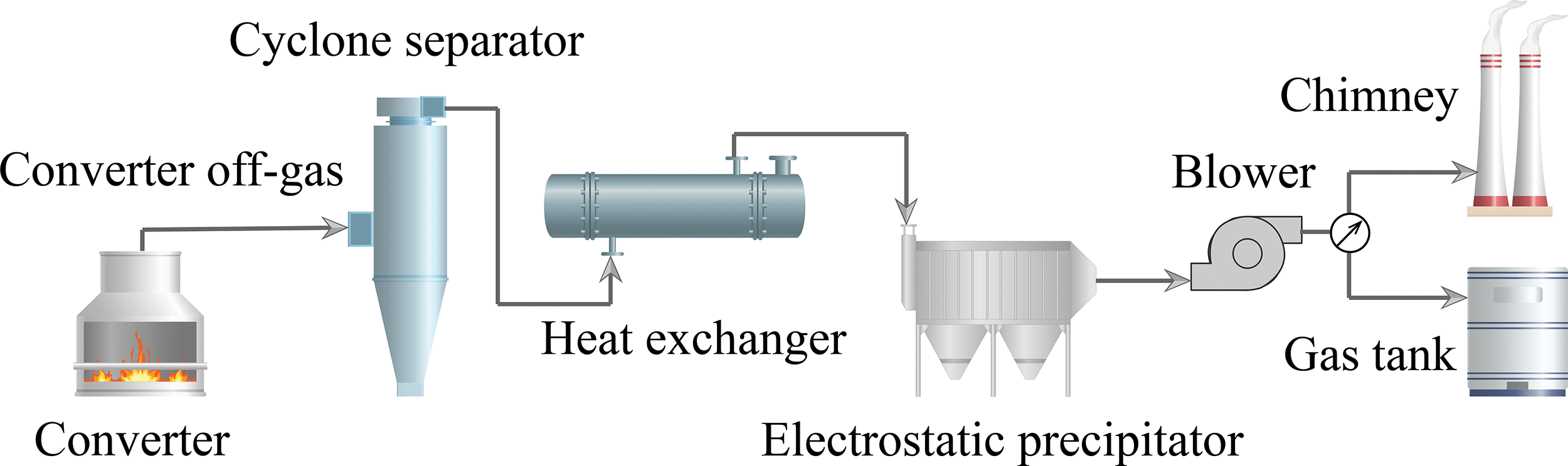
Figure 1: Novel fully dry converter gas recovery process
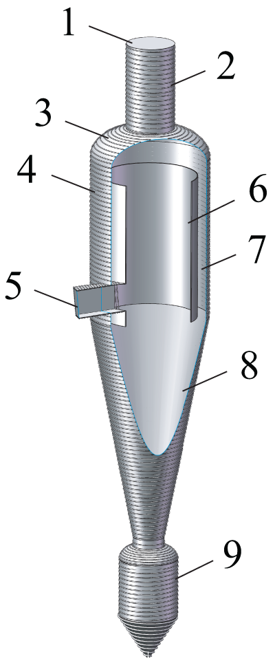
Figure 2: The circumfluent cyclone separator structure 1. Outlet; 2. Outlet pipe; 3. Shell head; 4. Straight shell; 5. Inlet; 6. Inner chamber; 7. Annular chamber; 8. Cone chamber; 9. Dust hopper
For the circumfluent cyclone separator, the dust removal and heat transfer capacities in different regions (see Fig. 2) differ, thus, the flow distributions between these regions significantly affect the overall dust removal and heat transfer efficiency. Furthermore, the heat transfer capacity of the circumfluent cyclone mainly depends on the evaporation heating surface, and the distribution of wall heat transfer intensity can provide a reference for reasonably arranging the evaporation heating surface. Therefore, the distributions of internal flow and wall heat transfer in the circumfluent cyclone separator are of great significance to improve dust removal and sensible heat recovery for converter gas. However, in practical oxygen blowing steelmaking, the converter gas flow rate, temperature, and component content vary with the oxygen blowing time [2], the unsteady conditions make it difficult to determine the distribution laws of internal flow and wall heat transfer.
At present, the studies on cyclone separators are mostly focused on the application in fluidized bed processes and the dust removal performance [9–12]. However, some scholars have investigated the heat transfer capacities of cyclone separators. Karagoz et al. [13] researched flow and heat transfer in a conventional cyclone. They concluded that with the increase of inlet velocity, the heat transfer from the gas to the cyclone separator wall increases. Nag et al. [14] reported the effects of adding the fins on heat transfer characteristics of a conventional cyclone separator. They found that the heat transfer coefficient decreases with the addition of fins, but the total heat exchange intensifies with the increased heating area, which exceeded the compensation for this decline. Dasar et al. [15] introduced the installation of fins to improve the dust removal performance of a conventional cyclone and to utilize the cyclone separator as heat exchanger. They found that the separation efficiency increases by 15% and the water temperature of the heating surface increases by 15°C after the fins are arranged on the wall. Yohana et al. [16] researched the effect of vortex finder (a structure of conventional cyclone) length on heat transfer in the conventional cyclone and found that the temperature distribution in the center of the cyclone decreases by 3 K with the increase of vortex finder length. Liu et al. [17] proposed a new process for recovering waste heat from slag particles using a conventional cyclone. In the above studies, some heat transfer characteristics of conventional cyclone separators are revealed. Furthermore, some scholars have also conducted research on circumfluent cyclone separators. Duan et al. [8] studied the gas–solid flow in a circumfluent cyclone separator and compared it with that in a conventional cyclone separator. It is found that this type of cyclone has the advantages of a more stable flow field, a larger gas-solid separation region and a shorter gas flow path. Wang et al. [18] found through experiments that the separation efficiency of the circumfluent cyclone separator is 8% higher than that of the conventional cyclone separator within the gas inlet velocity range of 12~26 m/s. Duan et al. [19] found that in a certain range, the outer straight shell height of circumfluent cyclone separator has an optimum value, which can have higher collection efficiency and lower pressure drop. Zhang et al. [20] proposed a new circumfluent circulatory separator system (CCSS) based on two circumfluent cyclone separators.
The above literature reports many studies on the flow and heat transfer characteristics of conventional cyclone separators. Some outstanding performances of the circumfluent cyclone compared with the conventional cyclone are also reported in these literatures. However, few scholars use the circumfluent cyclone separator with outstanding performance for heat exchange. The research on the heat transfer characteristics of circumfluent cyclone separators is still in a blank state. More importantly, the internal flow distribution of a circumfluent cyclone separator is complex and significantly impacts dust removal and heat transfer performance. However, many researches [18,20] on the circumfluent cyclone separator by experimental methods. It is difficult to observe the internal flow inside a cyclone through experimental means. Duan et al. [8] analyzed the internal flow field inside a circumfluent cyclone through numerical calculation, but did not reveal the internal flow distribution. At present, the studies have not revealed the flow distribution inside the circumfluent cyclone separator, which leads to the lack of basis for the performance optimization of this equipment.
In order to improve converter dust removal and sensible heat recovery, it is necessary to first investigate the distributions of internal flow and wall heat transfer in the circumfluent cyclone separator during the steelmaking process. In this study, under various steelmaking conditions, the distributions of the high-temperature converter gas flow and wall heat transfer in the circumfluent cyclone separator are studied by numerical simulation, and provide the basis for optimizing the performance of this dust removal and heat transfer integrated equipment.
Fig. 2 shows the structure of the circumfluent cyclone separator applied in the novel fully dry converter gas recovery process. An inner chamber is arranged in the cyclone separator, and the space between the inner chamber wall and the straight shell wall is referred to as the annular chamber (7). The dusty gas flows into the cyclone from the bottom of the inner chamber (5). Converter gas flows into the inner chamber to remove larger dust particles. Subsequently, the converter gas flows into the cone chamber (8) and the annular chamber (7) to further remove small dust particles. Finally, the purified converter gas flows out through the outlet (1). As for the structural dimensions of the circumfluent cyclone, the inlet is a rectangle with a length of 1 m and a width of 0.9 m. The inlet pipe is tangentially connected to the bottom of the inner chamber through the outer straight shell and is inclined upward by 5° relative to the horizontal. The diameter of the outlet pipe is 1.6 m. The diameters of the inner chamber and the outer straight shell are 3.5 and 4.1 m, respectively. They both have a length of 4.5 m. The cyclone separator cone length is 7.8 m.
Compared to a conventional cyclone separator, the arrangement of an inner chamber has the following advantages: I) the arrangement of the inner chamber forms an annular chamber (7) in the cyclone separator, and part of the gas will enter the annular chamber for further gas-solid separation before flowing out of the cyclone separator, thereby improving the dust removal efficiency; II) due to the existence of the inner chamber wall, the common vertical vortex and short-circuit flow in a conventional cyclone separator are eliminated, and the internal flow stability is improved; III) some gas can directly flow out of the cyclone separator after passing through the dust removal in the inner chamber, shortening the flow path of the gas, and effectively reducing the pressure drop of the equipment.
Fig. 3 shows the grid division in the computing domain. For the complex and irregular geometry of the circumfluent cyclone separator, the computing domain is modeled by polyhedral grids using unstructured grid technology to capture the detailed structure of the complex geometric model. The total number of grids in the computing domain is determined by defining the maximum cell length.
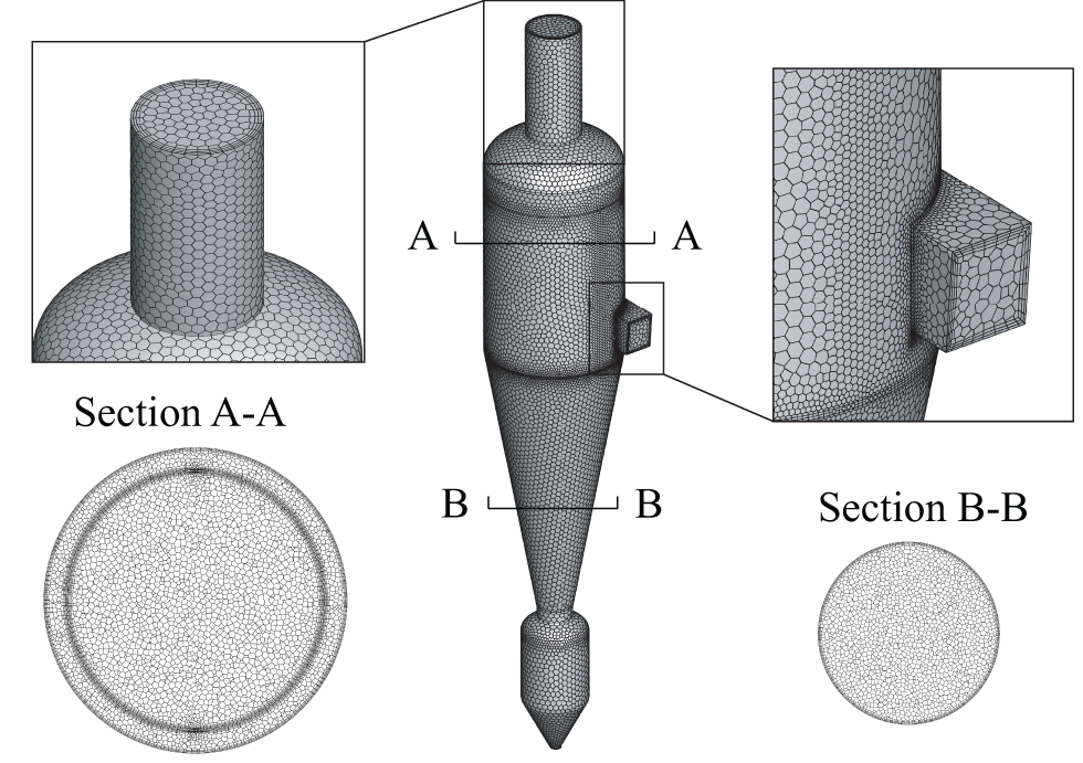
Figure 3: Scheme grids of the computing domain
2.2.1 Continuous Phase Flow Model
In the simulation, the turbulence model: Reynolds stress model (RSM) is used to calculate the internal flow in the circumfluent cyclone. The strongly swirling flow inside a cyclone separator shows strong Reynolds stress anisotropy. However, most turbulence models such as k-epsilon and k-omega are based on the isotropic assumption of turbulence, that is, the turbulence fluctuation velocity is the same (
where
the stress diffusion term:
the shear production term:
the pressure-strain term:
the dissipation term:
and the source term: S.
In the mathematical model, the flow turbulence intensity I is calculated by the following equations:
where DH is the hydraulic diameter, Re is the Reynolds number, and the Reynolds numbers under various conditions are estimated based on the on-site measured data of converter gas at the cyclone separator inlet.
Converter gas is a gas mixture, and a mixing law is employed to express the physical properties of the converter gas; for the mixing law expression, see Eqs. (8) and (9). The variations in the physical properties of each component with respect to temperature are obtained by fitting calculations (see Table 1).
where
where

2.2.2 Discrete Phase Flow Model
The Euler–Lagrange method can comprehensively consider the turbulence, force, and heat transfer during particle movement. In the simulation, the discrete phase flow model (DPM) is chosen to simulate the particle trajectory. Based on the Euler–Lagrange method, the DPM is suitable for simulating converter dust particle motion [23]. Since the dust content (volume fraction) of the converter gas is smaller than 10%, the interaction between particles and the influence of particles on gas flow can be ignored in the calculation. In addition, the dust particles flowing in the cyclone are mainly affected by the gravity and drag force, while other forces have little effect on the particles [8]. In DPM, the governing equations of a single particle flow are as follows:
2.2.3 Convection Heat Transfer Model
The heat transfer coefficient between gas and wall is calculated by the following equation:
where
2.2.4 Radiation Heat Transfer Model
In the converter gas, the gases CO and CO2 and dust particles have strong thermal radiation capabilities. To accurately calculate the propagation of radiation, it is necessary to solve the radiation heat transfer equation (RTE) [24,25], and the high precision solution of the RTE can be calculated through the discrete ordinates (DO) method [26]. In this study, the DO method is used for the RTE solution.
The weighted-sum-of-gray-gases model (WSGGM) provides the absorption coefficient and the weighting factor of each gray gas of converter gas to be directly applied to the RTE [27,28]. Determining the total emissivity is the starting point for generating the correlations of the WSGGM, and the total emissivity of the converter gas (
where J is the quantity of gray gases in the converter gas;
where
2.2.5 Discrete Phase Heat Transfer Model
Converter dust particles play a certain role in the heat exchange process of converter gas. To simulate the particles heat transfer, Eq. (21) is obtained by linking the particle temperature to convection and radiation heat transfer [30]:
where
During converter steelmaking, the variations in the flow rate, the concentration and the temperature of gas at the cyclone separator inlet with time as shown in Fig. 4. During practical operation, the pressure at the cyclone separator outlet is kept at −600 Pa. The evaporation heating surface is arranged on the cyclone separator wall to produce saturated steam at 2.4 × 10⁵ kPa, and the wall surface temperature is kept at 400 K in the simulation.
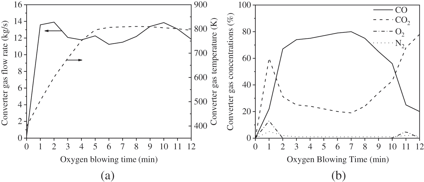
Figure 4: The parameter variations of converter gas with blowing oxygen time at the inlet of the circumfluent cyclone separator [31]. (a) The initial flow rate and temperature; (b) The initial concentrations
The particle size distribution of dust in converter gas was determined with a laser particle size analyzer (Winner2005A), and the measured results are shown in Fig. 5. The dust particle size is suitable for the Rosin–Rammler distribution. The maximum diameter of the particles is 100 μm, the minimum diameter of the particles is 0.20 μm, the mean diameter of the particles is 48 μm, and the spread parameter is 1.75.
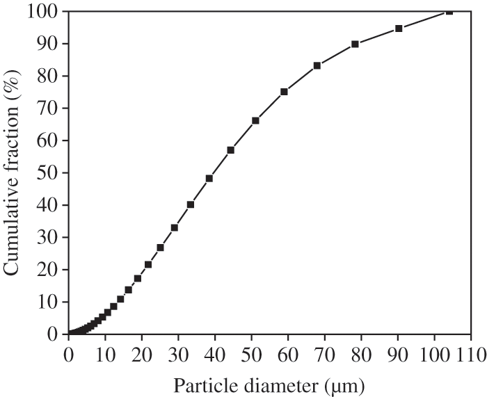
Figure 5: The particle size distribution of the converter dust
We use FLUENT based on finite volume method to simulate the internal flow and heat transfer in the circumfluent cyclone. The diffusion terms of the governing equations are solved through the central-differenced method. The gradient discretization format uses the Least Squares Cell-Based method. The pressure term uses the Pressure Staggered Option method. The Quadratic Upstream Interpolation for Convective Kinetics method is selected to solve the momentum, convection, energy and all other terms.
2.4 Validation of the Grid Independence and Numerical Models
Four-level grids of 159,129 cells, 227,836 cells, 339,629 cells and 606,167 cells are chosen for the verification of grid independence, and the simulation results show that the converter gas temperature at the cyclone separator outlet is 642.2, 640.7, 637.4 and 637.2 K, respectively. This shows that the adequate independence is satisfied with the grid of 339,629 cells, we use the grid of 339,629 cells to calculate the internal flow and heat transfer in a circumfluent cyclone separator.
To validate the above simulation models, the simulated and on-site measured data of the converter gas temperature at the cyclone separator outlet are compared in Fig. 6. In this study, the on-site measured data of the temperature were measured by thermocouple. The gas temperature is not evenly distributed at the cyclone separator outlet, which causes the error between the temperature measured by a single thermocouple and the actual gas temperature. To reduce the error, we measured the temperatures at different locations in the outlet flow cross-section and calculated the average value of these temperatures. According to Fig. 6, the simulated results are in good agreement with the measured results, and the relative difference between them ranges from 1.7% to 6.3%, indicating that the model can reasonably describe the heat transfer and flow process in the circumfluent cyclone separator.
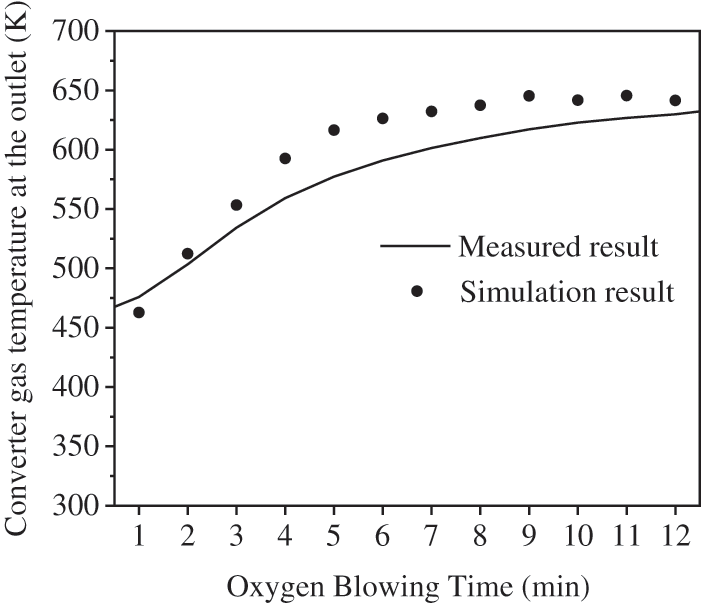
Figure 6: Comparison of the simulated and measured temperatures of the converter gas at the outlet of the cyclone separator during oxygen blowing
3.1 Flow Characteristics of Converter Gas in the Circumfluent Cyclone Separator
3.1.1 Gas Flow Path in the Circumfluent Cyclone Separator
In the circumfluent cyclone separator, converter gas is directly sent into the inner chamber. Fig. 7 presents the flow field in the circumfluent cyclone, indicating that the gas flow is complex. When gas tangentially flows into the inner chamber, the gas is divided into two gas streams: a gas stream (gas stream 1) first whirls downward into the cone chamber along the wall and flows back at the bottom of the cone chamber, then flows upward in the central region, and finally enters the inner chamber; the other gas stream (gas stream 2) whirls upward into the inner chamber along the wall; the above two gas streams eventually mix together and flow upward in the inner chamber. When the converter gas flows out of the inner chamber, the gas is again divided into two gas streams: a gas stream directly enters the shell head, and the other gas stream (gas stream 3) enters the annular chamber between the inner chamber wall and straight shell wall (see Fig. 2), recirculates and outflows from the upper of the annular chamber; the above two gas streams eventually mix together and outflow from the cyclone separator outlet. The flow paths of the above gas streams are presented in Fig. 8.
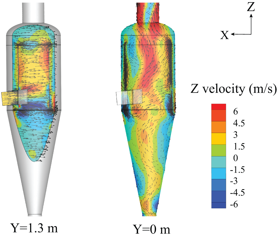
Figure 7: Converter gas flow field in the circumfluent cyclone separator
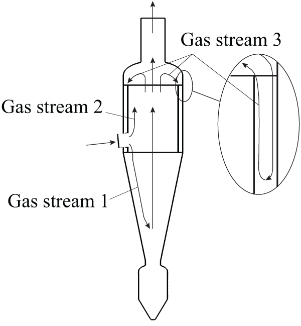
Figure 8: Diagram of gas stream flow paths in the circumfluent cyclone separator
3.1.2 Flow Rate Proportions of Different Gas Streams in the Circumfluent Cyclone Separator
The complex flow influences heat transfer on the wall of the circumfluent cyclone. The wall heat transfer distributions are influenced by the gas flow rates of the above mentioned gas streams in the different regions of the cyclone separator. In addition, the gas streams entering the cone chamber and annular chamber can complete further gas–solid separation to remove small dust particles, and the flow rates of gas streams 1 and 3 can affect the separation efficiency. Therefore, it is necessary to analyze the flow rates of these gas streams.
To analyze the flow rates in different regions of the circumfluent cyclone, the flow rate proportion (
where M0 is the mass flow rate of the converter gas entering the cyclone separator, kg/s; Mi is the mass flow rate of the different gas streams in the cyclone separator (see Fig. 8), kg/s.
According to the operating parameters of the cyclone separator (see Fig. 4), the gas flow field in the cyclone is simulated during oxygen blowing. Based on the gas flow direction, the mass flow rates of the different gas streams (see Fig. 8) in the cyclone separator are calculated, and the flow rate proportions of the different gas streams are provided in Fig. 9. The calculated results show that the gas flow proportions of different gas streams remain almost constant during the oxygen blowing time, and the mass flow rates
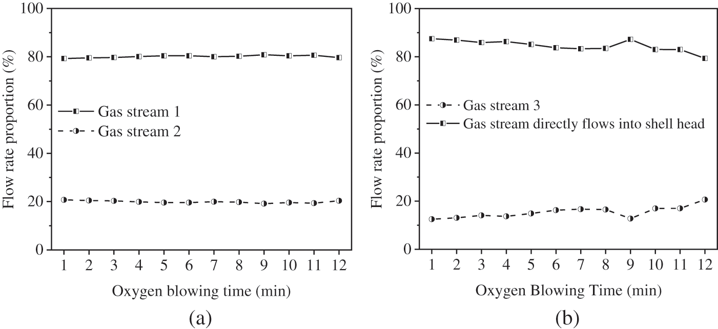
Figure 9: The flow rate proportions of different gas streams in the circumfluent cyclone separator
To investigate the cause of the flow rate proportions of gas streams 1 and 2 during oxygen blowing in Fig. 9a, it is necessary to first determine the interface between the two kinds of rotation regions in the cyclone. The rotational flow of the gas in a cyclone separator can be regarded as two kinds of regions: the outer side of rotation is the quasifree vortex region with approximate conservation of angular momentum, and the inner side of rotation is the quasiforced vortex region similar to rigid body rotation [32]. The interface between the two kinds of rotation regions in a cyclone separator is determined by the tangential velocity distribution. Fig. 10 shows the tangential velocity distribution of the gas rotation. The tangential velocity of the quasiforced vortex and the quasifree vortex varies inversely with the radius. The region of the tangential velocity peak in a flow section can be regarded as the boundary between the quasifree vortex region and quasiforced vortex region in this section, so by connecting the boundary (the tangential velocity peak) locations in different flow sections, the position and shape of the interface can be determined.
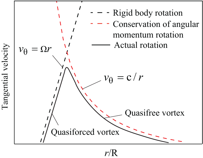
Figure 10: Tangential velocity of two kinds of ideal gas rotation and actual gas rotation [32]
Fig. 11 shows the distribution of the tangential velocity and the variation in the tangential acceleration (obtained by differentiating the tangential velocity) in the circumfluent cyclone. The location (r/R) of the tangential velocity peak (the location at which the tangential acceleration decreases to 0) in the flow section remains constant with the variation in the inlet Reynolds number, which indicates that the position and shape of the interface are constant with the variation in the inlet condition. Our study suggests that, to complete gas–solid separation, the Reynolds number (Re) in the cyclone separator reaches the range of the second self-modeling region (Re > 200000), and the gas flow enters a self-modeling state. When the gas stream enters the second self-modeling state, the flow pattern is no longer affected by the Reynolds number but is affected by the cyclone separator structure, so the interface can be affected by the separator structure rather than the inlet condition.
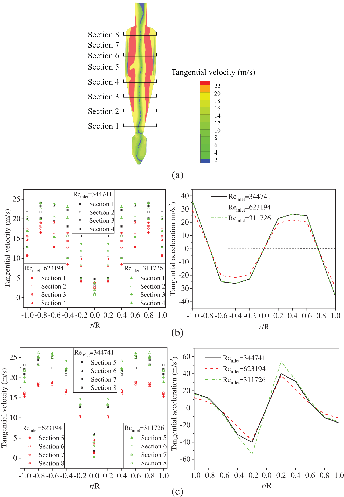
Figure 11: Tangential velocity distribution and tangential acceleration variation in the circumfluent cyclone separator. (a) Cloud plot of the tangential velocity; (b) Tangential velocity distribution and tangential acceleration variation in the cone chamber; (c) Tangential velocity distribution and tangential acceleration variation in the inner chamber
In addition, Fig. 11 shows that the peaks of tangential velocity in different flow cross-sections are at the same location (r/R). Connecting the same location (r/R) in different sections can form a regular shape. Therefore, the interface has a regular shape, and the position and shape of the interface can be easily determined. According to Fig. 11, the interface is located at 4/5 of the cross-sectional radius in the cone chamber, the shape is conical; the interface is located at 3/4 of the cross-sectional radius in the inner chamber, and the shape is cylindrical.
This paragraph explains the relationship between the interface mentioned above and the flow proportions of the gas streams. Due to the gas tightness of the cyclone separator, the gas can only be discharged from the top outlet pipe. According to Fig. 11a, the diameter of the interface is larger than that of the outlet pipe, and the inlet of the outlet pipeline is surrounded by the interface. Therefore, to be discharged from the outlet pipe, all the gas must flow through the interfaces along the radial velocity generated by the rotation. The flow diagrams of Streams 1 and 2 are presented in Fig. 12. In the figure, Interface 1 and Interface 2 are the interfaces of the quasifree vortex and the quasiforced vortex in the flow regions of Streams 1 and 2, respectively. The flow rate of the gas stream can be affected by pressure. For a cyclone separator, the axial pressure change is small, but the pressure drop along the radial direction from the outside to the inside of the rotation is large, and the radial positions of Interface 1 and Interface 2 are roughly the same (see Fig. 11), so Interface 1 and Interface 2 can be regarded as radial low-pressure outlets with approximate pressures of Gas Streams 1 and 2. Therefore, the flow rate ratio between Gas Streams 1 and 2 is close to the area ratio between Interface 1 and Interface 2.
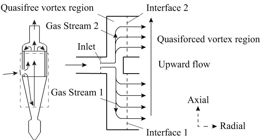
Figure 12: The flow diagram of Gas Streams 1 and 2
To obtain the flow rate ratio of the two streams affected by the interfaces, it is necessary to calculate the areas of the interfaces. According to the above analysis, the position and shape of the interface are constant, and the shape of the interface is regular (see Fig. 11), so the area of the interface can be calculated. By calculation, the area ratio of Interface 1 to Interface 2 is constant at 2.2:1, under the assumption of ignoring the temperature change caused by heat exchange, the flow rate ratio between Gas Gtreams 1 and 2 is close to 2.2:1.
The temperature difference between Gas Streams 1 and 2 can affect their flow ratio. The circumfluent cyclone structure is special, due to the separation of the annular chamber (see Fig. 2), it is difficult for Gas Stream 2 inside the inner chamber to efficiently transfer heat to the evaporation heating surface on the straight shell wall, causing a large temperature difference to exist between the Gas Streams 1 and 2. Based on the flow rate ratio of 2.2:1 obtained by the above analysis, the temperature ratio of Gas Streams 1 and 2 can be regarded as a coefficient of correction to obtain the flow rate ratio of the temperature is considered, and the result is shown in Fig. 13. The flow rate proportions of the temperature are considered to remain constant at 74.8% (Stream 1) and 25.2% (Stream 2). The actual flow rate proportions of Gas Streams 1 and 2 are 80.1% and 19.9%, respectively (see Fig. 9), and the errors between the analysis values and the actual values of flow rate proportions are small.
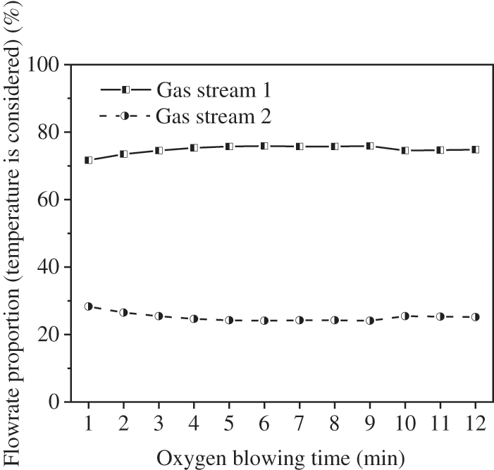
Figure 13: The flow rate ratio of the gas stream temperature is considered
The following discusses the cause of the flow proportion of Gas Stream 3 during oxygen blowing in Fig. 9b. When the gas flows out of the inner chamber, the gas stream directly enters the shell head, and the other gas stream (Gas Stream 3) enters the annular chamber, recirculates and then flows into the shell head (see Fig. 8). The two gas streams can be considered to flow out from the same region and converge in other regions, and the sectional areas of the flow regions can affect the flow rate distribution of the two gas streams. Generally, the flow rate ratio is close to the flow region cross-sectional area ratio of the two gas streams.
Fig. 14 shows the flow region cross-sectional area ratio of gas streams during oxygen blowing. The flow region cross-sectional area proportion of Gas Stream 3 is basically constant at 13.5%. The analysis shows that only one gas stream in the annular chamber performs reciprocating flow (see Fig. 8), and the flow region section of Gas Stream 3 is approximately half of the annular chamber section. Therefore, the proportion of the flow region cross-sectional area of Gas Stream 3 is related to the structure of the annular chamber. According to the above, the flow ratio is close to the cross-sectional area ratio of the flow region, so the flow proportion of Gas Stream 3 is basically constant and close to 13.5%. The actual flow rate proportion of Gas Stream 3 is 15.4% (see Fig. 9), and the error between the analysis value and the actual value is small.
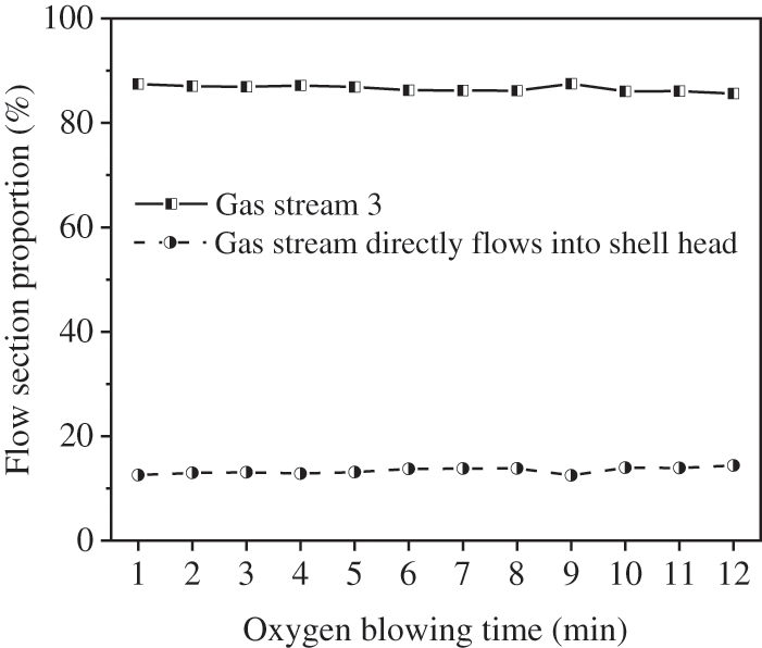
Figure 14: The cross-sectional area ratio of the flow region of the gas stream
The errors between the actual values and the analysis values of the gas stream flow rate proportions are small, so the above analysis is reliable. According to the above analysis, the flow rate proportions of the gas streams in different regions are not related to the inlet conditions but are affected by the circumfluent cyclone structure. Based on this feature, the dust separation and heat transfer performance of the circumfluent cyclone can be improved by adjusting the structure. For example, the gas entering the annular chamber can complete further gas–solid separation. By adjusting the structure of the annular chamber, more gas can enter it, which can improve the dust separation performance of the separator. Furthermore, the areas of the evaporation heating surface on the cone chamber and straight shell wall are larger (see Fig. 2). Through structural adjustment, more gas can enter the cone chamber and annular chamber to transfer heat, which can improve the heat transfer performance. Research on improving the dust separation and heat transfer performance of circumfluent cyclone separators by structural adjustment needs further research, and the analysis of this study provides references for future research.
3.1.3 The Distributions of Flow Rate Proportions in the Circumfluent Cyclone Separator
According to the above analysis, the flow proportions of gas streams in different regions of the cyclone remain constant during oxygen blowing, and the flow rate proportions distributions can be summarized as shown in Fig. 15. After converter gas enters the inner chamber, approximately 80.1% of the gas enters the cone chamber. This part of the gas generates an upward backflow in the cone chamber, enters the inner chamber again and mixes with the other 19.9% of the gas. When the converter gas flows out of the inner chamber, approximately 15.4% of the gas enters the annular chamber, recirculates and then enters the shell head. All the converter gas flows through the outlet pipe and flows out of the cyclone separator from the outlet.
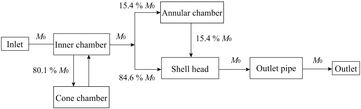
Figure 15: The distributions of converter gas flow rate proportions in the circumfluent cyclone separator
3.2 Heat Transfer Characteristics of Converter Gas in the Circumfluent Cyclone Separator
3.2.1 Heat Transfer Difference on the Wall of the Circumfluent Cyclone Separator
Fig. 16 shows the heat flux distribution on the wall surface of the circumfluent cyclone separator during the steelmaking process. The heat fluxes on the walls of the cone chamber and shell head are higher, and the heat flux on the straight shell is lower. Therefore, the heat exchange capacities on the walls of different regions differ. The main method of heat exchange between the converter gas and the wall surface is convection heat transfer, the heat transfer capacity is closely related to the gas flow rate. According to the flow rate proportions distributions (see Fig. 15), approximately 80.1% of the gas flows into the cone chamber, and all the gas flows through the shell head, so higher flow rates result in stronger heat transfer capacities on the walls of the cone chamber and shell head. Comparatively, only 15.4% of the gas enters the annular chamber, and a lower flow rate causes a poorer heat transfer capacity on the straight shell.
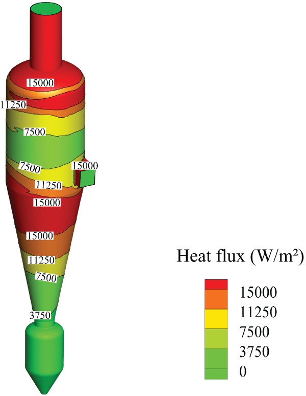
Figure 16: Heat flux distribution on the wall surface of the circumfluent cyclone separator
3.2.2 Heat Transfer Rate Proportions on the Walls of Different Regions
The difference in heat transfer between different regions makes the wall heat transfer of the circumfluent cyclone separator complex, which makes it difficult to reasonably arrange the evaporation heating surface. Therefore, it is necessary to analyze the heat transfer rate on the walls of different regions inside the circumfluent cyclone.
To analyze heat transfer rates of the different regions in the circumfluent cyclone, the heat transfer rate proportion (
where Qtotal is the heat transfer rate on the wall of whole cyclone separator, W; Qi is the heat transfer rate on the wall surface of different regions in the cyclone separator (see Fig. 2), W.
Fig. 17 shows the proportions of heat transfer rate on the walls of different regions. The heat transfer rate proportions remain constant during oxygen blowing. As mentioned above, the heat transfer between the converter gas and the wall is closely related to the flow rate, so constant flow rate proportions can keep the heat transfer rate proportions constant during oxygen blowing.
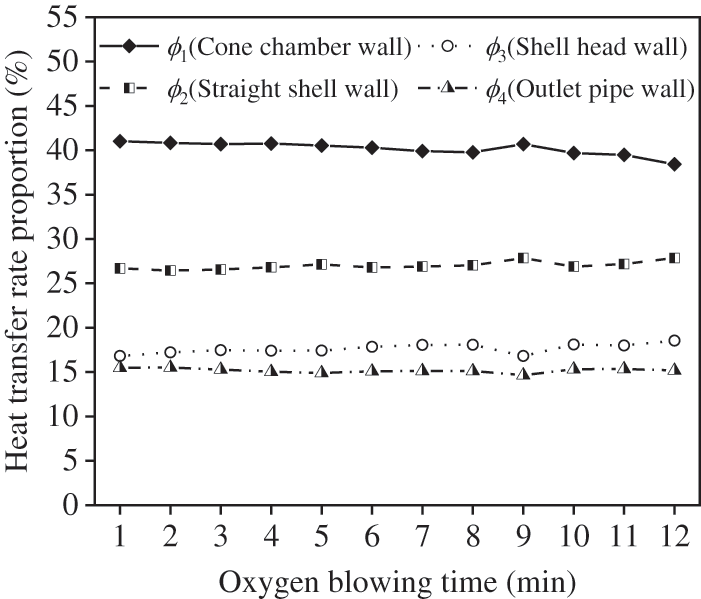
Figure 17: The proportions of heat transfer rate on the walls of different regions
3.2.3 The Distributions of Heat Transfer Rate Proportions on the Wall of the Circumfluent Cyclone Separator
According to the above analysis, the heat transfer rate proportions distributions on the wall of the circumfluent cyclone separator can be summarized as described in Fig. 18. The heat from converter gas is mainly transferred to the walls of the cone chamber, straight shell, shell head and outlet pipe (see Fig. 2). When the gas flows in the cone chamber, 40.2% of the total sensible heat recovered is transferred by the wall of the cone chamber. A small part of the gas enters the annular chamber, and 27.0% of the total heat recovered is transferred by the wall of the straight shell. In the shell head, 17.6% of the total heat recovered is transferred by the wall. When the gas flows through the outlet pipe, 15.2% of the total heat recovered is transferred by the wall of the outlet pipe.
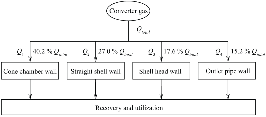
Figure 18: The distributions of heat transfer rate proportions on the walls of the circumfluent cyclone separator
The heat transfer rate proportions distributions obtained above are significant for on-site operation. According to the distributions of heat transfer rate proportions, the regions with strong or poor heat transfer on the wall of the circumfluent cyclone separator can be predicted during the actual converter gas recovery process. This prediction enables the reasonable arrangement of the evaporation heating surface based on regions with different heat transfer intensities. By optimizing the arrangement, the recovery and utilization of sensible heat from converter gas can be maximized, and the potential safety hazards caused by evaporation overheating can be prevented.
Based on on-site operation tests, the distributions of the converter gas flow and wall heat transfer in the circumfluent cyclone separator are studied by numerical simulation. The following conclusions are drawn:
(1) The gas flow rate proportions in the different regions of the circumfluent cyclone separator remain constant during the steelmaking process, they are not affected by the inlet conditions but rather by the structure of the separator.
(2) The distributions of flow rate proportions in the circumfluent cyclone separator are revealed. When the converter gas enters the inner chamber, 80.1% of the gas flows into the cone chamber. When the gas flows out of the inner chamber, 15.4% of the gas flows into the annular chamber.
(3) The heat transfer rate proportions on the walls of different regions in the circumfluent cyclone separator remain constant during the steelmaking process.
(4) The distributions of heat transfer rate proportions on the circumfluent cyclone separator walls are obtained. The proportions of heat transfer rate on walls of the cone chamber, straight shell, shell head and outlet pipe are 40.2%, 27.0%, 17.6% and 15.2%, respectively.
The present work is the first step in the study of circumfluent cyclone separators for converter gas dust removal and sensible heat recovery, and the research results reveal the distribution laws of internal flow and wall heat transfer during the steelmaking process. According to the distribution laws, the circumfluent cyclone structure can be optimized to improve dust removal and heat transfer performance. Furthermore, the distribution laws provide a reference for the reasonable arrangement of the evaporation heating surface on the separator wall surface. The limitation of this study is that it only provides the theoretical basis and guidance for improving the dust removal and heat transfer performance of the circumfluent cyclone separator, without specific measures for improving the performance and the effects of these measures. In future research, we plan to optimize the circumfluent cyclone structure based on the results of this study to improve dust removal and heat transfer performance, and evaluate the effects through experimental and numerical methods.
In addition, many industrial facilities, such as coal-fired boilers, cement kilns and waste incinerators, need to solve the problems of high temperature flue gas dust removal and waste heat recovery. The results obtained in this study provide a basis for the application of circumfluent cyclone separator with heat transfer function in these facilities.
Acknowledgement: The author, Ziyi Wang, acknowledges the Institute of Mechanics, Chinese Academy of Sciences, and Baogang Group for providing the necessary support.
Funding Statement: This research was funded by the Strategic Priority Research Program of the Chinese Academy of Sciences, Grant Number XDA29020503.
Author Contributions: Study conception and design: Ziyi Wang, Sen Li, Xiaolin Wei; Data collection: Jing Zhao, Bo Li, Yuan Yao; Analysis and interpretation of results: Ziyi Wang, Sen Li; Draft manuscript preparation: Ziyi Wang, Sen Li. All authors reviewed the results and approved the final version of the manuscript.
Availability of Data and Materials: The data that support the findings of this study are available from the corresponding author, Sen Li, upon reasonable request.
Ethics Approval: Not applicable.
Conflicts of Interest: The authors declare no conflicts of interest to report regarding the present study.
References
1. Aleksashin L, Schnaltzger I, Hollias G. Creation and growth of oxygen-converter steelmaking. Metallurgist. 2007;51(1):60–5. doi:10.1007/s11015-007-0014-4. [Google Scholar] [CrossRef]
2. Li S, Wei XL, Yu LX. Numerical simulation of gas formation during top-blown oxygen converter steelmaking. Fuel. 2011;90(4):1350–60. doi:10.1016/j.fuel.2011.01.022. [Google Scholar] [CrossRef]
3. Milosevic H, Stevovic S, Petkovic D. Numerical simulation of interaction during the top blow in a steel-making converter. Int J Heat Mass Transf. 2011;54(19–20):4275–9. doi:10.1016/j.ijheatmasstransfer.2011.05.018. [Google Scholar] [CrossRef]
4. Li Z, Zhu R, Ma G, Wang X. Laboratory investigation into reduction the production of dust in basic oxygen steelmaking. Ironmak Steelmak. 2017;44(8):601–8. doi:10.1080/03019233.2016.1223906. [Google Scholar] [CrossRef]
5. Zhou Y, Zhu R, Wei GS. Recent advancements in source reduction and recycling technologies for converter dust. Energy Rep. 2022;8(3):7274–85. doi:10.1016/j.egyr.2022.05.234. [Google Scholar] [CrossRef]
6. Zhai YH, Li S, Yan WP, Wei XL, Zhang LY, Wang YT. Effects of water vapor and temperature on NOx and CO emissions during converter gas combustion. Fuel. 2019;256(4):115914. doi:10.1016/j.fuel.2019.115914. [Google Scholar] [CrossRef]
7. Zhao J, Li B, Wei XL, Li T, Li S. New green and low-carbon technology for all-sensible heat recovery of converter gas. J Clean Prod. 2024;438:140699. doi:10.1016/j.jclepro.2024.140699. [Google Scholar] [CrossRef]
8. Duan JH, Gao S, Lu YC, Wang WW, Zhang P, Li CJ. Study and optimization of flow field in a novel cyclone separator with inner cylinder. Adv Powder Technol. 2020;31(10):4166–79. doi:10.1016/j.apt.2020.08.020. [Google Scholar] [CrossRef]
9. Hwang IS, Jeong HJ, Hwang J. Effects of vortex finder length on flow field and collection efficiency of cyclone in an industrial-scale circulating fluidized bed boiler: numerical study. Int J Energy Res. 2020;44(9):7229–41. doi:10.1002/er.5430. [Google Scholar] [CrossRef]
10. Fushimi C, Yato K, Sakai M, Kawano T, Kita T. Recent progress in efficient gas-solid cyclone separators with a high solids loading for large-scale fluidized beds. KONA Powd Partic J. 2021;38:94–109. doi:10.14356/kona.2021001. [Google Scholar] [CrossRef]
11. Li S, Shen Y. CFD investigation of maldistribution in a full-loop circulating fluidized bed with double parallel cyclones. Powder Technol. 2021;381:665–84. doi:10.1016/j.powtec.2020.12.020. [Google Scholar] [CrossRef]
12. Venkatesh S, Sivapirakasam SP, Sakthivel M, Ganeshkumar S, Mahendhira Prabhu M, Naveenkumar M. Experimental and numerical investigation in the series arrangement square cyclone separator. Powder Technol. 2021;383:93–103. doi:10.1016/j.powtec.2021.01.031. [Google Scholar] [CrossRef]
13. Karagoz I, Kaya F. CFD investigation of the flow and heat transfer characteristics in a tangential inlet cyclone. Int Commun Heat Mass Transf. 2007;34(9–10):1119–26. doi:10.1016/j.icheatmasstransfer.2007.05.017. [Google Scholar] [CrossRef]
14. Nag PK, Gupta AVSSKS. Fin heat transfer studies in the cyclone separator of a circulating fluidized bed. Heat Transf Eng. 1999;20(2):28–34. doi:10.1080/014576399271556. [Google Scholar] [CrossRef]
15. Dasar M, Patil RS. Studies on separation efficiency and energy conservation through novel finned cyclone separator. J Heat Transf. 2020;142(4):042104. doi:10.1115/1.4046303. [Google Scholar] [CrossRef]
16. Yohana E, Tauviqirrahman M, Laksono DA, Charles H, Choi K-H, Yulianto ME. Innovation of vortex finder geometry (tapered in-cylinder out) and additional cooling of body cyclone on velocity flow field, performance, and heat transfer of cyclone separator. Powder Technol. 2022;399(7):117235. doi:10.1016/j.powtec.2022.117235. [Google Scholar] [CrossRef]
17. Liu X, Wen Z, Su F, Du Y, Zhang S, Lou G. Simulation of motion and heat transfer characteristics of blast-furnace slag particles in a cyclone separator. Iran J Sci Technol Transact Mechan Eng. 2024;48(4):2131–42. doi:10.1007/s40997-024-00768-9. [Google Scholar] [CrossRef]
18. Wang WW, Zhang P, Wang LX, Chen GH, Li JL, Li XG. Structure and performance of the circumfluent cyclone. Powder Technol. 2010;200(3):158–63. doi:10.1016/j.powtec.2010.02.020. [Google Scholar] [CrossRef]
19. Duan JH, Guan XX. Numerical simulation of the influence of outer chamber height on flow field in circumfluent cyclone separator. Adv Mater Res. 2013;694–697:555–9. doi:10.4028/www.scientific.net/AMR.694-697.555. [Google Scholar] [CrossRef]
20. Zhang P, Chen G, Duan J, Wang W. Experimental evaluation of separation performance of fine particles of circulatory circumfluent cyclone separator system. Sep Purif Technol. 2019;210:231–5. doi:10.1016/j.seppur.2018.08.008. [Google Scholar] [CrossRef]
21. Wang HG, Liu S. Application and comparison of different turbulence models in the three-dimensional numerical simulation of cyclone separators. J Eng Therm Ener Pow. 2003;18(4):337–42 (In Chinese). [Google Scholar]
22. Tao WQ. Heat transfer. 5th ed. China: Higher Education Press; 2019. p. 538–41(In Chinese). [Google Scholar]
23. Chen B, Lu YJ, Li WY, Dai XY, Hua X, Xu JH, et al. DPM-LES investigation on flow field dynamic and acoustic characteristics of a twin-fluid nozzle by multi-field coupling method. Int J Heat Mass Transf. 2022;192(1):122927. doi:10.1016/j.ijheatmasstransfer.2022.122927. [Google Scholar] [CrossRef]
24. Zhou RR, Li BW. The modified discrete ordinates method for radiative heat transfer in two-dimensional cylindrical medium. Int J Heat Mass Transf. 2019;139:1018–30. doi:10.1016/j.ijheatmasstransfer.2019.05.071. [Google Scholar] [CrossRef]
25. Wei YJ, Liu XC, Zhu KY, Huang Y. A unified lattice Boltzmann framework for combined radiation-conduction heat transfer. Int J Heat Mass Transf. 2023;200(1):123513. doi:10.1016/j.ijheatmasstransfer.2022.123513. [Google Scholar] [CrossRef]
26. Taler D, Taler J. Simplified analysis of radiation heat exchange in boiler superheaters. Heat Transf Eng. 2009;30(8):661–9. doi:10.1080/01457630802659953. [Google Scholar] [CrossRef]
27. Zheng S, Qi CB, Huang ZF, Zhou HC. Non-gray radiation study of gas and soot mixtures in one-dimensional planar layer by DRESOR. J Quant Spectrosc Radiat Transf. 2018;217:425–31. doi:10.1016/j.jqsrt.2018.06.020. [Google Scholar] [CrossRef]
28. Kang SH, Yoo CS. A modification of the narrow band-based WSGG regrouping method for computation time reduction in non-gray gas radiation analysis. Int J Heat Mass Transf. 2017;111(3):1314–21. doi:10.1016/j.ijheatmasstransfer.2017.04.091. [Google Scholar] [CrossRef]
29. da Fonseca RJC, Fraga GC, Coelho FR, França FHR. A wide-band based weighted-sum-of-gray-gases model for participating media: application to H2O-CO2 mixtures with or without soot. Int J Heat Mass Transf. 2023;204(15):123839. doi:10.1016/j.ijheatmasstransfer.2022.123839. [Google Scholar] [CrossRef]
30. Yin G. On gas and particle radiation in pulverized fuel combustion furnaces. Appl Energy. 2015;157:554–61. doi:10.1016/j.apenergy.2015.01.142. [Google Scholar] [CrossRef]
31. Li S, Wei XL. Numerical simulation of CO and NO emissions during converter gas combustion in the cooling stack. Combust Sci Technol. 2013;185(2):212–25. doi:10.1080/00102202.2012.715606. [Google Scholar] [CrossRef]
32. Hoffmann AC, Stein LE. Cyclone separators: principles, design, and engineering applications. Germany: Springer; 2008. p. 26. [Google Scholar]
Cite This Article
 Copyright © 2025 The Author(s). Published by Tech Science Press.
This work is licensed under a Creative Commons Attribution 4.0 International License , which permits unrestricted use, distribution, and reproduction in any medium, provided the original work is properly cited.
 Downloads
 Citation Tools