 Open Access
ARTICLE
Contact Melting in an Elliptical Tube under the Second Kind of Thermal Boundary Condition
College of Nuclear Science and Technology, Naval University of Engineering, Wuhan, 430033, China
* Corresponding Author: Junjie Ma. Email:
Frontiers in Heat and Mass Transfer 2024, 22(6), 1823-1837. https://doi.org/10.32604/fhmt.2024.057896
Received 30 August 2024; Accepted 17 October 2024; Issue published 19 December 2024
Abstract
The contact melting process of solid phase change material (PCM) has essential applications in some energy storage systems, which is related closely to the heat resource’s geometry and thermal boundary conditions. The contact melting of PCM in a horizontal elliptical tube under the second kind of thermal boundary condition, namely the constant surface heat flux, was investigated analytically. The analysis model is proposed based on the contact melting lubrication theory, and the model deduces the basic dimensionless equations. The variation rules of parameters such as contact melting speed, melting completion time, and boundary layer thickness distribution are obtained for the different heat fluxes. The influences of the elliptical heat resource geometry boundary and the compression coefficient on these melting parameters were also analyzed. The results include the contact melting inside a horizontal circular tube. Compared with the contact melting under the first kind of thermal boundary condition, the constant surface temperature, some significant conclusions are drawn.Keywords
Nomenclature
| Melting height | |
| The falling speed of solid PCM | |
| Heat flux | |
| a | Major axis of ellipse |
| b | Minor axis of ellipse |
| u | Tangential velocity |
| v | Normal velocity |
| p | Liquid pressure |
| V | Solid melting rate |
| g | Gravitational acceleration |
| Liquid film thickness | |
| Density | |
| Dynamic viscosity | |
| Liquid thermal diffusivity | |
| Coefficient of thermal conductivity | |
| Pr | Prandtl number |
| Ar | Archimedes number |
| Fo | Fourier number |
| Lm | Latent heat of fusion |
| Tw | The temperature of the heat wall |
| * | Dimensionless parameter |
Contact melting occurs when solid phase change materials (PCM) and heat sources come into direct contact and exert pressure on each other, provided that the temperature of the heat source is higher than the melting point of the PCM [1]. The research indicates that under identical operating conditions, contact melting exhibits a melting rate that is 1–7 times greater than that of non-contact or constrained melting [2]. Contact melting has wide applications in various engineering and natural contexts, including melting ice and snow, storing heat energy, welding, geological exploration, and nuclear safety [3]. It is considered a highly efficient melting method and has garnered the interest of numerous scholars [4].
In recent years, the utilization of phase change materials (PCM) for latent heat thermal energy storage (LHTES) has garnered significant attention, particularly in solar-powered energy systems. For solar energy systems requiring substantial heat transfer, implementing a latent thermal energy storage system (LTES) utilizing phase change materials presents a practical and economical approach [5]. Phase change materials achieve energy storage by absorbing heat and melting. Therefore, the melting efficiency determines the effective performance of the latent heat energy storage system. The experimental results indicate that contact melting significantly enhances heat transfer during the melting process and increases melting efficiency [6]. Contact melting is intricately linked to both geometric and thermal boundary conditions. The geometric conditions encompass the shape of the heat source and the configuration of the solid material. In contrast, the thermal conditions concerning how the heat source warms the PCM and the temperature distribution across the source’s surface. Over the past four decades, numerous investigations into contact melting have been conducted [7–10]. In particular, the research on contact melting driven by temperature difference, called ΔT-driven melting, is extensive and in-depth. For example, in 1980, Nicholas and Bayazitoglu first conducted numerical analysis and experimental research on contact melting of free solids in horizontal circular tubes and obtained the flow and temperature fields in the melt liquid area and the solid shape change [11]. Subsequently, Bareiss et al. [12], Riviere et al. [13], Webb et al. [14] further carried out theoretical and experimental studies on contact melting in horizontal circular tubes and determined the flow and temperature field distribution in the melt liquid film as well as the change rule of solid volume. Hirata et al. [15] and Lacroix [16] respectively analyzed the contact melting in the rectangular cavity and established a three-dimensional analysis model. Wilchinsky et al. [17] used the analytical methods of Bareiss et al. [12] to discuss contact melting in plastic containers. Aljaghtham et al. [6] conducted a study to explore how slip velocity and temperature affect the contact melting process of an electrically conductive PCM when exposed to a magnetic field. A comprehensive analytical solution has been devised for thin film flow and energy transport, incorporating unsteady phase change heat transfer under Navier slip conditions. This solution also accounts for interactions with electromagnetic fields, which are defined by Maxwell’s equations. Fu et al. utilized pressure-enhanced close-contact melting as a means to maintain elevated energy and power densities [9]. A decrease in the performance of thermal energy storage systems based on phase change materials was observed as the melt front progressed further away from the heat source. The research above adopted the analysis model under the condition of an isothermal heat source, which belongs to the first kind of thermal boundary condition. It can be seen from the analysis results that melting speed, liquid film thickness distribution, and other parameters are expressed as a function of temperature difference or Stefan number, so this analysis model is called the temperature difference contact melting model. In recent years, the application of phase change materials (PCM) for latent heat thermal energy storage (LHTES) has garnered significant interest. Experimental results have shown that contact melting notably improves heat transfer efficiency during the melting process [18]. However, in the energy storage system, the constant heat flux boundary condition is easier to control and implement compared to the constant temperature boundary condition. The PCM in the heat storage element absorbs heat and melts, the heat flux on the surface of the component is steady, and the surface temperature is not uniform [19], which belongs to the melting under the second kind of thermal boundary condition and is different from that under the first kind of thermal boundary condition. Studies on contact melting within a container subjected to a constant heat flux are relatively scarce. Elliptical cross-sections demonstrate excellent performance in structural mechanics, particularly when subjected to axial compressive loads [20]. Compared to circular cross-sections, elliptical cross-sections exhibit superior mechanical properties and stability [21]. This advantage endows elliptical cross-sections with potential application prospects in energy storage structure designs that demand high strength and stability [2]. Furthermore, due to their high thermal conductivity and significant engineering applications, several researchers have examined the contact melting processes occurring both around and within heat sources with elliptical geometries. In the present work, the contact melting process of phase change material in a horizontal elliptical tube under the second kind of boundary condition is analyzed.
The physical model of the problem under consideration is shown in Fig. 1, where the elliptical tube section satisfies the equation
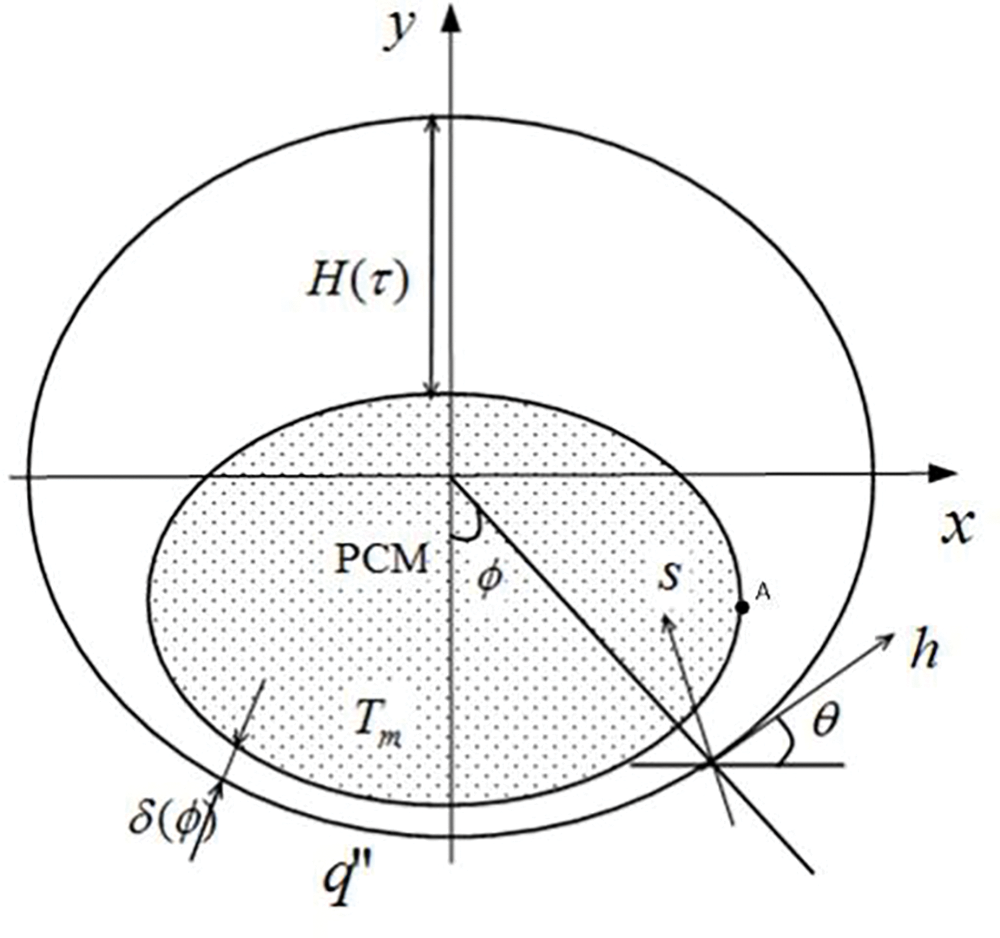
Figure 1: Physical model and coordinates of constant heat flux melting in elliptical tubes
According to the above assumptions, the governing equations of the flow in the molten liquid film, namely the continuity, momentum and energy equations are simplified as follows:
By analyzing the temperature distribution in the liquid film, it is found that the tangential (along direction h) temperature gradient is much smaller than the vertical temperature gradient (along direction s), namely
The temperature boundary condition of liquid film layer is:
Using the boundary condition Eq. (5), the differential Eq. (4) was solved to obtain the liquid film temperature distribution as follows:
The energy balance equation at the solid-liquid contact melting interface is:
Substituting the derivative of Eq. (6) with respect to s into Eq. (7), the liquid film thickness distribution can be obtained as follows:
The boundary conditions of liquid flow velocity are:
Using the boundary condition Eq. (9), the momentum Eq. (2) is twice integrated along s to obtain u as follows:
The mass conservation equation of melting process is:
Substituting Eq. (10) into Eq. (11), the tangential pressure in the molten liquid film can be written as:
The force balance equation of solid in the melting process is:
According to Fig. 1, the following geometric relationship exists:
where,
The relation between the angles
The relation between the boundary angle
The residual solid volume
Substituting Eqs.(14) and (17) into Eqs. (12) and (13) results in:
Introduce the following dimensionless parameters:
Substituting the dimensionless quantities above into Eqs. (8), (18) and (19) yields:
Eqs. (20)–(22) are dimensionless equations of constant heat flux contact melting of phase change material in an elliptical tube heat source, where the independent variable is the height
When the compression coefficient J is equal to 1,
Eqs. (23)–(25) are the analytical results of the solid contact melting process in the horizontal circular tube [26].
In this paper, n-octadecane is chosen as the PCM material for calculation and discussion. The thermophysical properties of PCM are Tm = 28°C,
Fig. 2 shows the change curve of solid PCM’s falling speed
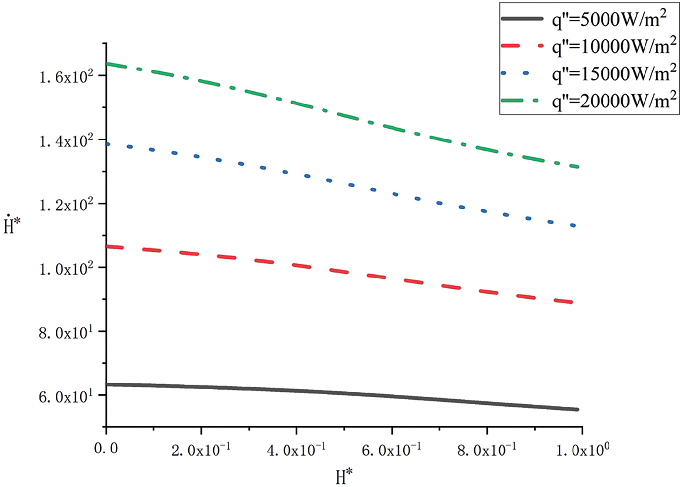
Figure 2: Variation of
The relationship between dimensionless the solid melting rate
The dimensionless melting time
The variation curve of the solid melting rate
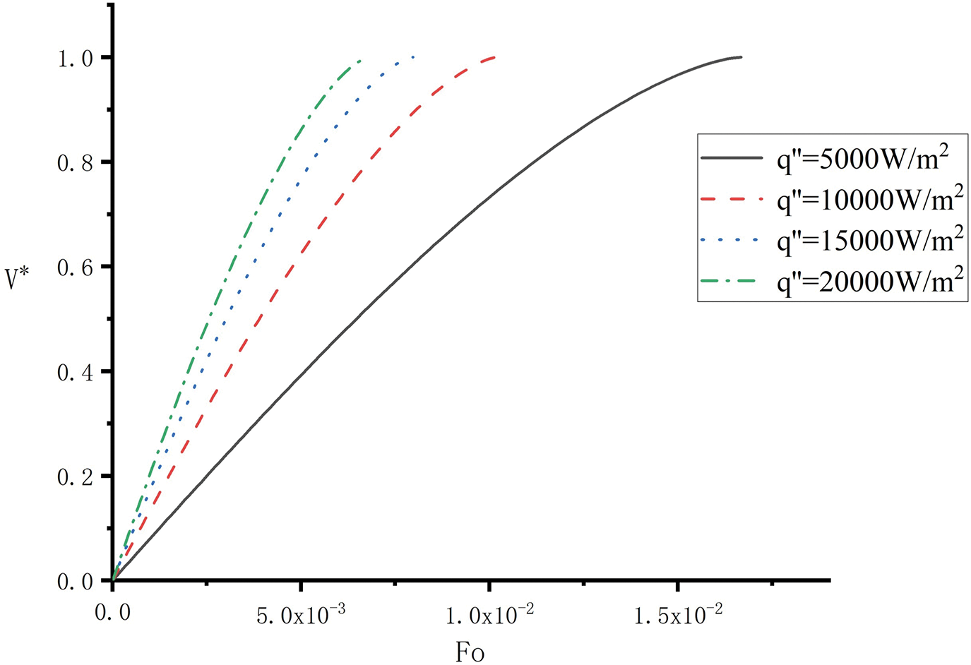
Figure 3: Variation of
The variation of the liquid film thickness
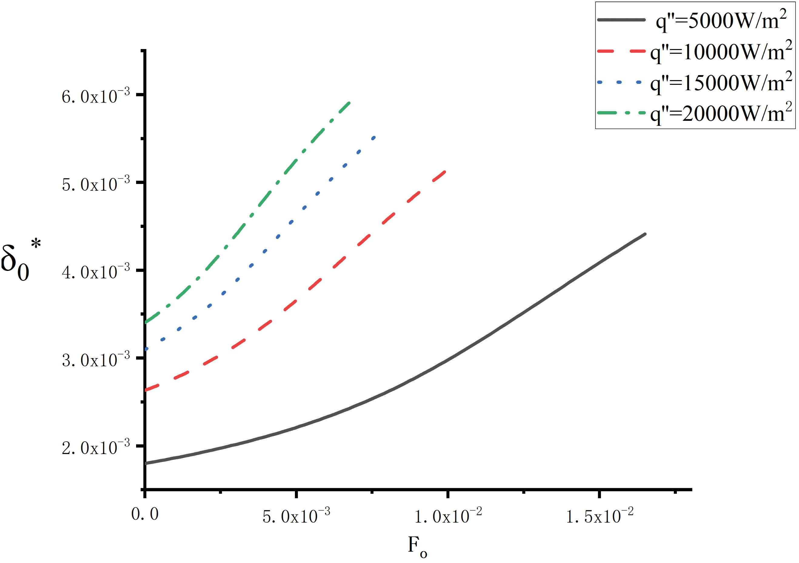
Figure 4: Variation of
To evaluate the effect of the elliptical shape on the melting, Fig. 5 shows the variation of the falling velocity
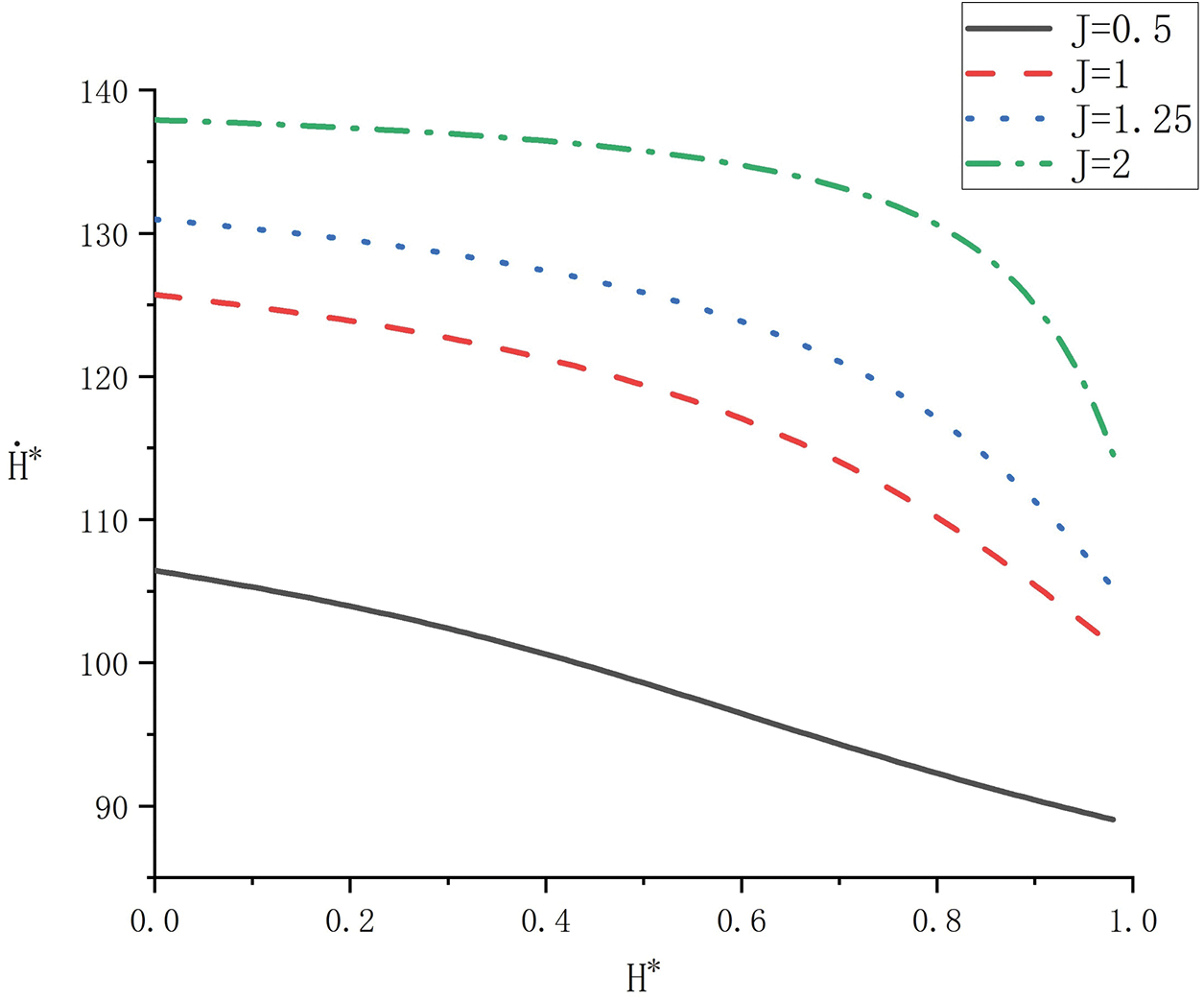
Figure 5: Variation of
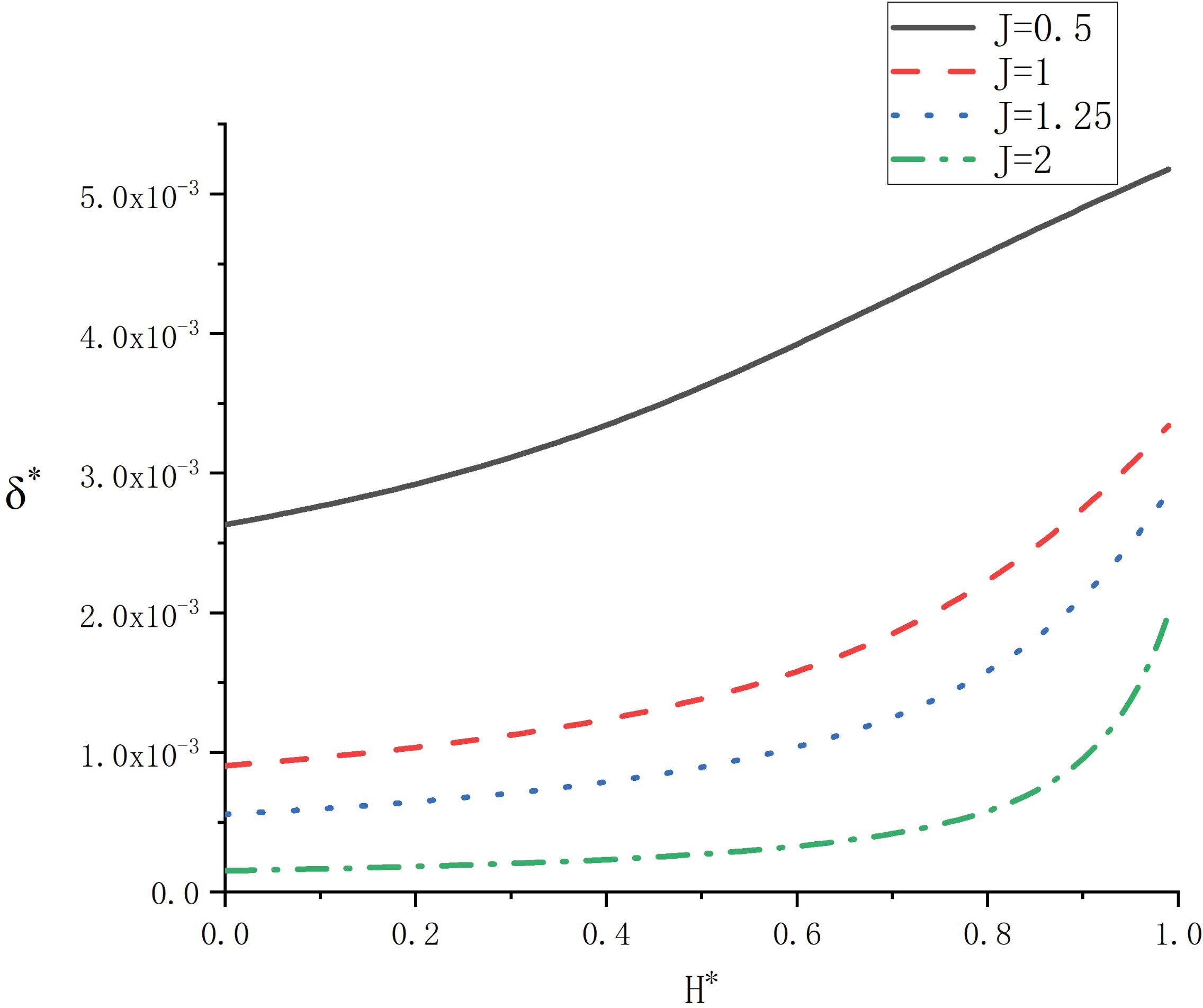
Figure 6: Variation of
The influence of heat source shape on melting rate was analyzed for the same solid volume at
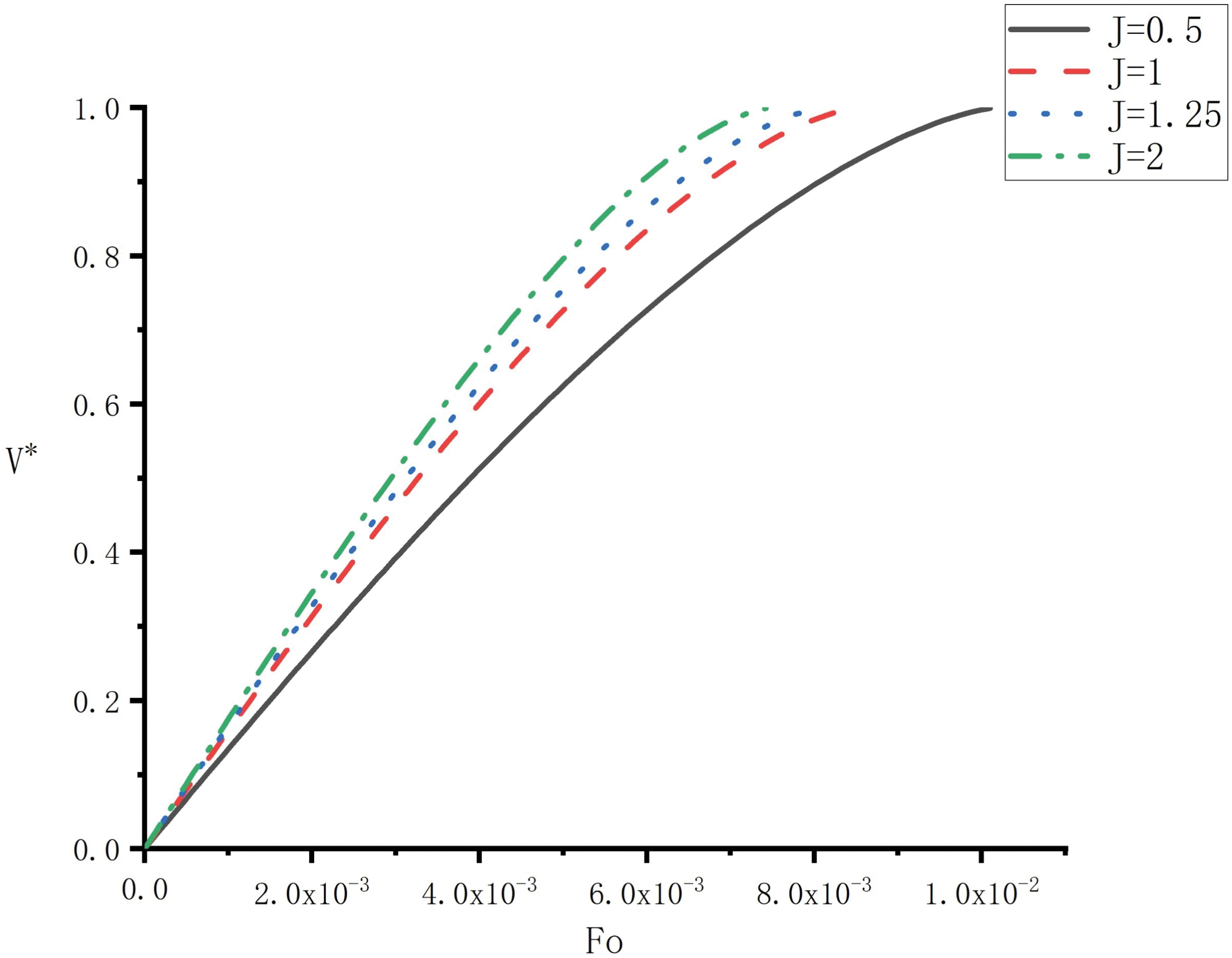
Figure 7: Influence of heat source shape on melting rate
Fig. 8 illustrates the impact of J on the dimensionless parameters of the temperature
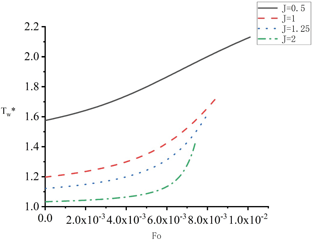
Figure 8: Influence of heat source shape on heat wall temperature
Fig. 9 compares the variation of the complete melting times
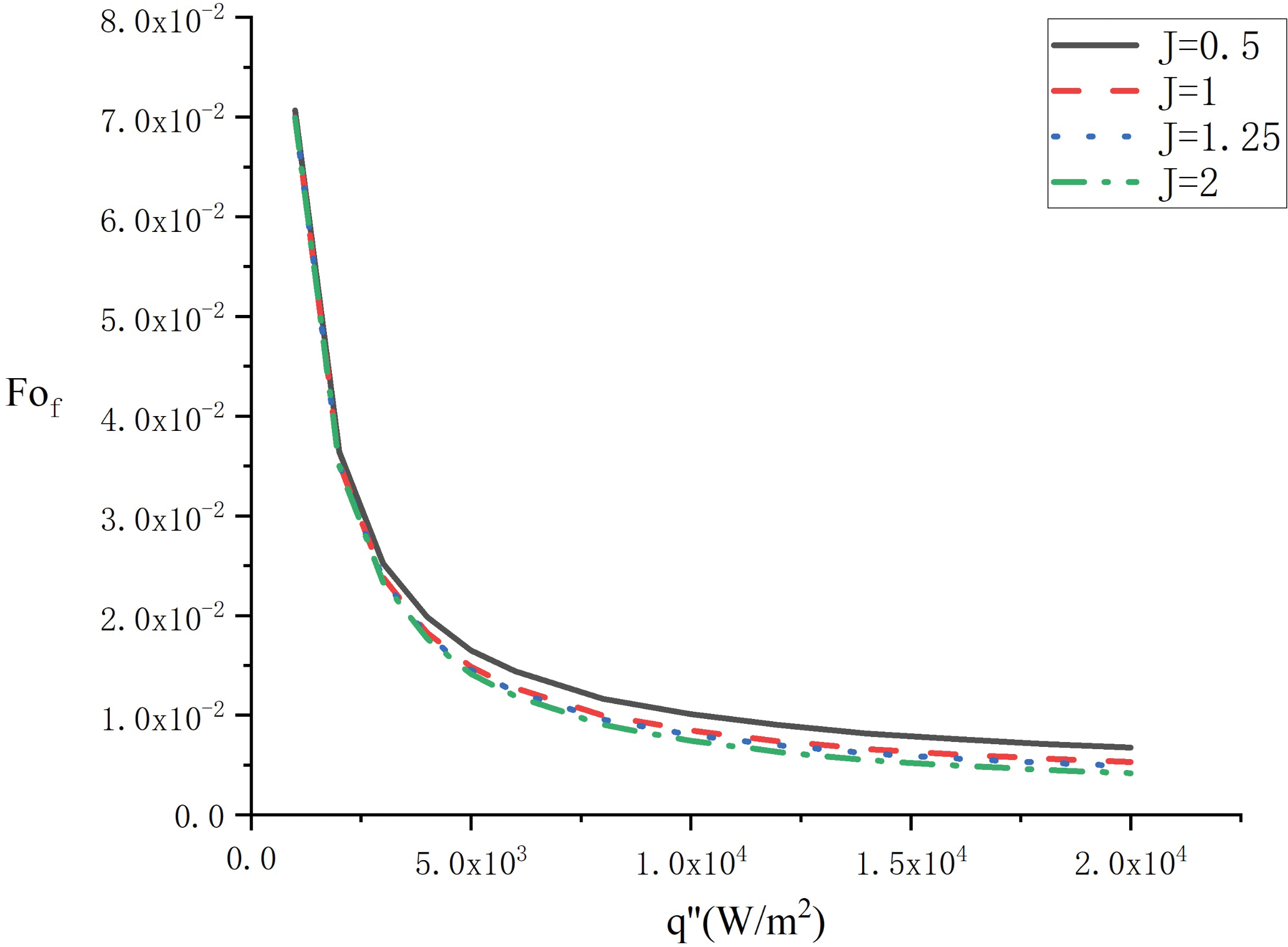
Figure 9: Variation of the elapsed time with heat flux
It is shown from Fig. 10 that the completed melting time for constant heat flux melting is longer than that for constant temperature melting which calculated by Reference [21] under the condition of the same heat flux, so the heat transfer efficiency of constant heat flux melting is lower than that of constant temperature melting. Under conditions of low heat flux, the melting efficiency of constant temperature melting is significantly higher than that of constant heat flux. Nevertheless, under conditions of high heat flux, the disparity in melting time between constant temperature and constant heat flux conditions is minimal. Consequently, an energy storage heating method that is more easily attainable can be chosen depending on the specific energy storage conditions.
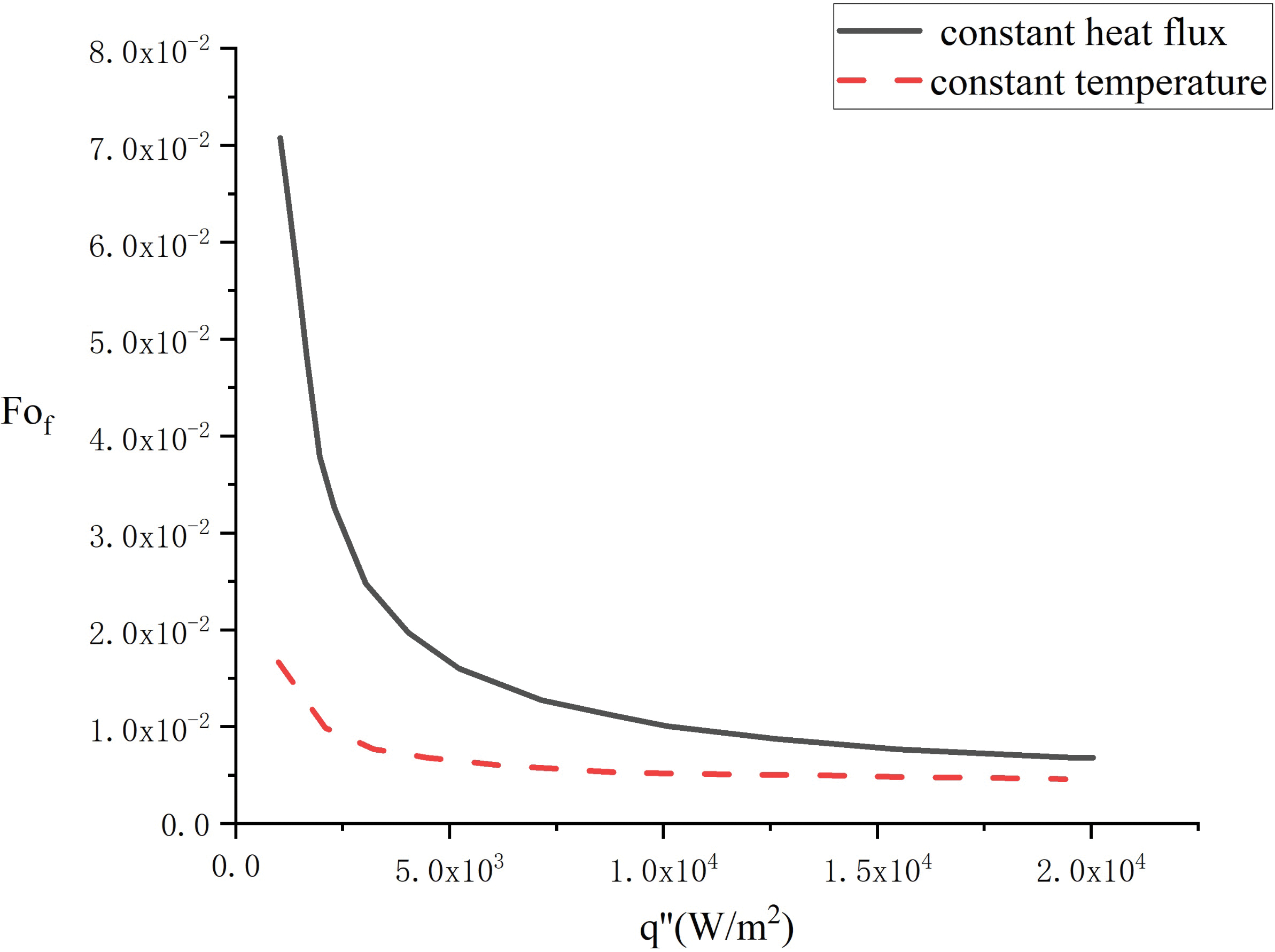
Figure 10: Comparison of the elapsed time of first and second thermal boundary conditions
The contact melting of solid PCM in a horizontal elliptical tube with constant heat flux is analyzed. The control equations of melting are established by the Nusselt theory. Through theoretical derivation, the dimensionless equations describing the contact melting process are obtained and solved using the numerical method. This paper chooses n-octadecane as the PCM material for calculation and discussion. The variations of melting parameters such as falling speed, melting rate, solid height, and liquid film distribution under different heat fluxes from heat sources were derived and discussed. The results are applicable to phase change heat transfer problems under the second kind of thermal boundary condition. The following conclusions were drawn:
(1) During the contact melting of solid PCM in elliptical tubes, the thickness of contact melting liquid film increases gradually with the decrease of solid height, which reduces the melting speed.
(2) The increase in heat flux reduces the time required for complete melting of the PCM. And under low heat flux conditions, increasing the heat flux will more effective in improving the melting efficiency.
(3) At the same heat flux, the higher the ellipse compression coefficient J, the higher the falling speed
(4) Under conditions of low heat flux, the melting efficiency of constant temperature melting is significantly higher than that of constant heat flux. However, under high heat flux conditions, the difference in melting time between constant temperature and constant heat flux conditions is relatively small, so a more easily achievable energy storage heating method can be selected based on the energy storage conditions.
Acknowledgement: The authors deeply grateful to supervisor and peers for their invaluable guidance and support.
Funding Statement: This research was financially supported by the National Natural Science Foundation of China (Project number 12175311).
Author Contributions: The authors confirm contribution to the paper as follows: study conception and design: Wenzhen Chen; data collection: Junjie Ma; analysis and interpretation of results: Wenzhen Chen, Junjie Ma, Jianli Hao; draft manuscript preparation: Wenzhen Chen, Junjie Ma. All authors reviewed the results and approved the final version of the manuscript.
Availability of Data and Materials: The data that support the findings of this study are available from the corresponding author, Junjie Ma, upon reasonable request.
Ethics Approval: Not applicable.
Conflicts of Interest: The authors declare no conflicts of interest to report regarding the present study.
References
1. Bejan A. Contact melting heat transfer and lubrication. Adv Heat Transfer. 1994;24:1–28. doi:10.1016/S0065-2717(08)70231-4. [Google Scholar] [CrossRef]
2. Chen WZ. Analysis of contact melting. Beijing: Chinese Atomic Energy Press; 2022 (In Chinese). [Google Scholar]
3. Chen WZ, Ma JJ, Xiao HG. Study on contact melting process of vertical cylindrical materials in a circular container. Prog Nucl Energy. 2023;166:104974. doi:10.1016/j.pnucene.2023.104974. [Google Scholar] [CrossRef]
4. Hu N, Lia ZR, Xua ZW, Fan LW. Rapid charging for latent heat thermal energy storage: a state-of-the-art review of close-contact melting. Renew Sustain Energy Rev. 2022;155:111918. doi:10.1016/j.rser.2021.111918. [Google Scholar] [CrossRef]
5. Abolfazl N, Marcello I, Giuseppe L, Nicola B. Thermal enhancement techniques for a lobed-double pipe PCM thermal storage system. Appl Therm Eng. 2023;233:121139. doi:10.1016/j.applthermaleng.2023.121139. [Google Scholar] [CrossRef]
6. Aljaghtham M, Premnath K, Alsulami R. Investigation of time-dependent microscale close contact melting. Int J Heat Mass Transfer. 2021;166:120742. doi:10.1016/j.ijheatmasstransfer.2020.120742. [Google Scholar] [CrossRef]
7. Myers TG, Mitchell SL, Muchatibaya G. Unsteady contact melting of a rectangular cross-section material on a flat plate. Phys Fluids. 2008;20(10):103101. doi:10.1063/1.2990751. [Google Scholar] [CrossRef]
8. Cregan V, Williams J, Myers TG. Contact melting of a rectangular block with temperature-dependent properties. Int J Therm Sci. 2020;150(2):106218. doi:10.1016/j.ijthermalsci.2019.106218. [Google Scholar] [CrossRef]
9. Fu W, Yan X, Gurumukhi Y, Garimella VS, King WP, Miljkovic N. High power and energy density dynamic phase change materials using pressure-enhanced close contact melting. Nat Energy. 2022;7(3):270–80. doi:10.1038/s41560-022-00986-y. [Google Scholar] [CrossRef]
10. Ma JJ, Chen WZ, Xiao HG. Study of contact melting of plate bundles by molten material in severe reactor accidents. Nucl Eng Technol. 2023;55(11):4266–73. doi:10.1016/j.net.2023.08.003. [Google Scholar] [CrossRef]
11. Nicholas D, Bayazitoglu Y. Heat transfer and melting front within a horizontal cylinder. J Sol Energy Eng. 1980;102(3):229–32. doi:10.1115/1.3266160. [Google Scholar] [CrossRef]
12. Bareiss M, Beer H. An analytical solution of the heat transfer process during melting of an unfixed solid phase change material inside a horizontal tube. Int J Heat Mass Transfer. 1984;27(5):739–46. doi:10.1016/0017-9310(84)90143-1. [Google Scholar] [CrossRef]
13. Riviere P, Beer H. Experimental investigation of melting of unfixed ice in an isothermal horizontal cylinder. Int Commun Heat Mass Transfer. 1987;14(2):155–65. doi:10.1016/S0735-1933(87)81006-0. [Google Scholar] [CrossRef]
14. Webb BW, Moallemi MK, Viskanta R. Experiments of melting unfixed ice in a horizontal cylindrical capsule. ASME J Heat Transfer. 1987;109(2):454–9. doi:10.1115/1.3248103. [Google Scholar] [CrossRef]
15. Hirata T, Makino Y, Kaneko Y. Analysis of close-contact melting for octadecane and ice inside isothermally heated horizontal rectangular capsule. Int J Heat Mass Transfer. 1995;34(12):3097–106. doi:10.1016/0017-9310(91)90079-T. [Google Scholar] [CrossRef]
16. Lacroix M. Contact melting of a phase change material inside a heated parallelepedic capsule. Energy Convers Manage. 2001;42(1):35–47. doi:10.1016/S0196-8904(00)00047-9. [Google Scholar] [CrossRef]
17. Wilchinsky AV, Fomin SA, Hashida T. Contact melting inside an elastic capsule. Int J Heat Mass Transfer. 2002;45(20):4097–106. doi:10.1016/S0017-9310(02)00121-7. [Google Scholar] [CrossRef]
18. Shockner T, Ziskind G. Combined close-contact and convective melting in a vertical cylindrical enclosure. Int J Heat Mass Transfer. 2021;177(3):121492. doi:10.1016/j.ijheatmasstransfer.2021.121492. [Google Scholar] [CrossRef]
19. Schüller K, Kowalski J. Spatially varying heat flux driven close contact melting–a Lagrangian approach. Int J Heat Mass Transfer. 2017;115(3):1276–87. doi:10.1016/j.ijheatmasstransfer.2017.08.092. [Google Scholar] [CrossRef]
20. Ruiz-Teran AM, Gardner L. Elastic buckling of elliptical tubes. Thin-Walled Struct. 2008;46(11):1304–18. doi:10.1016/j.tws.2008.01.036. [Google Scholar] [CrossRef]
21. Chen WZ, Yang QS, Dai MQ, Cheng SM. Analytical solution of the heat transfer process during contact melting of phase change material inside a horizontal elliptical tube. Int J Energy Res. 1998;22(2):131–40. doi:10.1002/(ISSN)1099-114X. [Google Scholar] [CrossRef]
22. Schilichting H. Boundary layer theory. New York: McGrawHill Book Company; 1979. [Google Scholar]
23. Bahrami PT, Wang TG. Analysis of gravity and conduction-driven melting in a sphere. ASME J Heat Mass Transfer. 1987;109(3):806–9. doi:10.1115/1.3248166. [Google Scholar] [CrossRef]
24. Moallemi MK, Webb BW, Viskanta R. An experimental and analytical study of close contact melting. ASME J Heat Transfer. 1986;108(4):894–9. doi:10.1115/1.3247030. [Google Scholar] [CrossRef]
25. Moallemi MK, Viskanta R. Analysis of close contact melting heat transfer. Int J Heat Mass Transfer. 1986;29(6):855–67. doi:10.1016/0017-9310(86)90181-X. [Google Scholar] [CrossRef]
26. Zhao YS, Liang WH, Chen WZ. Contact melting of unfixed solid phase change material inside a cylindrical tube with constant heat flux. Chin J Comput Phys. 2011;28(4):529–34 (In Chinese). [Google Scholar]
Cite This Article
 Copyright © 2024 The Author(s). Published by Tech Science Press.
This work is licensed under a Creative Commons Attribution 4.0 International License , which permits unrestricted use, distribution, and reproduction in any medium, provided the original work is properly cited.


 Submit a Paper
 Propose a Special lssue
 View Full Text
 Download PDF
 Downloads
 Citation Tools