 Open Access
ARTICLE
Optimizing Heat Sink Performance by Replacing Fins from Solid to Porous inside Various Enclosures Filled with a Hybrid Nanofluid
1 Mechanical Engineering Department, University of Babylon, Babylon, 51001, Iraq
2 School of Engineering and Physical Sciences, Heriot Watt University, Edinburgh, EH14 4AS, UK
* Corresponding Author: Ahmed Dhafer Abdulsahib. Email:
Frontiers in Heat and Mass Transfer 2024, 22(6), 1777-1804. https://doi.org/10.32604/fhmt.2024.057209
Received 11 August 2024; Accepted 27 September 2024; Issue published 19 December 2024
Abstract
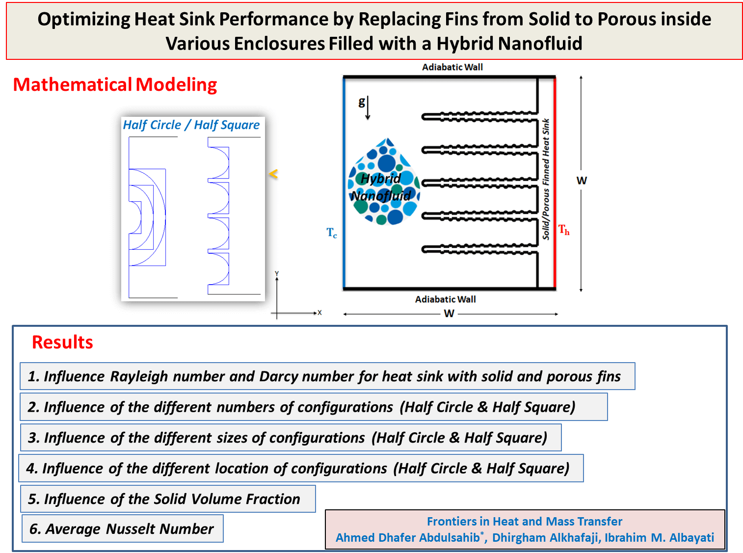
The current study generally aims to improve heat transfer in heat sinks by presenting a numerical analysis of natural convection of an enclosure with hot right and cool left walls, and thermally insulated top and bottom walls. The cold wall included configurations (half circle/half square) in various sizes (S = 0.1, 0.2, and 0.3), numbers (N = 1, 2, 3, and 4), and locations (C = 0.35, and 0.65). A heat sink is constructed of Aluminum attached to the hot wall, and composed of five fins with protrusions. Fins of the heat sink will be examined in a solid and porous structure. The enclosure is filled with a hybrid nanofluid of Nanoparticles (MWCNT and Fe3O4) and water. The current study utilized COMSOL Multiphysics software due to its efficacy in addressing scientific and technical challenges involving partial differential equations. The solving of the governing equations is achieved using the finite element method with various parameters: Rayleigh number (Ra = 103–106), Darcy number (Da = 10−2, 10−3), solid volume fraction ( = 0–0.06) to determine stream function, isotherms lines, and average Nusselt number (Nu). The results of numerical simulations show that heat sink with solid fins have a 97% higher stream function when Ra is raised from 103 to 105. Whilst with porous fin heat sink, a stream function 96% for Da = 10−3 and 94% for Da = 10−2. Changing solid fins to porous increases stream functions by 9% at Da = 10−3 and 20% at Da = 10−2. It has been found that Ra increases Nu by 44% for solid fins and 50% for porous fins. Making solid fins porous increases Nu by 54% at Ra = 106. The high increase in the percentage of (Nu) indicates the importance of the improvement in heat transfer, and this distinguishes the results of the current study from previous studies. Nu values were found highest for (half square) compared to (half circle), with 2% increases for numbers, 11.6% for sizes, and 11% for location. Solid volume fractions for all Ra at a solid-finned heat sink increased Nu by 23%.Graphic Abstract
Keywords
Nomenclature
| Ra | Rayleigh number |
| Pr | Prandtl number |
| Da | Darcy number |
| g | Acceleration by gravity, m.s−2 |
| Cp | Specific heat capacity, J.kg−1.K−1 |
| T | Temperature, K |
| U, V | Non-dimensional velocity components in X and Y directions |
| x, y | Cartesian coordinates, m |
| X, Y | Non-dimensional Cartesian coordinates |
| W | Non-dimensional length and height of the enclosure, m |
| N | Shape numbers |
| S | Shape sizes |
| L | Shape locations |
| k | Thermal conductivity, W.m−1.K−1 |
| kr | Thermal conductivity ratio, Kr = kw/kf |
| P | Non-dimensional pressure |
| K | Permeability of the porous media, m2 |
| KHs | Thermal conductivity of solid heat sink, W.m−1.K−1 |
| Greek Symbols | |
| β | Thermal expansion coefficient, K−1 |
| α | Thermal diffusivity, m2.s−1 |
| µ | Dynamic viscosity, kg. m−1.s−1 |
| Ψ | Absolute stream function |
| ɸ | Solid volume fraction |
| θ | Dimensionless temperature |
| Y | Modified conductivity ratio |
| Subscripts | |
| bf | Base fluid |
| c | Cold |
| h | Hot |
| hnf | Hybrid nanofluid |
| p | Nanoparticle |
| s | Solid |
| Hs | Solid heat sink |
The enhancement of convection heat transfer within a cavity has been reported as a focus of study by researchers and industry for various engineering applications, including solar collectors, nuclear reactors, cooling of electronic equipment, tubular heat exchangers, steel suspension cables, oil well drilling, and rotating shafts. The aim is to understand the parameters that affect heat transfer to improve these applications [1,2].
A remarkable increase in investigating free convection inside enclosures reported over the past years [3–5]. Some studies use metal nanoparticles in working fluids to increase enclosure heat transmission [6,7]. Many studies have examined how cavity inclination affects natural convection [8,9]. Yaghoubi Emami et al. [10] found that the nanofluid concentration, porous media properties, and cavity angle significantly affect heat transfer. Other researchers have investigated the effect of heated inner bodies on heat transfer inside the cavity [11–13]. Hussein [14] found that increasing Ra will increase flow circulation intensity along the circular cylinder with a hot boundary.
Many numerical studies have examined convection in a cavity filled completely or partially with porous medium with pure liquid or nanofluid [15,16]. Porous media are materials that contain pores which can lead to increased heat transfer due to the large surface area they provide. Porous media can be arranged in enclosure vertically [17,18] or horizontally [19,20]. Multiple nanofluid investigations in porous media, boundary conditions, and flow regimes were examined to compare heat transfer [21,22]. Miroshnichenko et al. [23] studied flow and heat transfer in the enclosure with two fluid and two porous media layers. Convective heat transfer through the cavity is affected significantly by porous layer height. Wavy walls improve heat exchange compared to flat walls; hence they are given special attention [24,25].
Nanoparticles are nanometer-sized particles that are effective in improving heat transfer when suspended in various fluids. They are either single, consisting of one type of particle, or hybrid, consisting of two or more nanoparticles. In general, hybrid nanoparticles offer better thermal improvements and properties than single nanoparticles. The addition of hybrid nanoparticles to the pure fluid due to combines the properties of nanoparticles and improves convective heat transfer within the cavity [26,27]. Chamkha et al. [28] explored the natural convective heat transfer of copper and alumina in a square cavity with a solid block adjacent to a porous block at the base and covered by a liquid layer. The results show that increasing the thickness of the porous solid layer reduces the circulation of the hybrid nanofluid, which reduces heat transfer. Simulations of (Ag-MgO hybrid nanofluid) free convective heat transfer in a porous square container were performed by Ghalambaz et al. [29]. They found that hybrid nanoparticles increase heat transfer and reduce the strength of flow compared to pure water. Kadhim et al. [30] calculated convective heat transfer through a cavity with sinusoidal corrugations in its constant temperature lower wall and thermally insulated upper wall partially filled with a saturated horizontal porous aqueous hybrid nanofluid. Other studies used hybrid nanofluid to study heat transfer through natural convection [31,32].
The convective heat transfer increase of Al2O3/water and Al2O3–SiO2/water hybrid nanofluid in a closed cavity has been explored by Dağdeviren et al. [33]. The results indicate that convective heat transfer is most significantly enhanced at nanoparticle volume fractions of 2% for Al2O3/water and 4% for Al2O3–SiO2/water. Pazarlıoğlu et al. [34] presented a new method for using mono/hybrid nanofluid in tubes that undergo rapid expansion. These tubes are designed with differing expansion angles and are supplied with unique capsule-type dimpled fins. The research reveals that the most effective tube design, which increases the average Nusselt number by 20.0%, is achieved by using a 45° expansion angle, capsule-type dimpled fins, and a 0.5% Ag-1.5% MgO nanofluid system.
A heat sink is a device that dissipates heat from a hot body to the environment. The absence of a heat sink leads to the failure of components in electronic devices and various mechanical systems. Heat sink improvements aim to increase thermal efficiency by improving materials, surface properties, etc. Energy consumption and electronic waste have an impact on global warming, so improving heat sinks leads to improved efficiency and thus can reduce energy consumption, which means less impact on the environment. Hatami [35] conducted a numerical analysis of heat transfer caused by natural convection in a rectangular cavity equipped with heated fins. It was discovered that the Nusselt number increased when the size of the fins was bigger. Ma et al. [36] conducted a numerical analysis of unsteady natural convection in a cavity that was differentially heated and included a fin. An analysis was conducted on the influence of the Rayleigh number and fin position on the unsteady natural convection. Gao et al. [37] discovered that the addition of fins and increasing their length lead to an augmentation in the heat transfer. Hatami et al. [38] introduced equations that describe heat transfer and temperature distribution for circular porous fins. Their main objective was to enhance the thermal efficiency of the fins by the identification of various forms. Selimefendigil et al. [39] conducted a numerical analysis to examine the impact of a thin refractory fin on mixed convection heat transfer. Abdulsahib et al. [40] investigated the natural convection in a cavity with heat sink. The results proved enhance the heat transfer when used heat sinks with varying numbers and sizes of perforated fins.
Porous media introduce resistance to fluid flow and weaken convection while enhancing conduction. Hence, employing porous fins is a highly efficient method for achieving strong convection and conduction. The literature contains numerous research studies on natural convection in fin cavities, yet there are few researches on porous fins. Also, researchers have become more interested in the usage of hybrid nanofluid in recent years due to its significance in industrial applications.
This work focused on the numerical investigation of natural convection in an enclosure. Enclosure with a hot right wall, a cold left wall, and thermally insulated upper and lower walls. Additionally, a five-fin heat sink was placed attached to a hot wall. The enclosure contains a hybrid nanofluid (Multi-walled carbon nanotube (MWCNT)/Iron (II, III) oxide (Fe3O4) with water as the base fluid). MWCNT has high thermal conductivity and can withstand high temperatures, while Fe3O4 has good oxidation resistance and is also useful in controlling fluid flow in addition to its low cost. The fins are composed of solid aluminum and include protrusions on their surface. The solid fins are replaced with porous fins structure and their impact on the heat transfer will be examined. Subsequently, the cold wall will be manufactured into several configurations (half-circular/half-square) with varying sizes, numbers, and locations to get optimal heat transfer. The study also examined the impact of several parameters, such as Rayleigh and Darcy numbers, as well as the solid volume fractions of the hybrid nanofluid, on streamlines, isotherms, and the average Nusselt number.
The usage of heat sinks with porous fins comparison to solid fins offers advantages such as reduced weight and pressure loss. Additionally, porous fins provide a larger solid-liquid contact surface. Furthermore, the significance of heat transfer efficiency while utilizing a hybrid nanofluid in comparison to a conventional nanofluid. So this research will contribute to this field of research by providing results that may apply to various industrial applications. Fig. 1 shows the flowchart of this research paper from the mathematical modeling, results, and conclusions.
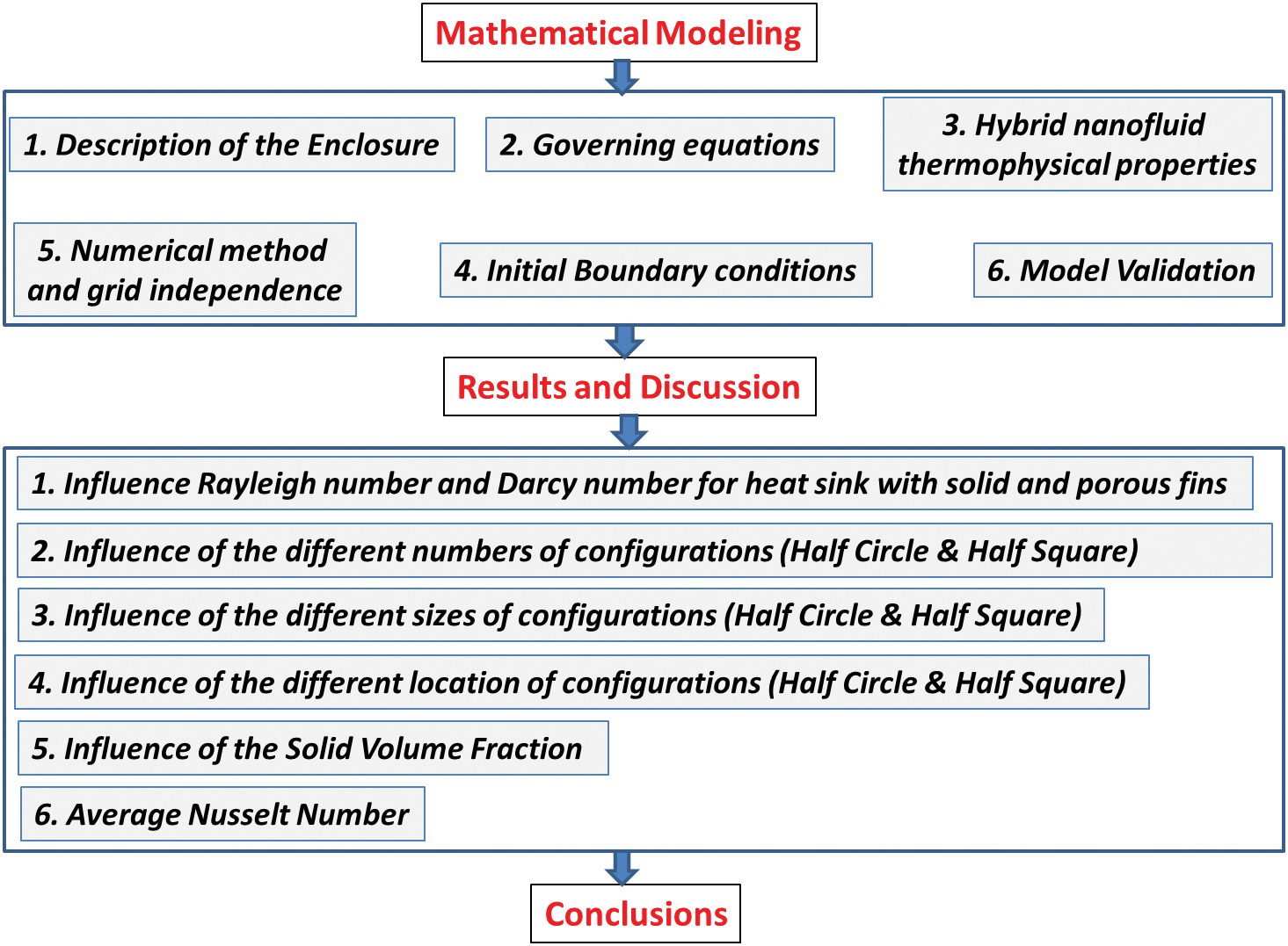
Figure 1: Flowchart for current study
2.1 Description of the Enclosure
The research was conducted using a square cavity that had a length of (W), with the right wall being hot (Th) and the left side being cold (Tc). The cold wall included (half circle/half square) in various sizes of (S = 0.1, 0.2, and 0.3), numbers (N = 1, 2, 3, and 4), and locations (C = 0.35, and 0.65), and the top and lower walls were thermally insulated. A heat sink is constructed of Aluminum attached to the hot wall and composed of 5 fins (Solid/Porous), each of which has 12 protrusions with (0.0125 W) on the upper and bottom surface of the fins. The length of each fin is (0.54 W), its thickness at the base is (0.03 W), and its thickness at the circular tips is (0.025 W). The base of the heat sink is (0.08 W) where dimensions of the heat sink were chosen according to the heat sink used in the large UPS. The cavity and heat sink are displayed in Fig. 2. A hybrid nanofluid, which is composed of Nanoparticles (MWCNT and Fe3O4) and water as the base fluid, is used to fill the cavity. The thermal properties of the hybrid nanofluid are presented in Table 1 as reported in Al-Kouz et al. [41].
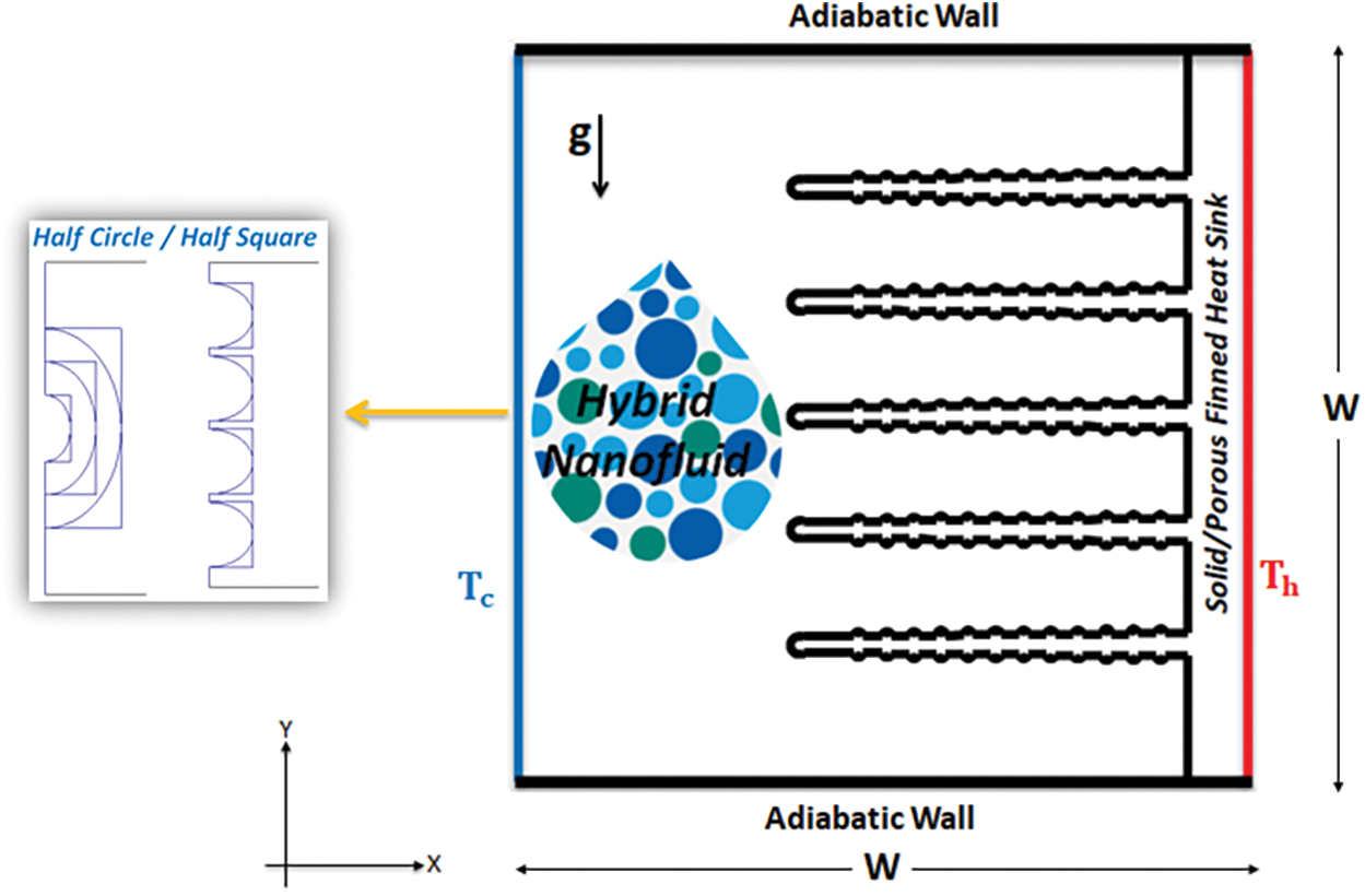
Figure 2: Physical geometry of the proposed enclosure model
The present study encompasses three elements: the hybrid nanofluid [42,43], the porous fin [42,44], and the solid heat sink [45]. Hence, the dimensionless governing equations are two-dimensional Cartesian coordinates and consist of three states.
Hybrid Nanofluid
Continuity Equation:
Momentum Equation:
Energy Equation:
Porous Fin
Continuity Equation:
Momentum Equation:
Energy Equation:
Solid Heat Sink
Energy Equation:
The above dimensionless equations are obtained using dimensionless parameters and numbers:
To determine the impact of the various factors, this study calculates the Average Nusselt Number along the surface of the heat sink [17,46,47].
It is important to note that the (khnfs) refers to (khnf) for the hybrid nanofluid phase and the term (ks) represent the solid phase.
In the stream function equation, the velocity components of the two-dimensional flow determine the dimensional formula.
According to the equation, the stream function is negative when fluid flow anticlockwise and positive when fluid flows clockwise.
2.3 Hybrid Nanofluid Thermophysical Properties
The following equations determine hybrid nanofluid thermophysical properties (density, thermal expansion, heat capacitance, thermal diffusivity, and dynamic viscosity) [48,49].
2.4 Initial Boundary Conditions
As can be seen in Fig. 2, the boundary conditions of the computational domain are depicted:
1. A wall on the right side of the enclosure:
2. A wall on the left side of the enclosure:
3. Walls are on the top and bottom sides of the enclosure:
4. Boundary between the hybrid nanofluid and heat sink with porous fins:
5. On all boundaries:
2.5 Numerical Method and Grid Independence
The COMSOL Multiphysics program is utilized to solve the governing dimensionless equations. Finite element methods are employed to calculate the stream function, isotherms, and average Nusselt numbers within the enclosure. The current study employs iteration where the convergence threshold error for each variable is equal to or less than (10−6). The computational domain is represented by a triangular mesh element in a two-dimensional Cartesian coordinate system, as depicted in Fig. 3. To select the grid-independent solution, compare the maximum value of the stream function inside the cavity and the average Nusselt number on the surface of the heat sink with porous fins for all predefined mesh sizes, as indicated in Table 2. The test utilizes the following parameters (Ra = 103, Da = 10−2, ϕ = 0.02, N = 0, S = 0). The outcome demonstrates a precise resolution for Extra Fine (539,15) in comparison to Extremely Fine (59,207), so in this particular investigation, Extra Fine is chosen.
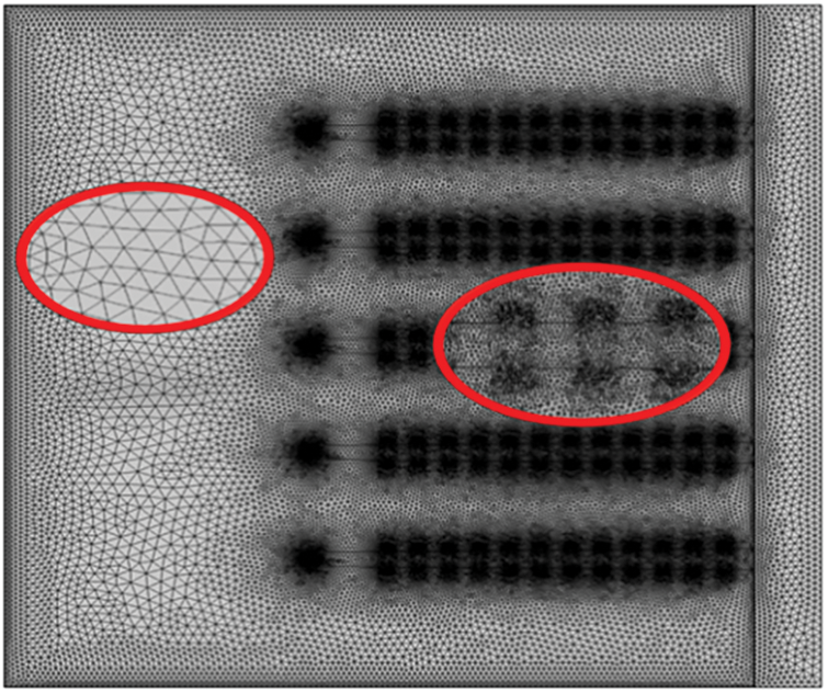
Figure 3: Triangular mesh utilized for the enclosure and heat sink

The objective of code validation is to ascertain the accuracy and reliability of simulation results by comparing them to reliable research. This will increase our confidence in the code’s capacity to accurately represent physical occurrences and help solve technical challenges. The temperature distribution lines and flow function lines were compared with Siavashi et al. [50] conducted a study on natural convection and entropy formation within a square cavity filled with nanofluid. The comparison is illustrated in Fig. 4, utilizing the parameters (Ra = 106, Da = 10−4,
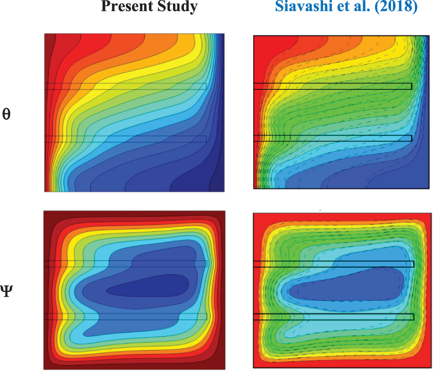
Figure 4: Comparison of isotherms (θ) and streamlines (Ψ) with Siavashi et al. [50] at (Ra = 106, Da = 10−4,
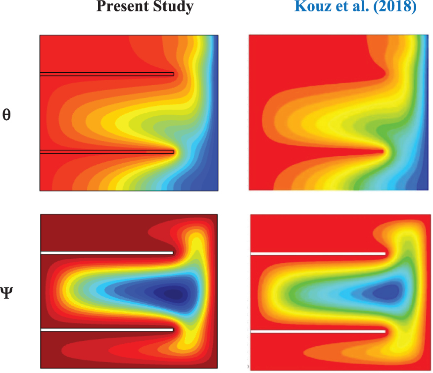
Figure 5: Comparison of isotherms (θ) and streamlines (Ψ) with AI-Kouz et al. [51] at (Ra = 105, HF = 0.25_0.75, FL = 0.75 m, θ = 0°, and Kn = 0)

In this section, the results of numerical simulations for the current study are presented, which include heat sinks with solid and porous fins inside a cavity with a hot right wall and a cold left wall, and the upper and lower walls are thermally insulated filled with a hybrid nanofluid ((MWCNT and Fe3O4) and water as the base fluid). This has been explained in detail and dimensions in Section 2.1.
The research results were summarized in six sections. It begins by studying the heat sink with solid fins and then modifies it to porous fins. Then choose the best results from Section 3.1 to make cuts in the cold wall (half circle/half square) in different numbers and sizes. The best results from Sections 3.2 and 3.3 are also selected to change the location of the cuts in the cold wall in Section 3.4. The effects of different solid volume fractions of hybrid nanofluid are also examined for heat sink with both solid and porous finned in Section 3.5.
The results showed the Stream function (Ψ) and Isotherms lines (θ) represented in the left column and right column respectively of the Figs. 5–15. As well as the Average Nusselt Number shown in Section 3.6 of the results presented in Figs. 16–20.
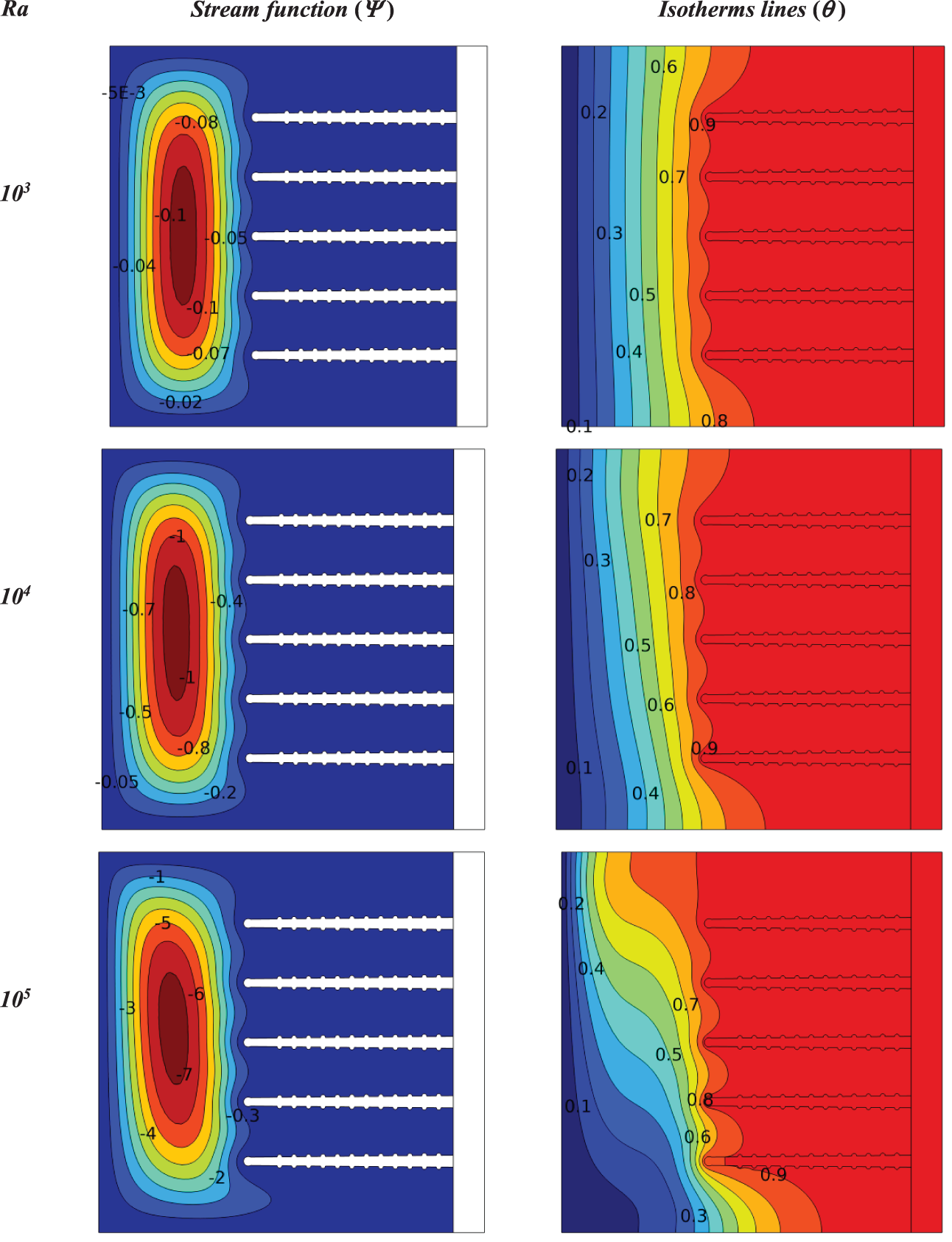
Figure 6: Influence Rayleigh number on contours of isotherms and stream functions for a heat sink with solid fins at (
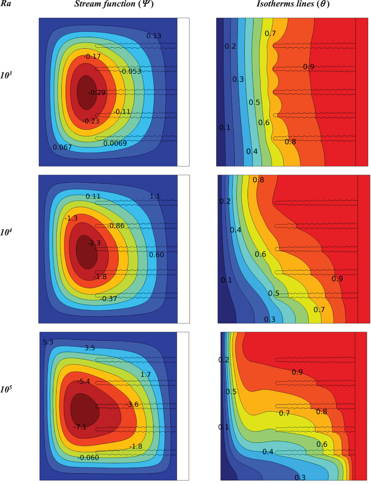
Figure 7: Influence Rayleigh number on contours of isotherms and stream functions for a heat sink with porous fins at (Da = 10−3, ϕ = 0.04, N = 0, S = 0)
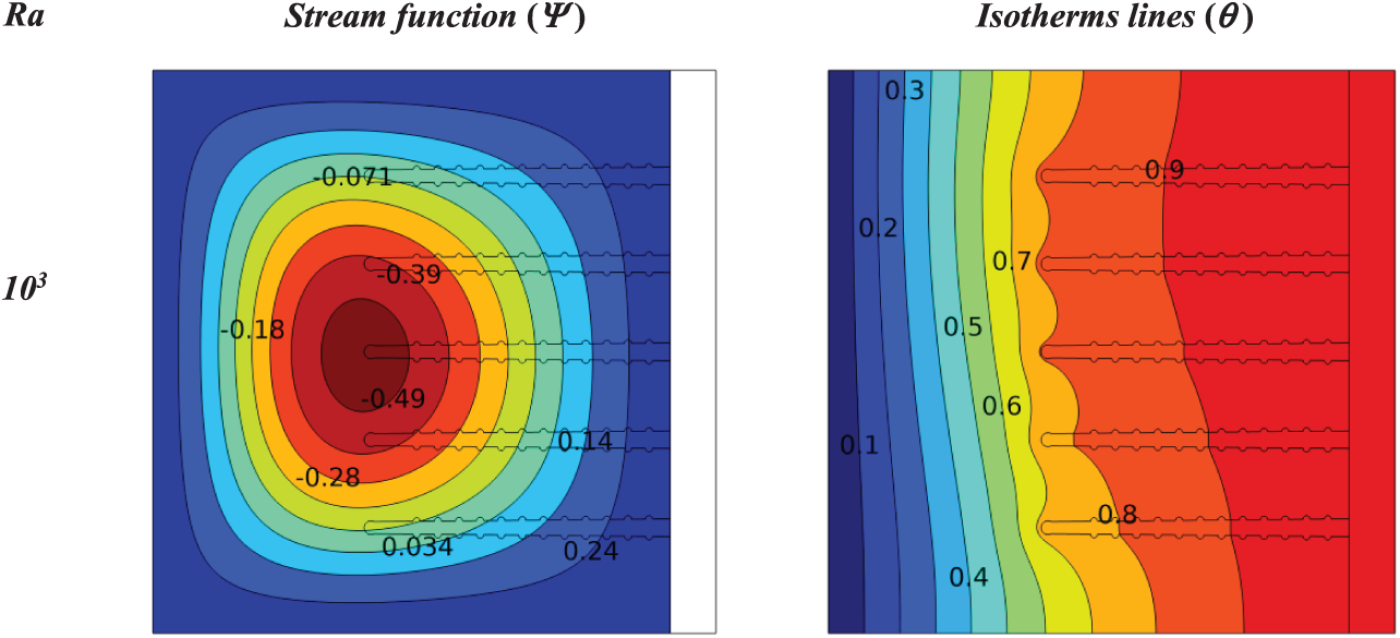
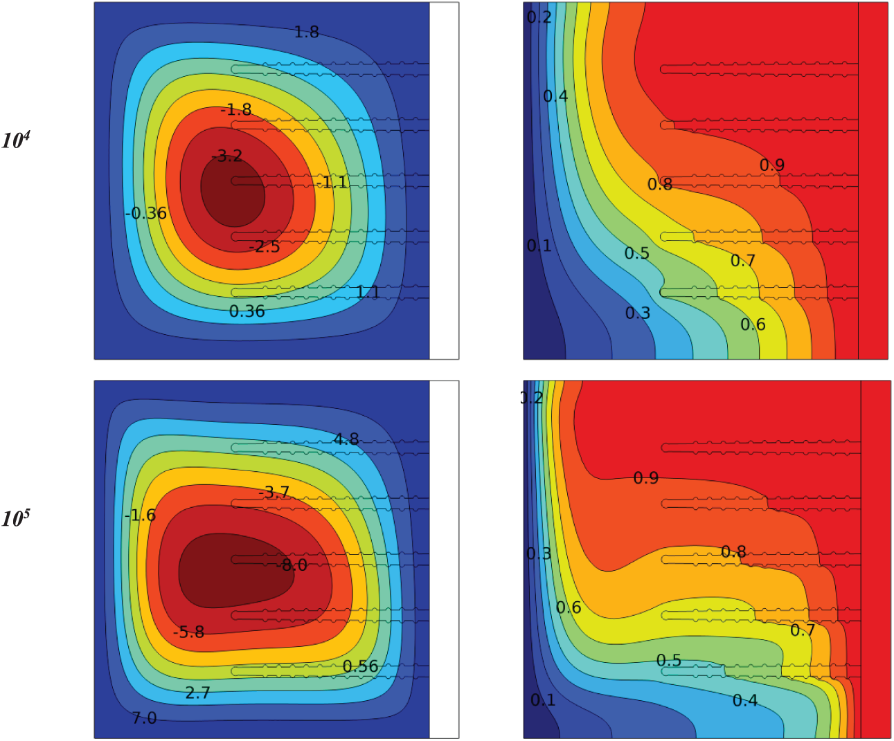
Figure 8: Influence Rayleigh number on contours of isotherms and stream functions for a heat sink with porous fins at (Da = 10−2, ϕ = 0.04, N = 0, S = 0)
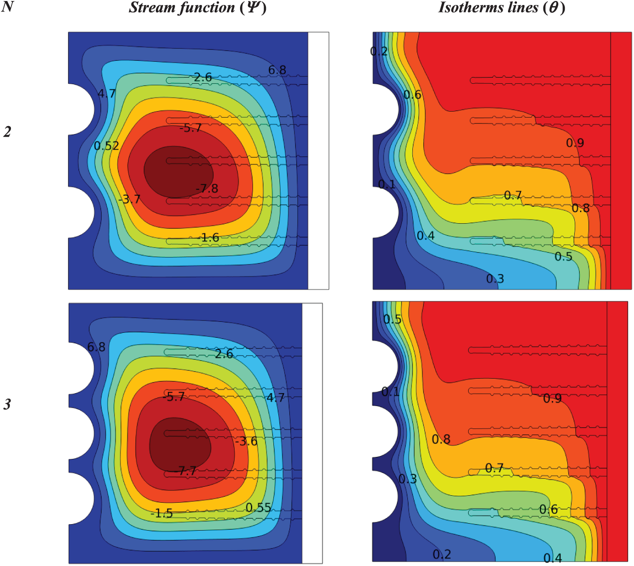
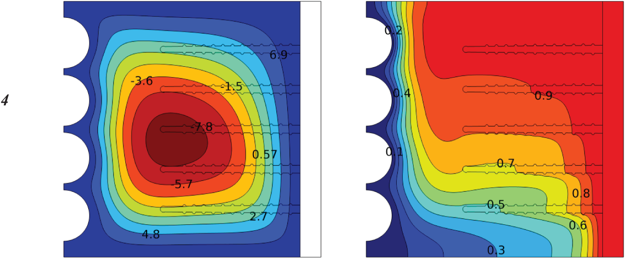
Figure 9: Influence number of (half circle) in a cold wall on the contours of isotherms and stream functions for a heat sink with porous fins at (Ra = 105, Da = 10−2, ϕ = 0.04, S = 0.1)
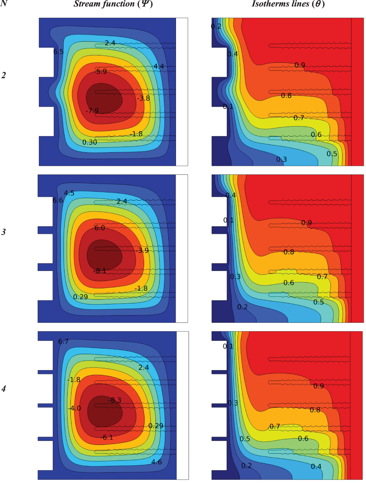
Figure 10: Influence number of (half square) in a cold wall on the contours of isotherms and stream functions for a heat sink with porous fins at (Ra = 105, Da = 10−2, ϕ = 0.04, S = 0.1)
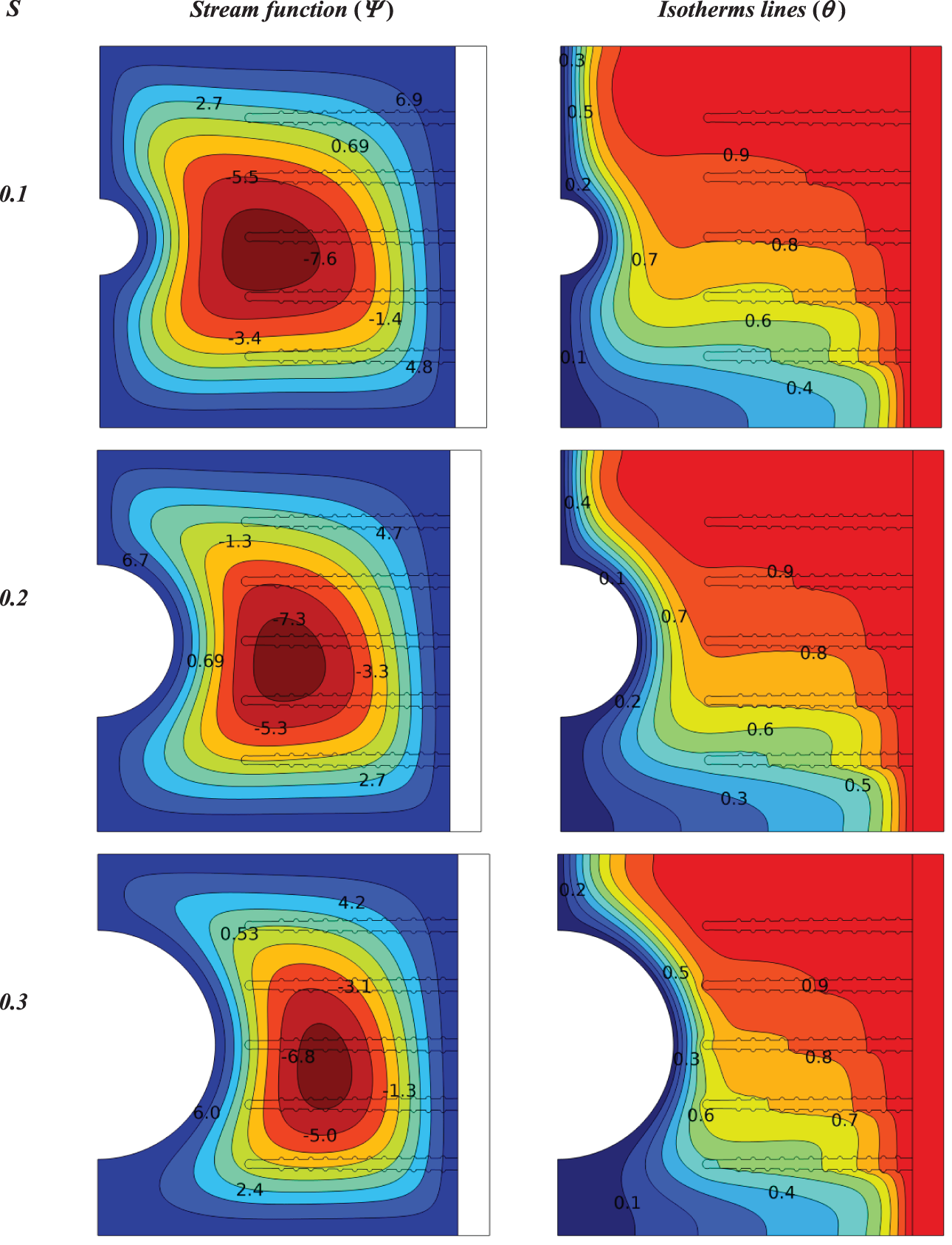
Figure 11: Influence size of (half circle) in a cold wall on the contours of isotherms and stream functions for a heat sink with porous fins at (Ra = 105, Da = 10−2, ϕ = 0.04, N = 1, C = 0.5)
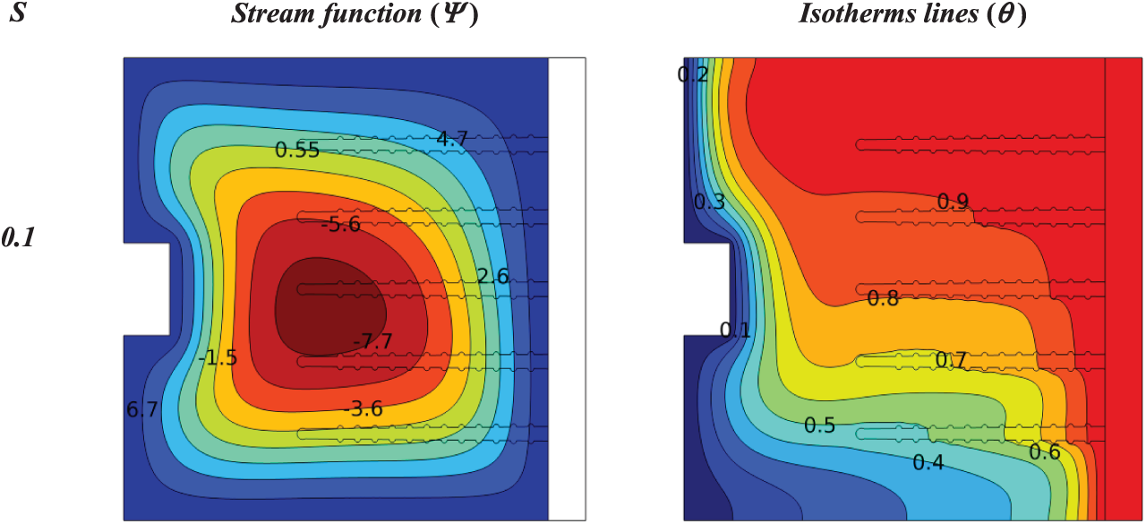
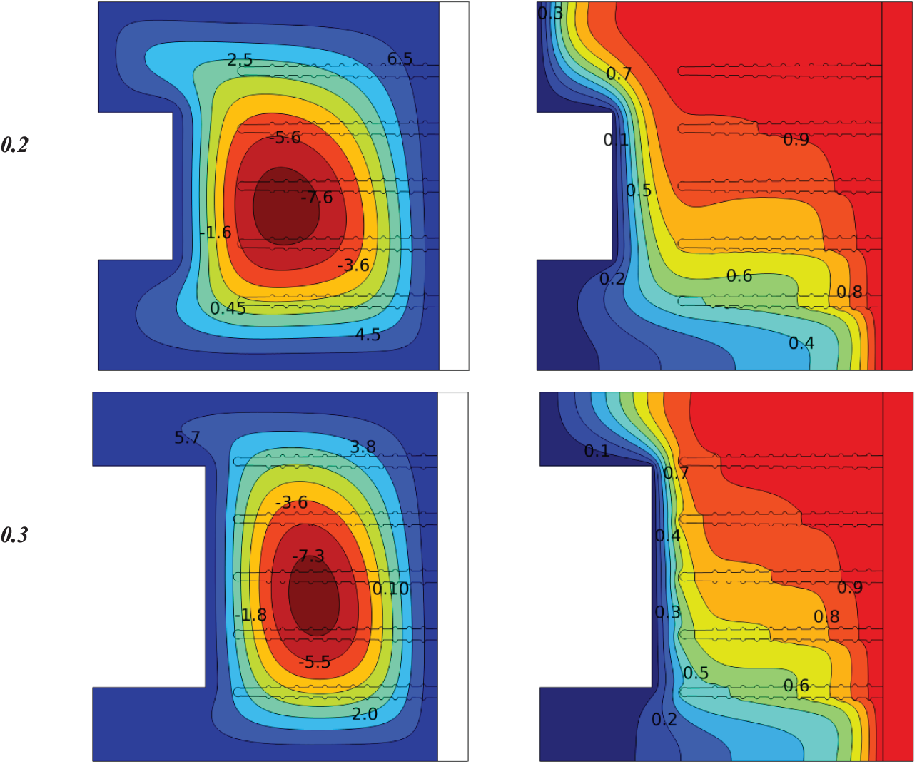
Figure 12: Influence size of (half square) in a cold wall on the contours of isotherms and stream functions for a heat sink with porous fins at (Ra = 105, Da = 10−2, ϕ = 0.04, N = 1, C = 0.5)
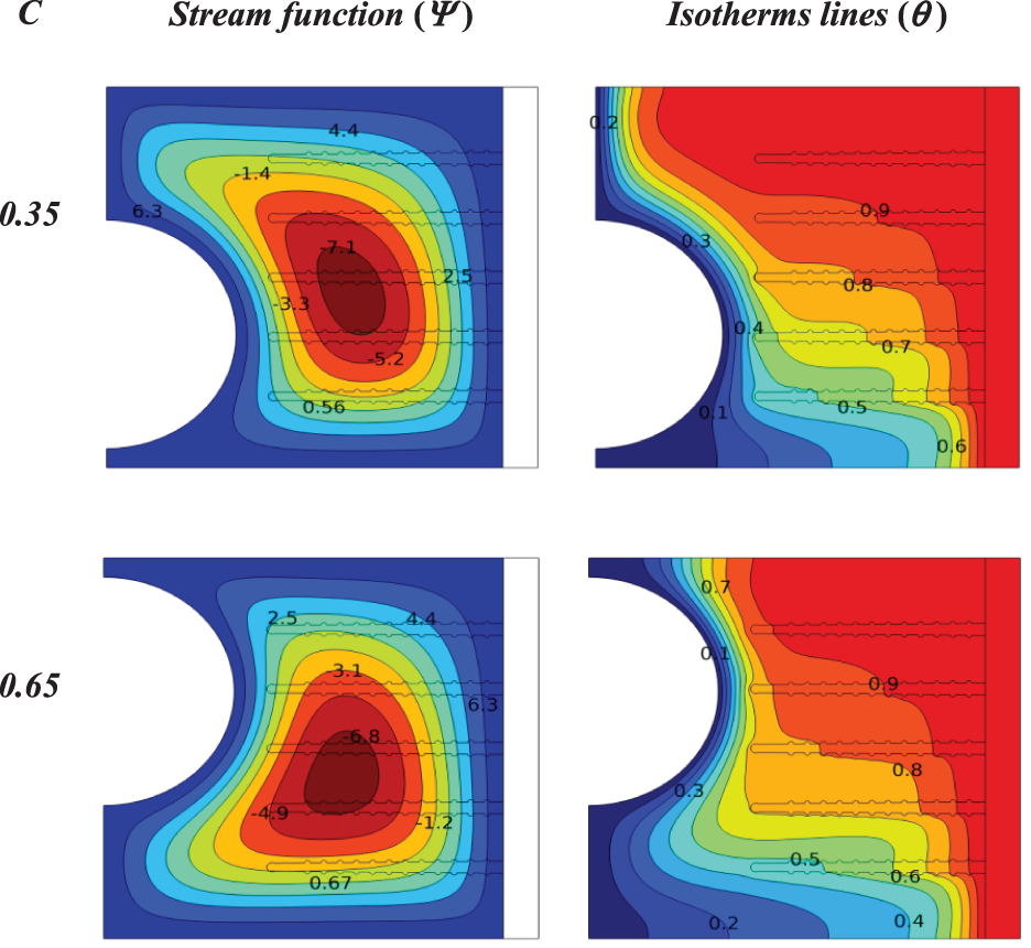
Figure 13: Influence location of (half circle) in a cold wall on the contours of isotherms and stream functions for a heat sink with porous fins at (Ra = 105, Da = 10−2, ϕ = 0.04, N = 1, S = 0.3)
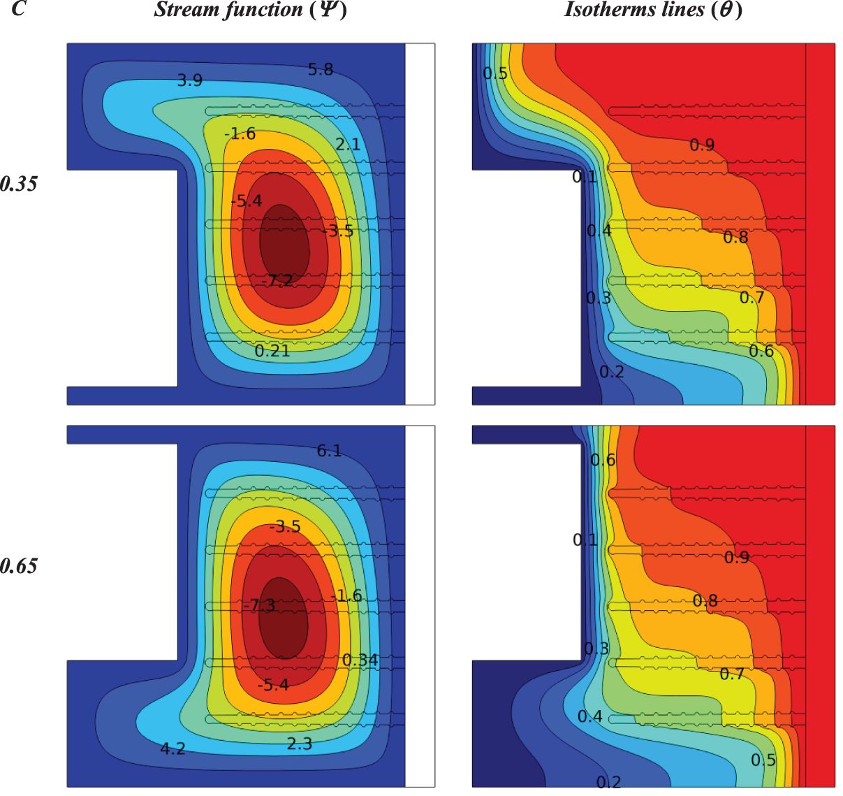
Figure 14: Influence location of (half square) in a cold wall on the contours of isotherms and stream functions for a heat sink with porous fins at (Ra = 105, Da = 10−2, ϕ = 0.04, N = 1, S = 0.3)
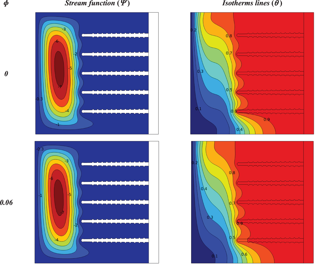
Figure 15: Influence solid volume fraction on the contours of isotherms and stream functions for a heat sink with solid fins at (Ra = 105, N = 0, S = 0)
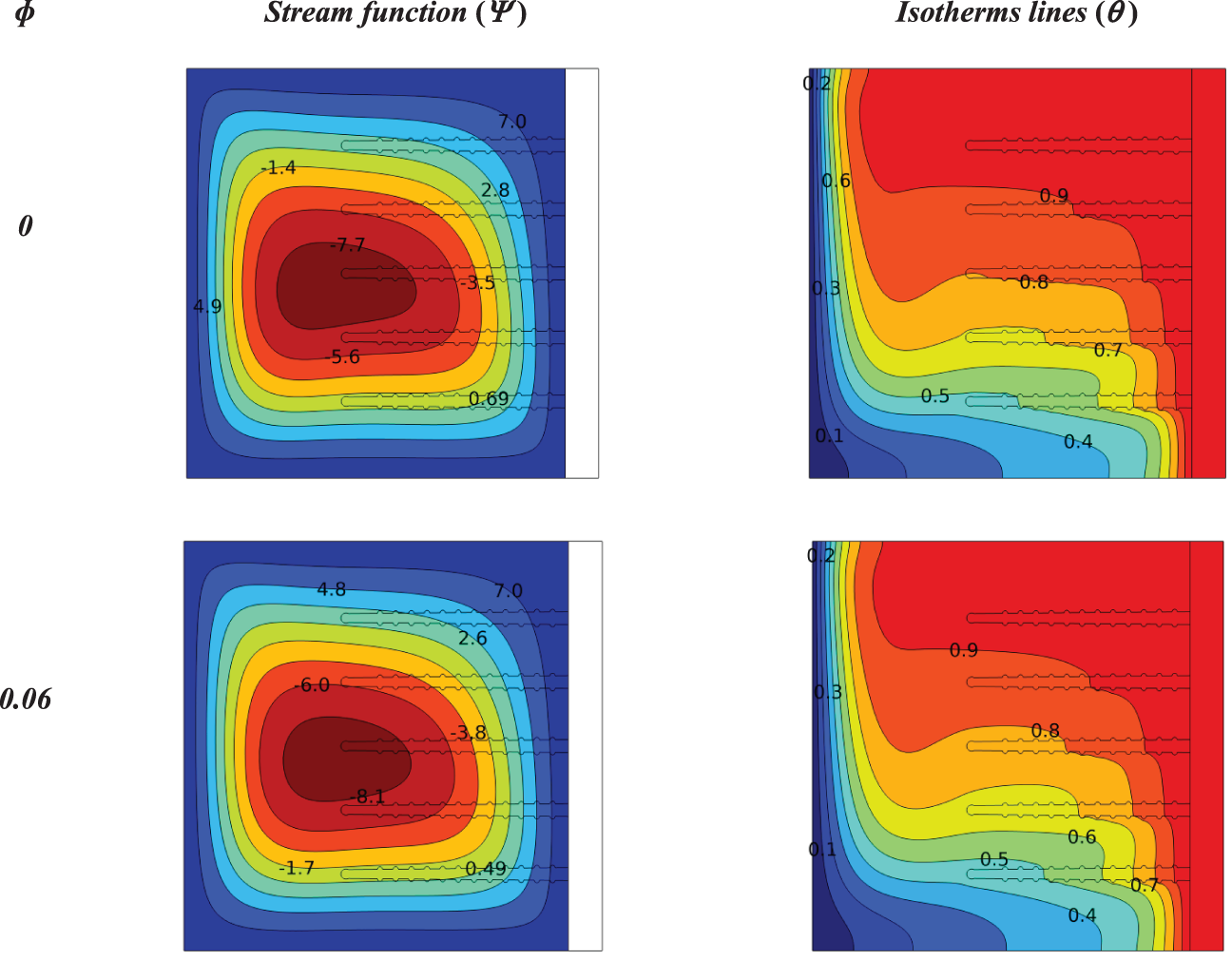
Figure 16: Influence solid volume fraction on the contours of isotherms and stream functions for a heat sink with porous fins at (Ra = 105, Da = 10−2, N = 0, S = 0)
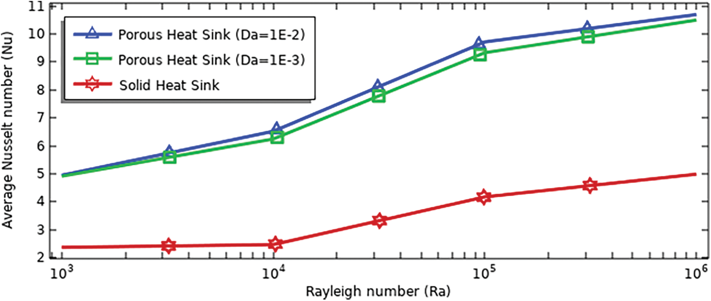
Figure 17: Average Nusselt number for various Rayleigh numbers and heat sink type at (ϕ = 0.04, N = 0, S = 0)
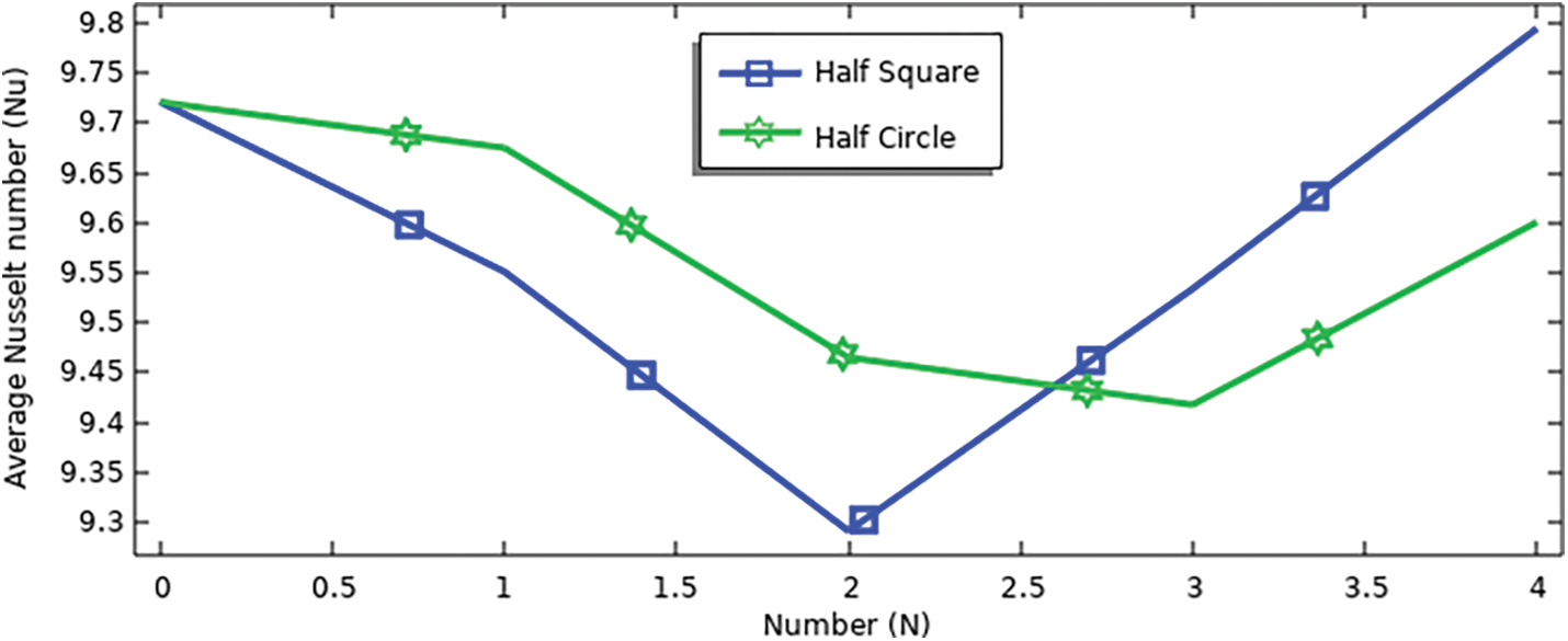
Figure 18: Average Nusselt number for various number of (half circle and half square) at (Ra = 105, Da = 10−2, ϕ = 0.04, S = 0.1)
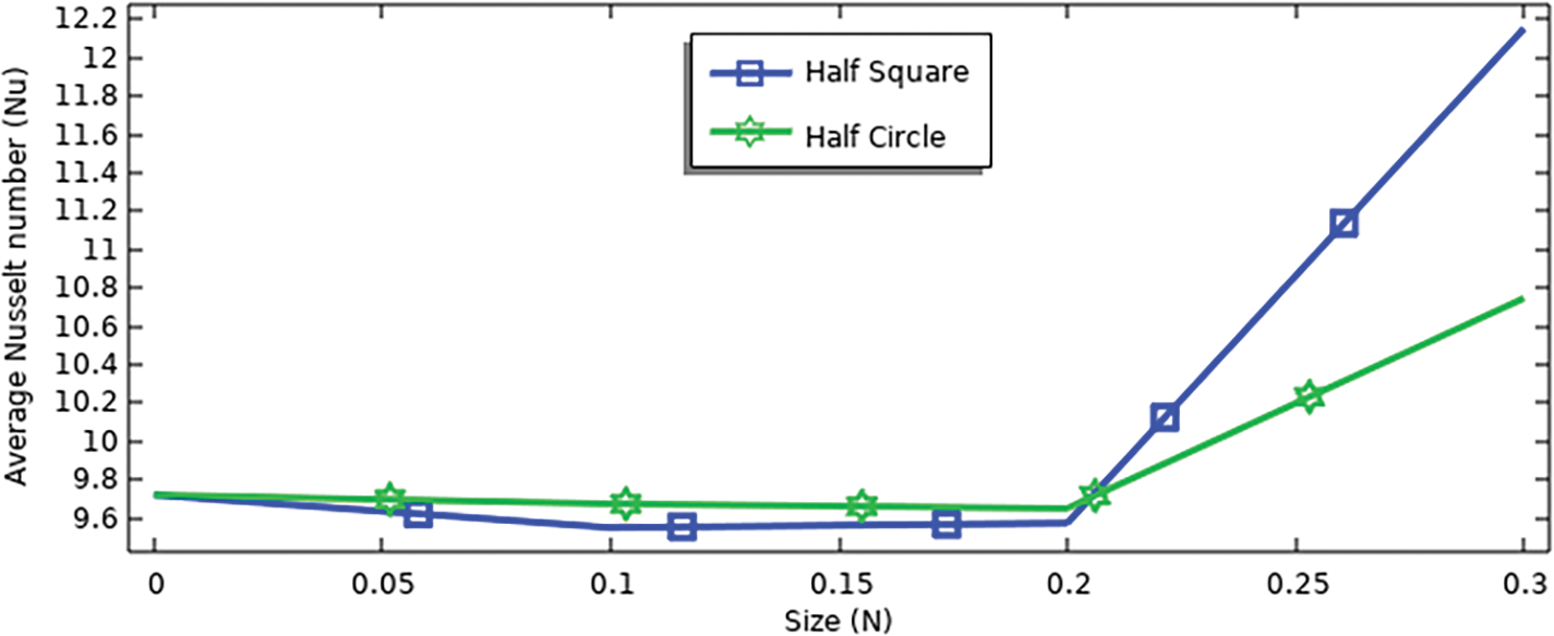
Figure 19: Average Nusselt number for various size of (half circle and half square) at (Ra = 105, Da = 10−2, ϕ = 0.04, N = 1)
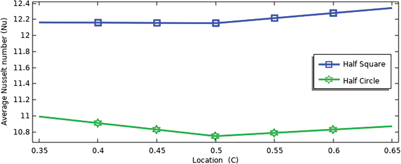
Figure 20: Average Nusselt number for various locations of (half circle and half square) at (Ra = 105, Da = 10−2, ϕ = 0.04, N = 1, S = 0.3)
The parameters used in this study are Rayleigh number (Ra = 103 to 106), Darcy number (Da = 10−2, and 10−3), solid volume fraction (
3.1 Influence Rayleigh Number and Darcy Number for Heat Sink with Solid and Porous Fins
Generally buoyant force is responsible for generating the flow field inside the cavity during natural convection heat transfer between the heat sink attached hot right wall and the left cold wall. Consequently, the flow vortices originate from the heat sink and rise towards the thermally isolated upper horizontal wall to complete their downward motion due to their impact on the cold left wall, and subsequently complete their motion towards the isolated lower horizontal wall.
Fig. 6 shows the effect of the Rayleigh number (103 to 105) on the isotherm lines and stream function for a solid-finned heat sink at (
From the left column of the figure, noticed that the flow lines for all Rayleigh numbers are confined between the tip fins of the heat sink and the cold wall due to the small distance between the fins, which makes difficult movement of fluid. At Rayleigh number 103, noticed that the highest value of the stream function (Ψmax = 0.2), increases with the increase of Rayleigh number, as it is at 104 (Ψmax = 1.21), while the highest value (Ψmax = 7.3) when Rayleigh number reaches 105 is concluded that increasing the Rayleigh number from 103 to 105 increases the stream function by 97%.
As for the right column of Fig. 6, it is noted at Rayleigh number 103 that the fins area has uniform temperature, while the lines are vertical between the tip of the fins and cold wall due to the low Rayleigh number value. Therefore, it is observed that the isotherms lines tilt slightly when the Rayleigh number 104, while at the Rayleigh number 105, the effect is more evident as the isotherms lines extend from the tip of fins, especially at the first fin from the bottom due to increasing heat transfer.
Now the solid fins of the heat sink are replaced by the porous fins. Fig. 7 shows the effect of the Rayleigh number on the isotherms and stream function for a heat sink with porous fins at (Da = 10−3, ϕ = 0.04, N = 0, S = 0).
From the left column, it is observed the streamline covers the cavity, unlike solid fins, because porous fins allow the fluid to penetrate through them. When the Rayleigh number 103, the highest value of the stream function is (Ψmax = 0.32), while when the Rayleigh number 104, it is (Ψmax = 2.56), and at Rayleigh number 105, the vortices inside the cavity expand due to the increase in heat transfer, to be (Ψmax = 8).
The percentage increase in the stream functions when the Rayleigh number is increased from 103 to 105 is 96%.
In the right column, it is observed that the temperature distribution includes the heat sink fins, where at a Rayleigh number 103 the gradient reaches approximately the middle of the fins and continues to expand when the Rayleigh number is increased to include four fins. Also, the isothermal lines change from vertical to horizontal due to the increase in heat transfer.
When the Darcy number is increased, as in Fig. 8, which shows the effect of the Rayleigh number on the isotherm lines and stream functions for a heat sink with porous fins at (Da = 10−2, ϕ = 0.04, N = 0, S = 0).
It is the same physical interpretation as the previous figure, but the fluid more freely flows inside the fins, as at the Rayleigh number 103, it is (Ψmax = 0.54) and at the Rayleigh number 104, it is (Ψmax = 3.6), while it is (Ψmax = 9.1) at the Rayleigh number 105. The rate of increase in the stream function from Rayleigh number 103 to 105 is 94%.
As for the isotherm lines, the same explanation as before, but the cooling of the fins is greater due to the high permeability of the porous fins.
When comparing the above three figures at Rayleigh number 105, it is noted that the stream functions increased by 9% when replacing the solid fins with the porous fins at Darcy number 10−3 and by 20% at Darcy number 10−2.
3.2 Influence of the Different Numbers of Configurations (Half Circle & Half Square)
After obtaining the best results from the previous section, an attempt is now made to improve heat transfer by changing the shape of the cold wall using shapes (half circle/half square) with different numbers.
Fig. 9 explains the effect of the (half circle) with different numbers (2, 3, 4) in the cold wall on the isotherm lines and stream functions for a heat sink with porous fins at (Ra = 105, Da = 10−2, ϕ = 0.04, S = 0.1).
It is noted that the highest value of the stream function is almost equal for all numbers, as (Ψmax = 8.9) for the number 2, (Ψmax = 8.8) for the number 3, and (Ψmax = 8.9) for the number 4. It turns out that the percentage of the stream function did not increase, but rather decreased by 2%.
There is also no clear change in the isotherm lines, as the three fins at the bottom are cooler than the two upper fins.
Fig. 10 explains the effect of (half square) with different numbers (2, 3, 4) in the cold wall on the isotherm lines and stream functions for a heat sink with porous fins at (Ra = 105, Da = 10−2, ϕ = 0.04, S = 0.1).
In this case, the highest value of the stream function at number 2 is equal to (Ψmax = 9), and at number 3 it is equal to (Ψmax = 9.1), while at number 4 it is equal to (Ψmax = 9.3). In numbers 2 and 3, it is equal to the case of the vertical cold wall, while it increases by 2% in number 4. Also, the isotherm lines expand slightly in the fourth fin to be more cooling.
3.3 Influence of the Different Sizes of Configurations (Half Circle & Half Square)
This section discusses improving heat transfer in the cavity by using different shapes (half circle/half square) on the cold wall with different sizes.
Fig. 11 shows the effect of (half circle) with different sizes (0.1, 0.2, 0.3) in the middle of the cold wall on the isotherms and stream functions for a heat sink with porous fins at (Ra = 105, Da = 10−2, ϕ = 0.04, N = 1, C = 0.5). In the right column, the streamlines are concave due to the shape of the cold wall, and the highest value of the stream function (Ψmax = 8.6) is a size of 0.1 and (Ψmax = 8.3) is at 0.2, while (Ψmax = 7.7) is at 0.3. The lowest value of the stream function is observed at size 0.3 because the fluid moves only around the porous fins and has no region to move in the cavity. Yes, the value of the stream is low, but noticed here greater cooling of the fins, which means there is greater heat transfer.
Likewise, for the isotherm lines, it is evident that there is greater cooling of the fins at size 0.3, where the (θ = 0.8) line has expanded to include half of the middle fin.
Fig. 12 explains the effect of (half square) with different sizes (0.1, 0.2, 0.3) in the middle of the cold wall on the isotherm lines and stream functions for a heat sink with porous fins at (Ra = 105, Da = 10−2, ϕ = 0.04, N = 1, C = 0.5).
In this case, the highest value of the stream function is (Ψmax = 8.7) for size 0.1, (Ψmax = 8.6) for size 0.2, and (Ψmax = 8.3) for size 0.3. Also, the value of the stream function is lowest at a size of 0.3, but the streamlines extend to the top and bottom, and in this case, it includes almost all the fins.
In the isotherms lines, it was distributed perfectly around the fins and was approximately 25% better than the (half circle) of size 0.3.
3.4 Influence of the Different Location of Configurations (Half Circle & Half Square)
After obtaining the required improvement when converting the heat sink fins from solid to porous, and then changing the shape of the cold wall, the best results were obtained from the previous sections of the study when the size (half circle/half square) was 0.3 in the middle of the cold wall. The shapes will now be moved up and down to try to get the best results.
Fig. 13 shows the effect of the location (half circle) in the cold wall on the isotherms and stream functions for a heat sink with porous fins at (Ra = 105, Da = 10−2, ϕ = 0.04, N = 1, S = 0.3).
The highest value of the stream function at the location is 0.35 (Ψmax = 8.1). It is noted that it is higher than the previous location of 0.5 due to giving additional space for the fluid to move inside the cavity, but the streamlines are slightly inclined, so they cover the fins less.
At location 0.65, the stream function will be equal to location 0.5 (Ψmax = 7.7) because the flow lines will collide from the top with (half circle) and travel with the bottom cold wall, which demonstrates a greater improvement in cooling the fins.
The isotherm lines are better distributed at location 0.65, as they give greater cooling to the upper fin due to its proximity to (half circle).
The same interpretation above is for Fig. 14, which shows the effect of the location (half square) in the cold wall on the isotherm lines and stream functions for a heat sink with porous fins at (Ra = 105, Da = 10−2, ϕ = 0.04, N = 1, S = 0.3). Where the flow function is (Ψmax = 8.1) for location 0.35 and (Ψmax = 8.3) for location 0.65. But in this case, the heat transfer is greater because the shape (half square) limits the fluid to flow around the porous fins more than it does (half circle), and this is evident in the good distribution of isotherm lines inside the cavity.
3.5 Influence of the Solid Volume Fraction
In this section, the effect of using (hybrid nanofluid) with nanoparticles (MWCNT and Fe3O4) is clarified and compared with the basic fluid (water).
Fig. 15 shows the effect of solid volume fraction on isotherm lines and stream functions for a solid-finned heat sink at (Ra = 105, N = 0, S = 0).
The highest value of the stream function was (Ψmax = 7.4) for water, while (Ψmax = 7.9) increased when using the hybrid nanofluid
Fig. 16 shows the effect of solid volume fraction on isotherm lines and stream functions for a heat sink with porous fins at (Ra = 105, Da = 10−2, N = 0, S = 0).
The highest value for the stream function was (Ψmax = 8.7) for water and (Ψmax = 9.2) for the hybrid nanofluid, meaning the ratio increased by the same value for the heat sink with solid fins. Also, the isotherm lines got closer to the fins and expanded, especially at the bottom four fins, which means an increase in heat transfer.
Finally, in this section, the average Nusselt number (Nu) is calculated along the length of the heat sink and the extent to which it is affected by the parameters studied in the previous sections.
Fig. 17 shows the Nu for different Rayleigh numbers (103 to 106) of a heat sink with solid fins and a porous fin with a Darcy number (10−3 and 10−2) at (ϕ = 0.04, N = 0, S = 0). A clear increase in the Nu is observed by increasing the Rayleigh number by 44% for solid fins and by 50% for porous fins. The rate of increase in the Nu when converting the fins from solid to porous is 54% at Rayleigh number 106.
Fig. 18 shows the Nu for (half circle and half square) using different numbers (0 to 4) at (Ra = 105, Da = 10−2, ϕ = 0.04, S = 0.1).
At (half circle) noticed a decrease in the Nu 1.5% by comparing the numbers 0 and 4, and at (half square) the number begins to decrease until the number 2 and then increases to reach the highest value at the number 4 by 1% compared to the number zero. When compared to number 4, found that Nu at (half square) is increased by 2% than (half circle).
Fig. 19 shows the Nu for (half circle and half square) with different sizes (0 to 0.3) at (Ra = 105, Da = 10−2, ϕ = 0.04, N = 1).
It is noted that the Nu decreases when the size 0.2 increases, but after that, it begins to increase until it reaches the highest value at the size 0.3, where the percentage of increase is 10% at (half circle) and 21.5% at (half square). If the comparison is made at size 0.3, it will be noted that the Nu at (half a square) is higher than (half a circle) by 11.6%.
Fig. 20 shows the Nu for (half circle and half square) with different locations (0.35 to 0.65) at (Ra = 105, Da = 10−2, ϕ = 0.04, N = 1, S = 0.3).
At (half circle), it is noted that the highest value of Nu is at the location 0.35, where the value of Nu increases by 2% at location 0.5. While at (half square), the highest value is reached at the location of 0.65, with an increase of 2% over the location of 0.5.
When comparing the best values of Nu at (half circle) and (half square), it is noted that the highest value of Nu is at (half square), with an increase of 11%.
Fig. 21 shows the Nu for different values of solid volume fractions (0 to 0.06) and Rayleigh numbers (103 to 106) for a heat sink with solid fins at (N = 0, S = 0).
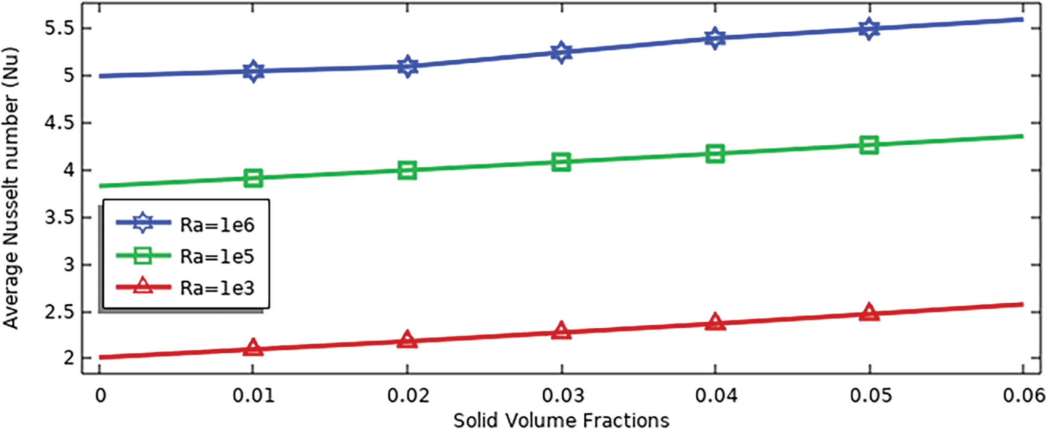
Figure 21: Averaged Nusselt number for various values of solid volume fractions and Rayleigh numbers for a heat sink with solid fins at (N = 0, S = 0)
In general, the value of Nu with increased solid volume fractions for all Rayleigh numbers increases by approximately 23%. The highest value of Nu is obtained at the Rayleigh number 106 and ϕ = 0.06, which reaches 5.5.
The present study contributed to enhancing heat transfer within a cavity filled with a hybrid nanofluid and in the presence of a heat sink with solid fins. This was achieved by replacing the solid fins with porous fins. Additionally, further improvements were made by including cold walls with configurations of (half circle/half square) in different sizes, numbers, and locations. Various parameters such as Rayleigh number, Darcy number, and solid volume fraction were employed.
Based on the outcomes of numerical simulations, several significant conclusions can be presented:
• For a heat sink with solid fins when increasing the Ra from 103 to 105 increases the stream function by 97%. While at a heat sink with porous fins 96% for Da = 10−3 and 94% for Da = 10−2.
• The stream functions increase when converting the fins from solid to porous by 9% at Da = 10−3 and by 20% at Da = 10−2.
• For porous fins and (half circle) with different numbers (2, 3, 4) in the cold wall the percentage of the stream function decreased by 2%, and for (half square) the numbers 2 and 3, it is equal to the case of the vertical cold wall, while it increases by 2% in number 4.
• The lowest value of the stream function is observed at size 0.3 for (half circle/half square) while the isotherms lines for (half square), it was distributed perfectly around the fins and were approximately 25% better than the (half circle) of size 0.3.
• When changing the location of (half a circle/half a square) on the cold wall the shape of (half a square) gives better values for the stream function than (half a circle).
• When using the hybrid nanofluid by 0.06, the value of the stream function increases by about 5.6% for the heat sink, whether with solid or porous fins, compared to water. The cooling of the fins also increases due to the expansion of the isotherm lines towards the fins.
• Nu increases with increasing Ra by 44% for solid fins and by 50% for porous fins. The rate of increase in Nu when converting the fins from solid to porous is 54% at Ra = 106.
• The highest Nu values were obtained at (half a square) compared to (half a circle), with an increase of 2% for different numbers, 11.6% at different sizes, and 11% at different locations.
• At a solid-finned heat sink the value of Nu increases with solid volume fractions for all Ra by approximately 23%.
• The present study presented significant improvements in Nusselt number, streamlines, isotherms, and solid volume fractions when compared with researchers that studied the heat sink inside the cavity, as Rashad et al. [53] and Chen et al. [54].
The improvements presented in this study can be utilized to increase heat dissipation in electronic applications by using a porous fin heat sink. In future studies, the current results can be utilized by conducting an experimental study of porous fin heat sinks. The fin shapes can be changed and cavities of different shapes can be used, such as triangular, circular, etc.
Acknowledgement: The authors would like to acknowledge the constructive remarks by worthy reviewers that led to this revised article.
Funding Statement: The authors received no specific funding for this study.
Author Contributions: The authors confirm contribution to the paper as follows: study conception and design: Ahmed Dhafer Abdulsahib, Dhirgham Alkhafaji, and Ibrahim M. Albayati; data collection, analysis, and interpretation of results: Ahmed Dhafer Abdulsahib; draft manuscript preparation: Ahmed Dhafer Abdulsahib, Dhirgham Alkhafaji, and Ibrahim M. Albayati. All authors reviewed the results and approved the final version of the manuscript.
Availability of Data and Materials: There is no data that is unavailable in this study.
Ethics Approval: Not applicable.
Conflicts of Interest: The authors declare no conflicts of interest to report regarding the present study.
References
1. Kaviany M. Principles of heat transfer in porous media. New York, NY, USA: Springer Science & Business Media; 2012. [Google Scholar]
2. Bejan A. Convection heat transfer. Hoboken, NJ, USA: John wiley & sons; 2013. [Google Scholar]
3. Al-Chlaihawi KK, Alaydamee HH, Faisal AE, Al-Farhany K, Alomari MA. Newtonian and non-Newtonian nanofluids with entropy generation in conjugate natural convection of hybrid nanofluid-porous enclosures: a review. Heat Transf. 2021;51(2):1725–45. doi:10.1002/htj.22372. [Google Scholar] [CrossRef]
4. Abdulkadhim A, Abed IM, Mahjoub Said N. Review of natural convection within various shapes of enclosures. Arab J Sci Eng. 2021;46(12):11543–86. doi:10.1007/s13369-021-05952-6. [Google Scholar] [CrossRef]
5. Abdulsahib AD, Alkhafaji D, Albayati IM. Thermal design and heat transfer analysis of heat sinks and enclosures: a review. Int J Heat Technol. 2024;42(4):1149–63. doi:10.18280/ijht.420405. [Google Scholar] [CrossRef]
6. Almensoury MF, Hashim AS, Hamzah HK, Ali FH. Numerical investigation of natural convection of a non-Newtonian nanofluid in an F-shaped porous cavity. Heat Transf. 2021;50(3):2403–26. doi:10.1002/htj.21984. [Google Scholar] [CrossRef]
7. Al-Farhany K, Al-Dawody MF, Hamzah DA, Hamza NH. Numerical study of nanofluid natural convection in a partially heated tall enclosure. IOP Conf Ser: Mater Sci Eng. 2020;928:022137. doi:10.1088/1757-899X/928/2/022137. [Google Scholar] [CrossRef]
8. Khademi A, Abtahi Mehrjardi SA, Said Z, Chamkha AJ. Heat transfer improvement in a thermal energy storage system using auxiliary fluid instead of nano-PCM in an inclined enclosure: a comparative study. J Appl Computat Mech. 2023;9(2):475–86. doi:10.22055/JACM.2022.41867.3829. [Google Scholar] [CrossRef]
9. Hai T, Alsharif S, Ali MA, Singh PK, Alizadeh A. Analyzing geometric parameters in inclined enclosures filled with magnetic nanofluid using artificial neural networks. Eng Anal Bound Elem. 2023;146(7):555–68. doi:10.1016/j.enganabound.2022.11.004. [Google Scholar] [CrossRef]
10. Yaghoubi Emami R, Siavashi M, Shahriari Moghaddam G. The effect of inclination angle and hot wall configuration on Cu-water nanofluid natural convection inside a porous square cavity. Adv Powder Technol. 2018;29(3):519–36. doi:10.1016/j.apt.2017.10.027. [Google Scholar] [CrossRef]
11. Abdulsahib AD, Hashim AS, Al-Farhany K, Abdulkadhim A, Mebarek-Oudina F. Natural convection investigation under influence of internal bodies within a nanofluid-filled square cavity. Eur Phys J Spec Top. 2022;231(13):2605–21. doi:10.1140/epjs/s11734-022-00584-9. [Google Scholar] [CrossRef]
12. Ibrahim MNJ, Hammoodi KA, Abdulsahib AD, Flayyih MA. Study of natural convection inside inclined nanofluid cavity with hot inner bodies (circular and ellipse cylinders). Int J Heat Technol. 2022;40(3):699–705. doi:10.18280/ijht.400306. [Google Scholar] [CrossRef]
13. Saha BK, Jihan JI, Ahammad MZ, Saha G, Saha SC. Enhanced thermal performance and entropy generation analysis in a novel cavity design with circular cylinder. Heat Transf. 2024;53(3):1446–73. doi:10.1002/htj.22999. [Google Scholar] [CrossRef]
14. Hussein AK. Computational analysis of natural convection in a parallelogrammic cavity with a hot concentric circular cylinder moving at different vertical locations. Int Commun Heat Mass Transf. 2013;46(4):126–33. doi:10.1016/j.icheatmasstransfer.2013.05.008. [Google Scholar] [CrossRef]
15. Al-Farhany K, Abdulsahib AD. Study of mixed convection in two layers of saturated porous medium and nanofluid with rotating circular cylinder. Prog Nucl Energy. 2021;135(4):103723. doi:10.1016/j.pnucene.2021.103723. [Google Scholar] [CrossRef]
16. Chordiya J, Sharma RV. Numerical analysis of the longitudinal size of the partition on natural convection heat transfer and fluid flow within a differentially heated porous enclosure. Heat Transf. 2023;52(1):890–910. doi:10.1002/htj.22721. [Google Scholar] [CrossRef]
17. Al-Srayyih BM, Gao S, Hussain SH. Effects of linearly heated left wall on natural convection within a superposed cavity filled with composite nanofluid-porous layers. Adv Powder Technol. 2019;30(1):55–72. doi:10.1016/j.apt.2018.10.007. [Google Scholar] [CrossRef]
18. Kadhim HT, Jabbar FA, Kadhim AA, Jaber AK, editors. Numerical study of nanofluid flow in a square cavity with porous medium using a sinusoidal interface. In: 2019 4th Scientific International Conference Najaf (SICN), 2019; Najaf, Iraq: IEEE. [Google Scholar]
19. Nguyen MT, Aly AM, Lee S-W. Effect of a wavy interface on the natural convection of a nanofluid in a cavity with a partially layered porous medium using the ISPH method. Numer Heat Trans Part A: Appl. 2017;72(1):68–88. doi:10.1080/10407782.2017.1353385. [Google Scholar] [CrossRef]
20. Singh A, Thorpe G. Natural convection in a confined fluid overlying a porous layer-a comparison study of different models. Ind J Pure Appl Mathemat. 1995;26:81–95. [Google Scholar]
21. Kasaeian A, Daneshazarian R, Mahian O, Kolsi L, Chamkha AJ, Wongwises S, et al. Nanofluid flow and heat transfer in porous media: a review of the latest developments. Int J Heat Mass Transf. 2017;107(6):778–91. doi:10.1016/j.ijheatmasstransfer.2016.11.074. [Google Scholar] [CrossRef]
22. Abdulsahib AD, Al-Farhany K. Review of the effects of stationary/rotating cylinder in a cavity on the convection heat transfer in porous media with/without nanofluid. Mathemat Modell Eng Prob. 2021;8(3):356–64. doi:10.18280/mmep.080304. [Google Scholar] [CrossRef]
23. Miroshnichenko IV, Sheremet MA, Oztop HF, Abu-Hamdeh N. Natural convection of alumina-water nanofluid in an open cavity having multiple porous layers. Int J Heat Mass Transf. 2018;125:648–57. doi:10.1016/j.ijheatmasstransfer.2018.04.108. [Google Scholar] [CrossRef]
24. Geridonmez BP, Oztop HF. Natural convection in a cavity filled with porous medium under the effect of a partial magnetic field. Int J Mech Sci. 2019;161(1–2):105077. doi:10.1016/j.ijmecsci.2019.105077. [Google Scholar] [CrossRef]
25. Alsabery A, Tayebi T, Abosinnee A, Raizah Z, Chamkha A, Hashim I. Impacts of amplitude and local thermal non-equilibrium design on natural convection within nanofluid superposed wavy porous layers. Nanomaterials. 2021;11(5):1277. doi:10.3390/nano11051277. [Google Scholar] [PubMed] [CrossRef]
26. Sudarsana Reddy P, Sreedevi P. Entropy generation and heat transfer analysis of magnetic hybrid nanofluid inside a square cavity with thermal radiation. Eur Phys J Plus. 2021;136(1):1–33. doi:10.1140/epjp/s13360-020-01025-z. [Google Scholar] [CrossRef]
27. Mathur P, Gupta AK, Panwar D, Sharma TK. Soft computing approaches for prediction of specific heat capacity of hybrid nanofluids. Expert Syst. 2024;41(1):e13471. doi:10.1111/exsy.13471. [Google Scholar] [CrossRef]
28. Chamkha AJ, Sazegar S, Jamesahar E, Ghalambaz M. Thermal non-equilibrium heat transfer modeling of hybrid nanofluids in a structure composed of the layers of solid and porous media and free nanofluids. Energies. 2019;12(3):541. doi:10.3390/en12030541. [Google Scholar] [CrossRef]
29. Ghalambaz M, Sheremet MA, Mehryan S, Kashkooli FM, Pop I. Local thermal non-equilibrium analysis of conjugate free convection within a porous enclosure occupied with Ag-MgO hybrid nanofluid. J Therm Anal Calorimet. 2019;135(2):1381–98. doi:10.1007/s10973-018-7472-8. [Google Scholar] [CrossRef]
30. Kadhim HT, Al Dulaimi ZM, Rona A. Local thermal non-equilibrium analysis of Cu-Al2O3 hybrid nanofluid natural convection in a partially layered porous enclosure with wavy walls. J Appl Computat Mech. 2023;9(3):712–27. doi:10.22055/jacm.2022.42046.3863. [Google Scholar] [CrossRef]
31. Kadhim HT, Jabbar FA, Rona A. Cu-Al2O3 hybrid nanofluid natural convection in an inclined enclosure with wavy walls partially layered by porous medium. Int J Mech Sci. 2020;186:105889. doi:10.1016/j.ijmecsci.2020.105889. [Google Scholar] [CrossRef]
32. Gangadhar K, Bhargavi DN, Kannan T, Venkata Subba Rao M, Chamkha AJ. Transverse MHD flow of Al2O3-Cu/H2O hybrid nanofluid with active radiation: a novel hybrid model. Math Methods Appl Sci. 2020;1–19. doi:10.1002/mma.6671. [Google Scholar] [CrossRef]
33. Dağdeviren A, Gedik E, Keçebaş A, Pazarlıoğlu HK, Arslan K, Alsabery AI. Effect of Al2O3–SiO2/water hybrid nanofluid filled in a square enclosure on the natural convective heat transfer characteristics: a numerical study. J Nanofluids. 2022;11(5):772–81. doi:10.1166/jon.2022.1881. [Google Scholar] [CrossRef]
34. Pazarlıoğlu HK, Gürsoy E, Gürdal M, Said Z, Arslan K, Gedik E. Numerical simulation of sudden expansion tubes with Ag-MgO nanofluid and innovative fin structure: a thermo-fluidic analysis. Int J Heat Fluid Flow. 2024;108:109448. doi:10.1016/j.ijheatfluidflow.2024.109448. [Google Scholar] [CrossRef]
35. Hatami M. Numerical study of nanofluids natural convection in a rectangular cavity including heated fins. J Molecul Liq. 2017;233(12):1–8. doi:10.1016/j.molliq.2017.02.112. [Google Scholar] [CrossRef]
36. Ma J, Xu F. Unsteady natural convection and heat transfer in a differentially heated cavity with a fin for high Rayleigh numbers. Appl Therm Eng. 2016;99:625–34. doi:10.1016/j.applthermaleng.2016.01.115. [Google Scholar] [CrossRef]
37. Gao D, Chen Z, Zhang D, Chen L. Lattice Boltzmann modeling of melting of phase change materials in porous media with conducting fins. Appl Therm Eng. 2017;118(1):315–27. doi:10.1016/j.applthermaleng.2017.03.002. [Google Scholar] [CrossRef]
38. Hatami M, Ganji D. Thermal performance of circular convective-radiative porous fins with different section shapes and materials. Energy Convers Manag. 2013;76(5):185–93. doi:10.1016/j.enconman.2013.07.040. [Google Scholar] [CrossRef]
39. Selimefendigil F, Öztop HF. Fuzzy-based estimation of mixed convection heat transfer in a square cavity in the presence of an adiabatic inclined fin. Int Commun Heat Mass Transf. 2012;39(10):1639–46. doi:10.1016/j.icheatmasstransfer.2012.10.006. [Google Scholar] [CrossRef]
40. Abdulsahib AD, Alkhafaji D, Albayati IM. Improving the natural convection of the heat sink inside an enclosure by fin perforation for electronic applications. Heat Transf. 2024;1–31. doi:10.1002/htj.23181. [Google Scholar] [CrossRef]
41. Al-Kouz W, Aissa A, Koulali A, Jamshed W, Moria H, Nisar KS, et al. MHD darcy-forchheimer nanofluid flow and entropy optimization in an odd-shaped enclosure filled with a (MWCNT-Fe3O4/water) using galerkin finite element analysis. Sci Rep. 2021;11(1):22635. doi:10.1038/s41598-021-02047-y. [Google Scholar] [PubMed] [CrossRef]
42. Mourad A, Aissa A, Mebarek-Oudina F, Jamshed W, Ahmed W, Ali HM, et al. Galerkin finite element analysis of thermal aspects of Fe3O4-MWCNT/water hybrid nanofluid filled in wavy enclosure with uniform magnetic field effect. Int Commun Heat Mass Transf. 2021;126:105461. doi:10.1016/j.icheatmasstransfer.2021.105461. [Google Scholar] [CrossRef]
43. Khanafer K, Vafai K, Lightstone M. Buoyancy-driven heat transfer enhancement in a two-dimensional enclosure utilizing nanofluids. Int J Heat Mass Trans. 2003;46(19):3639–53. doi:10.1016/S0017-9310(03)00156-X. [Google Scholar] [CrossRef]
44. Alsabery A, Chamkha A, Hashim I, Siddheshwar P. Effects of nonuniform heating and wall conduction on natural convection in a square porous cavity using LTNE model. J Heat Transf. 2017;139(12):122008. doi:10.1115/1.4037087. [Google Scholar] [CrossRef]
45. Gumir FJ, Al-Farhany K, Jamshed W, Tag El Din ESM, Abd-Elmonem A. Natural convection in a porous cavity filled (35% MWCNT-65% Fe3O4)/water hybrid nanofluid with a solid wavy wall via Galerkin finite-element process. Sci Rep. 2022;12(1):17794. doi:10.1038/s41598-022-22782-0. [Google Scholar] [PubMed] [CrossRef]
46. Basak T, Roy S, Paul T, Pop I. Natural convection in a square cavity filled with a porous medium: effects of various thermal boundary conditions. Int J Heat Mass Transf. 2006;49(7–8):1430–41. doi:10.1016/j.ijheatmasstransfer.2005.09.018. [Google Scholar] [CrossRef]
47. Hussain SH, Rahomey MS. Comparison of natural convection around a circular cylinder with different geometries of cylinders inside a square enclosure filled with Ag-nanofluid superposed porous-nanofluid layers. J Heat Transf. 2019;141(2):022501. doi:10.1115/1.4039642. [Google Scholar] [CrossRef]
48. Abu-Nada E, Chamkha AJ. Effect of nanofluid variable properties on natural convection in enclosures filled with a CuO-EG–water nanofluid. Int J Therm Sci. 2010;49(12):2339–52. [Google Scholar]
49. Brinkman HC. The viscosity of concentrated suspensions and solutions. J Chem Phys. 1952;20(4):571. doi:10.1063/1.1700493. [Google Scholar] [CrossRef]
50. Siavashi M, Yousofvand R, Rezanejad S. Nanofluid and porous fins effect on natural convection and entropy generation of flow inside a cavity. Adv Powder Technol. 2018;29(1):142–56. doi:10.1016/j.apt.2017.10.021. [Google Scholar] [CrossRef]
51. Al-Kouz W, Alshare A, Kiwan S, Al-Muhtady A, Alkhalidi A, Saadeh H. Two-dimensional analysis of low-pressure flows in an inclined square cavity with two fins attached to the hot wall. Int J Therm Sci. 2018;126:181–93. doi:10.1016/j.ijthermalsci.2018.01.005. [Google Scholar] [CrossRef]
52. Saeid NH. Natural convection in a square cavity with discrete heating at the bottom with different fin shapes. Heat Transf Eng. 2018;39(2):154–61. doi:10.1080/01457632.2017.1288053. [Google Scholar] [CrossRef]
53. Rashad A, Armaghani T, Chamkha AJ, Mansour M. Entropy generation and MHD natural convection of a nanofluid in an inclined square porous cavity: effects of a heat sink and source size and location. Chin J Phys. 2018;56(1):193–211. doi:10.1016/j.cjph.2017.11.026. [Google Scholar] [CrossRef]
54. Chen H-T, Zhang R-X, Yan W-M, Amani M, Ochodek T. Numerical and experimental study of inverse natural convection heat transfer for heat sink in a cavity with phase change material. Int J Heat Mass Transf. 2024;224:125333. doi:10.1016/j.ijheatmasstransfer.2024.125333. [Google Scholar] [CrossRef]
Cite This Article
 Copyright © 2024 The Author(s). Published by Tech Science Press.
This work is licensed under a Creative Commons Attribution 4.0 International License , which permits unrestricted use, distribution, and reproduction in any medium, provided the original work is properly cited.


 Submit a Paper
 Propose a Special lssue
 View Full Text
 Download PDF
 Downloads
 Citation Tools