 Open Access
ARTICLE
Features of Combustion of a Mixture of a Hydrogen Microjet with Various Gases
1 Khristianovich Institute of Theoretical and Applied Mechanics SB RAS, Novosibirsk, 630090, Russian
2 Kutateladze Institute of Thermophysics SB RAS, Novosibirsk, 630090, Russian
* Corresponding Author: Victor Kozlov. Email:
(This article belongs to the Special Issue: Heat and Mass Transfer in Energy Equipment)
Frontiers in Heat and Mass Transfer 2024, 22(6), 1695-1717. https://doi.org/10.32604/fhmt.2024.056866
Received 01 August 2024; Accepted 28 October 2024; Issue published 19 December 2024
Abstract
The objective of the present study is an experimental investigation of diffusion combustion of round microjets, i.e., mixtures of hydrogen with methane, helium, and nitrogen. It is found that the evolution of burning microjets is associated with generation of a “bottleneck flame region” close to the nozzle exit, as it was observed earlier during hydrogen combustion. Combustion of a mixture of hydrogen and methane with increasing flow velocity occurs with the transformation of the torch. At first, a torch stabilized on the nozzle is observed, then it is divided into a stabilized part in contact with the nozzle and into a raised part of the torch. The combustion process occurs in two areas. A further increase in velocity promotes the breakdown of the raised torch, but maintains combustion in the nozzle area. The results on hydrogen/methane combustion are obtained in a smaller range of the microjet velocity than those of a hydrogen microjet. Somewhat similar data are derived for other gas additives. To make combustion of gas mixtures more stable with increasing microjet velocity, one has to increase the portion of hydrogen in the gas mixture or reduce the fractions of other gas additives.Keywords
Hydrogen seems to be the most preferable fuel for generating energy in one form or another. This is due to its unlimited reserves and renewable sources of production. However, what is even more important is the absence of a carbon footprint when using it. In this regard, studies of hydrogen combustion processes are of considerable interest. For example, experimental data on diffusion combustion of hydrogen microjets emitted from round nozzles are presented in [1–5]. The ranges of flow velocity and the nozzle exit sizes that ensure the formation of a laminar or turbulent flame were obtained. The laminar flow makes combustion stable as a whole, while the main part of the fuel in the turbulent flow is intensively mixed with an oxidizer. Combustion in these two zones can occur independently of each other. A more stable behavior of the microjet is observed in the case of the burning of its laminar part.
The presented system can be used as an effective mechanism for mixing and heating various gases. As is known, diffusion torch combustion of a microjet is accompanied by incomplete combustion of the resulting mixture. The unreacted portion of the fuel mixes with combustion products and air. The temperature of such jet torches can vary significantly. This is primarily due to the geometric parameters of the nozzle and the gas outflow rate. In addition, such a system can serve as a kind of a “reactor” for carrying out, under controlled conditions, various thermolytic reactions, such as the synthesis of metal nanoparticles and metal oxides from volatile metal-containing precursors, processing of hydrocarbon raw materials, etc. Many works can be cited on the diffusion combustion of pure hydrogen during jet discharge into a flooded space where the mechanisms of combustion and the interaction of jets are studied [6–10].
In the paper [11], the authors conducted experimental studies of the combustion process of jet diffusion flames taking into account heat transfer. The outflow was carried out from a round micronozzle with d = 0.41 mm into a flooded air space. It was found that at an average flow rate of about 190 cm3/s, an insignificant combustion area is realized at the nozzle exit.
The authors of [12] conducted experimental studies using the flat laser-induced fluorescence (OH-PLIF) method for a hydrogen torch formed during the outflow from a round nozzle with d = 0.8 mm in the velocity range of 0.17–10 m/s. As a result of the studies, the concentration field of the OH radical was obtained. The authors also investigated the relationship between the flame height and the velocity of hydrogen outflow from the micronozzle. Previous studies [13–15] have shown that it is preferable to use small diameters of emergency thermal pressure relief valves (~0.5 mm) on fuel tanks with hydrogen. However, these works do not contain information on how the addition of various gases to hydrogen will affect the limits of stable combustion of microjets of such mixtures.
The paper [16] was devoted to various numerical methods used to analyze diffusion combustion at microscales, emphasizing the importance of initial conditions and critical parameters, including heat transfer and heat exchange. It is noted that various numerical approaches give different results when varying the initial conditions, and it is necessary to correctly select numerical models taking into account the specific characteristics of the flows under study. It is also necessary to take into account that the type of the fuel, the quality of the fuel-air mixture, the flow rate, and the permeability of the walls can significantly affect the characteristics of diffusion combustion and the flame dynamics at microscales. These factors critically affect various aspects of combustion, including flammability limits, flame stability, and other properties such as flame shape, height, and temperature.
The work described in [17] focused on the complex thermochemical structures of diffusion flame street phenomena to better understand the mechanisms that control their formation. The main findings indicate that discrete flame segments significantly affect the surrounding flow field, and that certain thermal conditions at the channel walls, taking into account the mass diffusion characteristics, play a crucial role in stabilizing the flame street. In particular, the optimal level of the heat loss from the walls is crucial; excessive or insufficient heat transfer can lead to different flame formations. In addition, the study noted that enhanced mass diffusion contributes to an increase in the mixing quality and promotes multiple flame bifurcations inside the channel.
Reference [18] described a numerical study of microhydrogen jet flames flowing from cylindrical tubes under microgravity conditions. The work studies how the tube diameter and fuel velocity affect the combustion efficiency. The results show that larger tube diameters lead to higher combustion efficiency for the same fuel velocity. This fact demonstrates that geometric constraints have a significant impact on flame characteristics and overall performance.
In [19], computational fluid dynamics (CFD) is used to analyze the effectiveness of a pseudo-source approach to model jet flows from rectangular nozzles. The study focuses on the nozzle shape effect on the structure and dispersion characteristics of an underexpanded hydrogen jet, compared to circular and rectangular nozzles. This comparison includes near-field modeling, showing how nozzle design affects jet dynamics and dispersion. Overall, these studies provide valuable insights into flame development in various environments and configurations, improving our understanding of combustion phenomena under various conditions.
Liu et al. [20] numerically investigated the impact of gravity on the flame characteristics of a hydrogen microjet flowing into the air from a micronozzle with a diameter of 0.8 mm at velocities ranging from 0.1 to 5 m/s. In the presence of gravity, an increase in the flow rate of the hydrogen microjet enhances its combustion due to the intensification of mixing with the surrounding air in the combustion zone, while the flame temperature decreases somewhat. On the other hand, the calculations showed that, at low exit velocities of the hydrogen microjet, both the combustion intensity and temperature in the combustion zone decrease due to increased thermal losses to the micronozzle. Zhao et al. [21] numerically studied the effect of gravity on the combustion of a hydrogen microjet flowing at speeds from 0.1 to 45 m/s into still air from a micronozzle with a diameter of 0.8 mm, surrounded by a tube with a diameter of 10 mm. The calculations revealed that, in the presence of gravity, the flame extinction limit is significantly lower than without gravity. In the absence of gravity, the flame envelops the micronozzle more extensively than when gravity is present, indicating the possibility of hydrogen diffusion along the outer surface of the micronozzle over a considerable distance. When gravity is present, the maximum combustion completeness of hydrogen and the maximum flame temperature are achieved, while in microgravity, only 45% of hydrogen burns, and the temperature does not reach its maximum value. In the study by Li et al. [22], the influence of hydrogen addition on the combustion parameters of a methane microjet flowing into the air from a nozzle with a diameter of 0.3 mm at speeds of 2–12 m/s was examined. The calculations indicated that increasing the hydrogen addition in methane from 10% to 40% significantly enhances the stability of the microjet combustion, reduces the flame size, and increases the temperature in the combustion zone. Barabás et al. [23] used numerical modeling to investigate the flame structure of a hydrogen microjet exiting from a micronozzle with a diameter of 0.8 mm into the surrounding air. The results of the conducted calculations showed that the spatial distribution of species in the flame is significantly dependent on the diffusion model used, binary diffusion or mixture-averaged diffusion. In work [24], supersonic under-expanded hydrogen jets were investigated using CFD modeling. The nozzle cross-sectional shape influence on the gas-dynamic structure of the jet and, accordingly, on the intensity of radial mixing inside the jet was studied. In numerical study [25], the thermal interaction between a hydrogen microjet flame and a solid microtube was investigated. It was shown that the thermal interaction has a noticeable effect on the flame structure at low flow velocity from the nozzle.
The flame structure of a microjet of a hydrogen-oxygen mixture flowing into air was investigated in [26]. It was experimentally established that mixing of oxygen and hydrogen leads to a significant change in the flame structure and the size of the laminar combustion zone. A transformation of the spherical shape of the laminar combustion zone into a narrow and elongated cylindrical region of the flame was observed. With an increase in the flow rate of the microjet, the longitudinal size of the laminar combustion zone increases.
A numerical study [27] focused on under-expanded cryogenic hydrogen jet ejections from a 1 mm diameter circular nozzle and equivalent-sized rectangular nozzles. The comprehensive study of cryogenic hydrogen ejection scenarios provided significant insights into the dispersion characteristics of high-pressure hydrogen ejections from both circular and high aspect ratio nozzles. The simulations showed that the nozzle shape had a minor effect on hydrogen dispersion under various test conditions. Simulations focused on circular nozzles yielded results that closely matched the known experimental data.
The results of numerical modeling and experimental studies of the near field of a hydrogen microjet and the distribution of hydrogen concentration in the far field of a microjet for different types of micronozzles are presented in [28]. It is shown that the hydrogen concentration on the axis of symmetry of the jet is inversely proportional to the distance from the nozzle. For round micronozzles, the slowest drop in hydrogen concentration on the axis of the microjet is obtained, while the concentration drops most rapidly for rectangular micronozzles. This fact indicates a significantly longer range of round microjets.
As hydrogen is easily separated from heavier gases, it is often mixed with natural gas for more economical transportation through a pipeline. Such a mixture is very explosive. The results of numerical modeling of the outflow of such an underexpanded jet were presented in [29]. The authors point out that in the calculations it is necessary to take into account not only the model of jet diffusion, but also the hydrodynamic structure of the underexpanded jet. The authors note the presence of a “waist” region, characteristic of underexpanded jets, a similar jet structure is also characteristic of diffusion combustion of hydrogen at subsonic velocity. In general, this approach contributes to a more accurate prediction of the development of the jet and pressure pulsations near the nozzle exit.
In paper [30], three mathematical models were presented for studying laminar jet diffusion flame in mixtures of natural gas, hydrogen, and CO2. Model M1 consists of the Roper equation, and models M2 and M3 are supplemented with equations for convection in steady and unsteady states, taking into account spatially variable velocity and diffusion coefficients. The models are compared with each other to study the flame behavior.
Experimental studies of the flame shape of a hydrogen jet without preliminary mixing are presented in paper [31]. Nozzles with a diameter of 2–10 mm were used in the work at a fuel feed rate of 1–20 NL/min. It was shown that the dimensionless parameters of the height, area, and equivalent diameter of the flame are proportional to the power of the dimensionless rate of heat release. However, it was found that the dimensionless equivalent diameter of the flame does not depend on the nozzle diameter.
The implementation of the lifted flame in jet combustion can both improve the combustion efficiency of the fuel and reduce the temperature near the fuel injector. On the other hand, there is a problem of stabilizing the combustion process due to the flame deformation rate. In paper [32], an experimental study was conducted on the effect of a hot coflow on the flame lift-off height. It was found that the propagation of the hydrogen flame plays a more important role than autoignition in stabilizing autoigniting flames.
The aim of this work is an experimental study of the processes of diffusion combustion of hydrogen-methane, -nitrogen, and -helium mixtures flowing out of a round micronozzle d = 0.5 mm into a flooded air space. Another goal is to establish the influence of the CH4, N2, and He concentrations in the specified mixtures on the processes associated with the stabilization of the torch and the increase in the combustion limits.
A digital camera was used to examine combustion of gas mixtures in round microjets. The combustion process was recorded as images of the flame and its shadowgraph patterns (using the Schlieren technique). The experimental setup is shown in Fig. 1. The volumetric flow rate of each gas component was measured by flow controllers (MKS Instruments, Inc., USA) with accuracy of ± 0.1 cm3/s. The mean velocity profiles at the nozzle exit were parabolic at l/d = 140, where l = 70 mm is the micronozzle channel length and d = 0.5 mm is the micronozzle exit diameter. Diffusion combustion of the gas mixtures was recorded using an Olympus SZ-17 digital camera with resolution of 12 MP; some key frames were further processed on a computer. In the same way, the shadowgraph patterns were acquired.
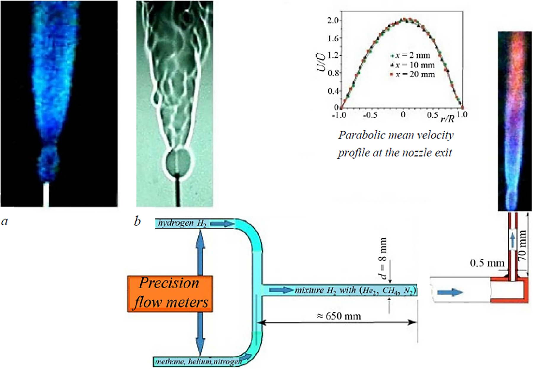
Figure 1: Experimental setup and flame images: (а)—directly recorded by the camera and (b)—shadowgraph pattern of diffusion combustion
The velocity U0 (m/s) of the hydrogen microjet measured at the nozzle exit was determined as U0 = Q/S, where Q (cm3/s) is the hydrogen flow rate and S (cm2) is the cross-sectional area of the micronozzle. Note that such a definition of the microjet velocity at transonic speeds seems to be not completely correct because a number of parameters including gas compressibility are not taken into account. Thus, the microjet velocity was also determined via the pressure difference ΔP (kgC/m2) at the inlet (Preducer) and outlet (Patmosphere) of the micronozzle (ΔP = Preducer − Patmosphere). Also, U0 (m/s) was taken as √ 2ΔP/ρ, where ρ (kg/m3) is the hydrogen density.
3.1 Combustion of Hydrogen and Methane Microjets
The shadowgraph patterns of diffusion combustion of a round hydrogen microjet are shown in Fig. 2 as functions of the flow rate Q and the jet velocity U0. As is seen, hydrogen combustion is associated with generation of a “bottleneck flame region” close to the nozzle exit, the phenomenon discussed earlier in [1]. A much different behavior is found in the case of a methane microjet. The flame becomes unstable and separates from the nozzle exit at U0 = 20 m/s with further termination of combustion at U0 = 25.5 m/s.
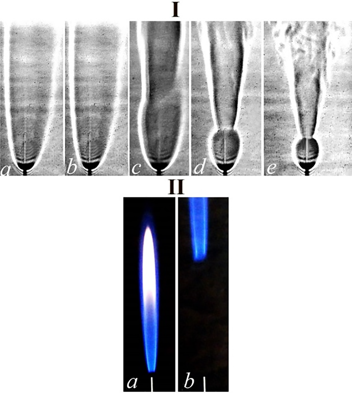
Figure 2: Diffusion combustion of a round hydrogen microjet vs. the flow rate Q (сm3/s) and microjet velocity U0 (m/s): a—20 (102), b—41 (204), c—61 (306), d—82 (408), e—102 (510), respectively—I and shadowgraph patterns of diffusion combustion of a round methane microjet: а—4 (20), b—5.1 (25.5)—II; the nozzle diameter is d = 0.5 mm
3.2 Diffusion Combustion of Hydrogen Mixed with Methane
The shadowgraph technique used in the present experiments allowed a detailed examination of the flame structure and its evolution. The flames of hydrogen and its mixture with methane were studied with variations of their flow rates, while keeping the total flow rate of QΣ = 20 cm3/s at U0 = 102 m/s, QΣ = 40 cm3/s at U0 = 204 m/s, QΣ = 60 cm3/s at U0 = 306 m/s, QΣ = 80 cm3/s at U0 = 408 m/s, and QΣ = 100 cm3/s at U0 = 510 m/s. Some illustrations are given below.
3.2.1 Combustion at U0 = 102 m/s
The results are shown in Fig. 3 and Table 1. In what follows, the ratio of the mass and volume flow rates of the gas components are marked by k = Mhydrogen/Mmethane, helium, nitrogen (mg/s/mg/s) and K = Qhydrogen/Qmethane, helium, nitrogen (cm3/s/cm3/s), respectively. At the flow rate QΣ = 20 cm3/s and microjet velocity U0 = 102 m/s, the laminar flame is observed in the entire range of the hydrogen/methane mass ratio k, while generation of a “bottleneck flame region” [1] is found only at k = 0.042 and, finally, combustion is terminated at k = 0.03.
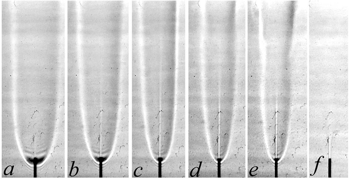
Figure 3: Shadowgraph patterns of diffusion combustion of a hydrogen microjet mixed with methane vs. the mass ratio k: а—hydrogen (1.8 mg/s), b—0.37, c—0.125, d—0.05, e—0.042, f—0.03 at U0 = 102 m/s; d = 0.5 mm

3.2.2 Combustion at U0 = 204 m/s
The results for this case are presented in Fig. 4 and Table 2. At the total flow rate QΣ = 40 cm3/s and jet velocity U0 = 204 m/s, the laminar jet and both laminar and turbulent flames are clearly seen in the interval k = 0.87 − 0.075, while generation of the “bottleneck flame region” [1] is observed starting from k = 0.87. The “bottleneck flame region” size goes down with diminution of the hydrogen/methane mass ratio, as it was found earlier in [1–4], as the microjet velocity increased.

Figure 4: Shadowgraph patterns of diffusion combustion of a hydrogen microjet mixed with methane vs. the mass ratio k: а—hydrogen (3.6 mg/s), b—0.87, c—0.38, d—0.36, e—0.21; f—0.19, g—0.126, h—0.075, i—0.074, j—0.071 at U0 = 204 m/s; d = 0.5 mm

One more aspect is separation of the turbulent flame from the nozzle exit. Combustion in the “bottleneck flame region” is observed at k = 0.126 − 0.075. In a narrow range about k = 0.075, both separation of the turbulent flame and combustion proceeding in the “bottleneck flame region” (Fig. 4h) are observed. Then, combustion of the turbulent jet is terminated, while keeping in the “bottleneck flame region” (Fig. 4i) and, finally, combustion ceases, as is shown in Fig. 4j.
3.2.3 Combustion at U0 = 306, 408, and 510 m/s
In these experimental regimes, the main features of combustion were the same as those described in Section 3.2.2 with variations of the parameter k. For more details, see Figs. 5 to 7 and Tables 3 to 5.

Figure 5: Shadowgraph patterns of diffusion combustion of a hydrogen microjet mixed with methane vs. the mass ratio k: а—hydrogen (5.4 mg/s), b—1.36, c—0.625, d—0.37, e—0.25, f—0.23, g—0.17, h—0.125 at U0 = 306 m/s; d = 0.5 mm

Figure 6: Shadowgraph patterns of diffusion combustion of a hydrogen microjet mixed with methane vs. the mass ratio k: а—hydrogen (7.2 mg/s), b—1.87, c—0.87, d—0.54, e—0.38, f—0.36, g—0.27, h—0.26 at U0 = 408 m/s; d = 0.5 mm
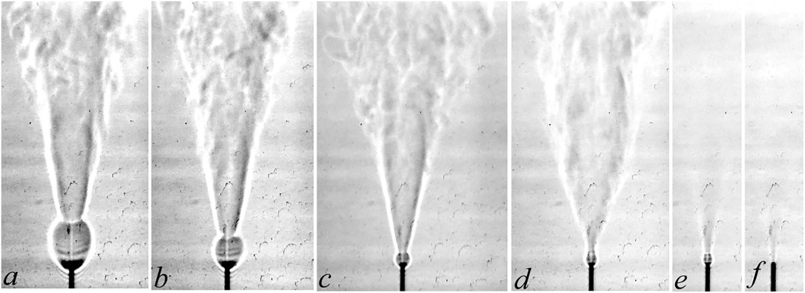
Figure 7: Shadowgraph patterns of diffusion combustion of a hydrogen microjet mixed with methane vs. the mass ratio k: а—hydrogen (9 mg/s), b—2.36, c—1.11, d—0.71, e—0.5, f—0.44 at U0 = 510 m/s; d = 0.5 mm


The results discussed above show that diffusion combustion of hydrogen/methane microjets is accompanied by generation of a “bottleneck flame region” close to the nozzle exit, as in the case of pure hydrogen microjets, see [1–4]. With increasing portion of methane and microjet velocity, the “bottleneck flame region” shrinks, similar to that observed in hydrogen combustion. The flame behaviors in both cases (hydrogen and hydrogen/methane combustion) seem to be much similar.
During diffusion combustion of a hydrogen microjet, gradual termination of combustion occurs with an increase in flow velocity. Several stages can be distinguished: separation of the turbulent flame from the nozzle exit in combustion sustaining in the “bottleneck flame region”; burning out of the turbulent portion of the microjet with combustion still proceeding in the “bottleneck flame region”; finally, complete termination of microjet burning. Combustion of a hydrogen/methane mixture is also terminated with increasing flow velocity; however, it depends on the volume (K) and mass (k) flow rates, see Table 6 and Fig. 8.

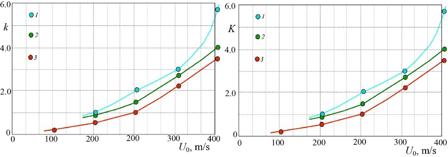
Figure 8: Variations of the mass ratio of a hydrogen/methane microjet (left) and their volumetric ratio (right) with the microjet velocity during diffusion combustion: 1—separation of the turbulent flame from the nozzle exit with combustion proceeding in the “bottleneck flame region”; 2—burning out of the turbulent jet with combustion still proceeding in the “bottleneck flame region”; 3—burning out of the microjet; d = 0.5 mm
One can see that the portion of hydrogen gets higher during diffusion combustion of a hydrogen/methane mixture with an increase in the microjet velocity. The variation of the “bottleneck flame region” size with the volume ratio of hydrogen/methane and microjet velocity is illustrated in Fig. 9. The “bottleneck flame region” gets smaller with increasing velocity of the microjet and diminution of the hydrogen fraction in the gas mixture.
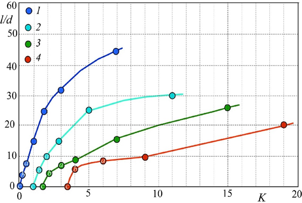
Figure 9: Variations of the size (l/d) of the “bottleneck flame region” with K for different microjet velocities: 1—204 m/s, 2—306 m/s, 3—408 m/s, 4—510 m s; a—separation of the turbulent flame from the nozzle exit during combustion sustaining in the “bottleneck flame region”; b—burning out of the turbulent jet with combustion proceeding in the “bottleneck flame region”; c—burning out of the microjet; d = 0.5 mm
Table 7 and Fig. 10 illustrate diffusion combustion of hydrogen and its mixture with methane in the presence of the “bottleneck flame region.”


Figure 10: Diffusion combustion of a round hydrogen/methane microjet depending on the mass ratio k: a—0.17; b—0.375; c—0,55; d—0.37; e—hydrogen; f—2; g—1; h—0.67; i—hydrogen; j—0.79; k—0.84 at the jet velocity a–k: 178, 204, 280, 306, 408, 434, 459, 485, 485, 561, and 587, respectively; d = 0.5 mm
Let us consider the “bottleneck flame region” during diffusion combustion of a hydrogen/methane mixture in a circular microjet with variations of the jet velocity U0 and mass ratio k (Figs. 11–14). One can see in Fig. 11 that the “bottleneck flame region” has a spherical shape; a laminar microjet is observed inside this region. Passing through a narrow region of a high density gradient, the microjet becomes turbulent [5], as is seen in Figs. 4 to 7. The above-mentioned phenomena, including a decrease of the “bottleneck flame region” size, were observed earlier in [1–4] during diffusion combustion of a hydrogen microjet.
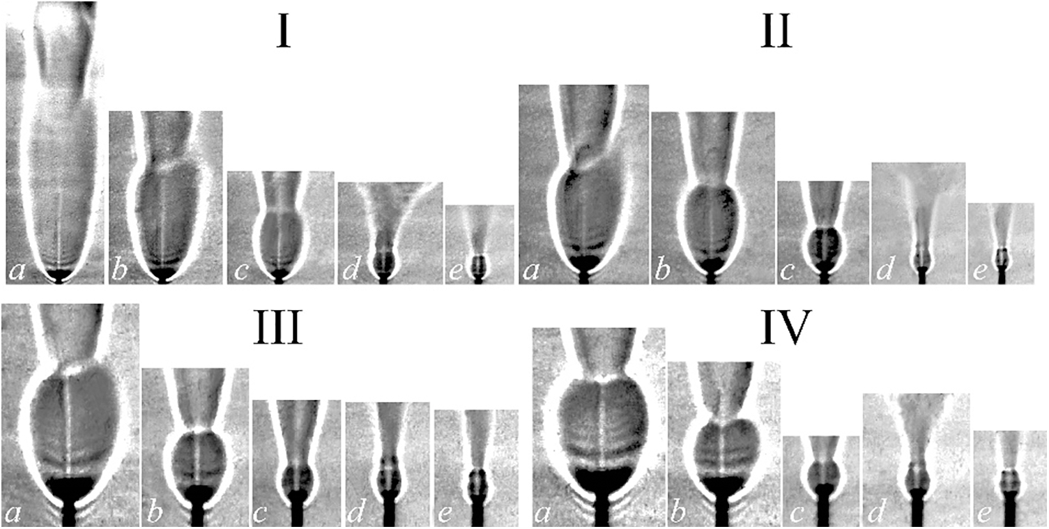
Figure 11: Shadowgraph patterns of the “bottleneck flame region” during diffusion combustion of a hydrogen/methane mixture vs. their mass ratio k: I: a—0.87; b—0.38; c—0.21; d—0.126; e—0.075 at U0 = 204 m/s; II: a—1.36; b—0.625; c—0.37; d—0.25; e—0.17 at U0 = 306 m/s; III: a—1.87; b—0.87; c—0.54; d—0.38; e—0.27 at U0 = 408 m/s; IV: a—hydrogen; b—2.36; c—1.11; d—0.71; e—0.5 at U0 = 510 m/s; d = 0.5 mm
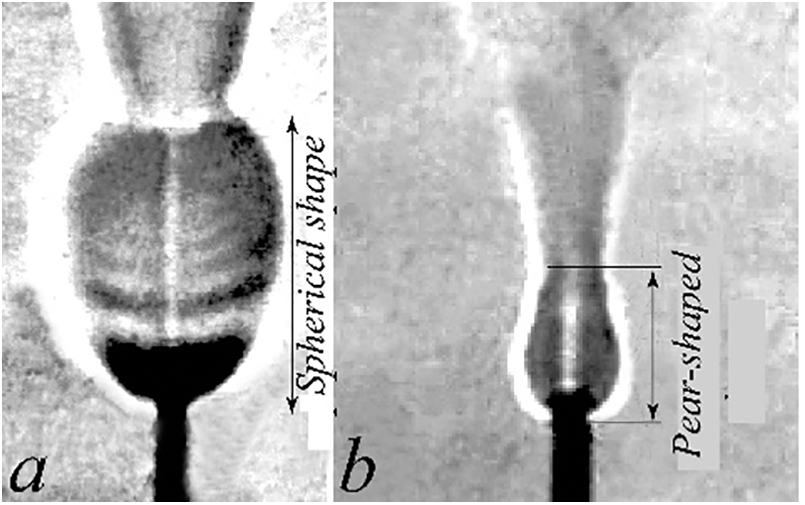
Figure 12: Shadowgraph patterns of the “bottleneck flame region” during diffusion combustion of pure hydrogen (a) and a hydrogen/methane mixture (b) at their mass ratio k = 0.5–0.71 at U0 = 510 m/s

Figure 13: Shadowgraph patterns of the “bottleneck flame region” during diffusion combustion of a hydrogen/methane mixture with variations of their mass ratio k: a—0.075–0.126 at U0 = 204 m/s; b—0.17–0.25 at U0 = 306 m/s; c—0.27–0.38 at U0 = 408 m/s; d—0.5–0.71 at U0 = 510 m/s; d = 0.5 mm
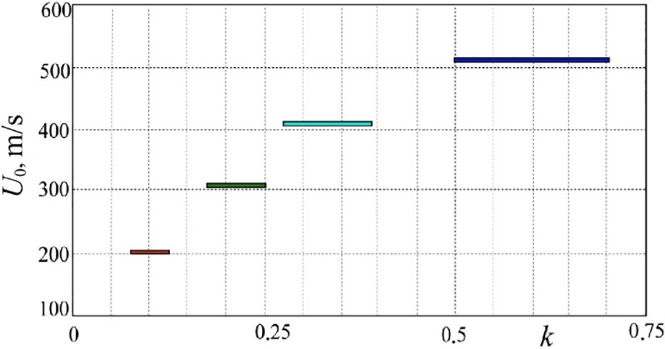
Figure 14: Ranges of pear-shaped “bottleneck flame region” generation with variations of the microjet velocity U0 and mass ratio k during diffusion combustion of a round hydrogen/methane microjet; d = 0.5 mm
Concerning diffusion combustion of a hydrogen/methane mixture, a decrease in the fraction of hydrogen, see Fig. 11, and transformation of the spherical “bottleneck flame region” to a pear-shaped configuration occur in combustion with the smallest portion of hydrogen, see Figs. 12 and 13. Then, Fig. 14 shows that the variation of hydrogen fraction gets wider with an increase in the microjet velocity, so that the flame transforms to a pear-shaped shape.
3.3 Diffusion Combustion of Hydrogen Mixed with Helium
Experiments on the microjet combustion of hydrogen mixed with helium were carried out with the same technique used in the previous section. The flame evolution was studied with variations of the flow rates of the gas components and flow velocity. Some results are shown in Fig. 15 and Table 8. One can observe the presence of the “bottleneck flame region” with a laminar flame and a high density gradient at its border. Further downstream, the microjet becomes turbulent. Over the entire range of k, a “bottleneck flame region” is found to form during diffusion combustion of a hydrogen microjet. Further, with increasing microjet velocity and diminution/growth of the hydrogen/helium fractions, the “bottleneck flame region” becomes smaller. We conclude that diffusion combustion of the hydrogen/helium microjet looks similar to that of the hydrogen/methane mixture presented above as well as to pure hydrogen combustion discussed in [1–4].

Figure 15: Shadowgraph patterns of diffusion combustion of a hydrogen/helium mixture vs. k: а—hydrogen (50 mg/s), mixtures of hydrogen and helium at b—1.7, c—1.25, d—0.9, e—0.6, f—0.49; microjet velocity U0, m/s: а–f corresponding to 255, 332, 357, 398, 469, and 505, respectively; d = 0.5 mm

One more illustration of diffusion combustion of hydrogen and its mixtures with helium is presented in Table 9 and Fig. 16. Here, the mass flow rate of hydrogen is kept constant at 4.5 mg/s and that of helium varies from 2.7 to 8.9 mg/s. It is seen that the “bottleneck flame region” is retained with an increase in the microjet velocity and growth of the helium fraction in the mixture; however, its size decreases. This section of the flow with a laminar microjet is shown in more detail in Fig. 17.

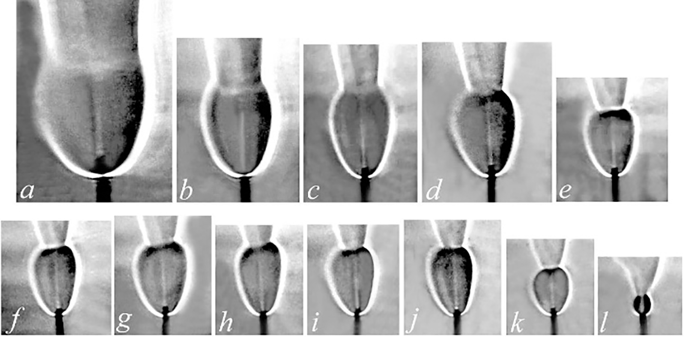
Figure 16: Shadowgraph patterns of diffusion combustion of a hydrogen/helium mixture vs. k: а—hydrogen (4.5 mg/s), mixtures of hydrogen and helium at b—1.7, c—1.14, d—1.25, e—0.9, f—0.6, g—0.9, h—0.55, i—1.08, j—0.49, k—0.98, l—12.4; microjet velocity U0, m/s: a–l corresponding to 255, 332, 337, 357, 362, 469, 398, 423, 449, 505, 541, and 663, respectively; d = 0.5 mm
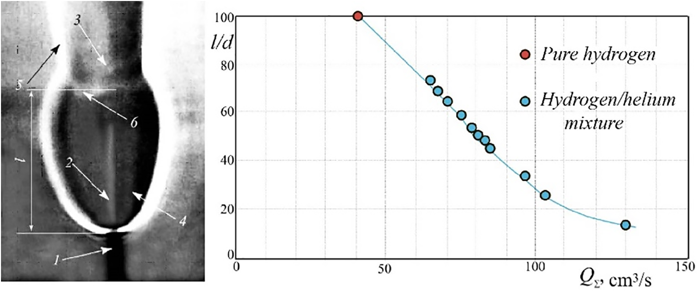
Figure 17: Variation of the “bottleneck flame region” size during diffusion combustion of a hydrogen/helium mixture in a round microjet at d = 0.5 mm with the gas flow rate QΣ (right) and shadowgraph pattern of combustion: 1—micronozzle, 2—laminar jet, 3—turbulent jet, 4—“bottleneck flame region,” 5—flame of the turbulent microjet, 6—combustion front of the “bottleneck flame region,” l—length of the “bottleneck flame region” (left)
The size of the “bottleneck flame region” goes down both with an increase in the flow rate and at variation of the hydrogen/helium mass ratio k, which was shown above and found earlier in [1–4] in the case of diffusion combustion of hydrogen microjets. To make clear the origination of the “bottleneck flame region,” the combustion process was examined with different fractions of the gas components in the mixture. It was found that the helium additive does not lead to a pronounced variation of combustion of the methane/helium mixture as compared to pure methane combustion. In particular, it does not affect flameout from the nozzle exit and generation of the “bottleneck flame region.”
During these experiments, our idea was to verify an assumption that, with addition of helium diffusing into surrounding air, a portion of methane entrains helium. As a result, a flow region forms near the nozzle exit with a sufficient fuel concentration to sustain a spherical attached flame stabilizing combustion of the entire microjet. However, the expected effect of helium additives was not observed. This may be due to weak entrainment of helium by methane in the direction radial to the microjet axis. As helium, unlike hydrogen, does not support combustion, its addition to methane does not affect the conditions of “bottleneck flame region” generation and flameout from the nozzle exit.
3.4 Diffusion Combustion of Hydrogen Mixed with Nitrogen
Research data on combustion of hydrogen microjets mixed with nitrogen are presented in the tables and graphs below. In Fig. 18, one can see that the main features of hydrogen/nitrogen diffusion combustion, including generation of the “bottleneck flame region” and its behavior with variation of flow velocity and the fractions of gas components in the mixture (Table 10), remain the same as those described in Sections 3.2 and 3.3. In addition, they are similar to the events observed in combustion of pure hydrogen microjets.
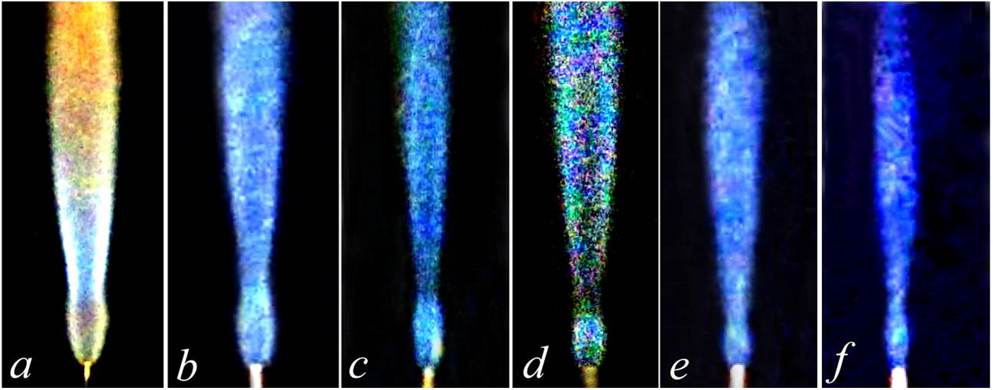
Figure 18: Diffusion combustion of a hydrogen/nitrogen mixture vs. their mass ratio k: a—hydrogen (4.5 mg/s), b—0.26, c—0.24, d—0.21, e—0.15, f—0.08; microjet velocity U0, m/s: a–f corresponding to 255, 326, 332, 342, 316, and 296, respectively (f—flameout); d = 0.5 mm

Further illustrations on combustion of gas mixtures are presented in Tables 11 and 12, see also Fig. 19. It is found that the “bottleneck flame region” is sustained with an increase in the microjet velocity and growth of gas additives to the mixture.


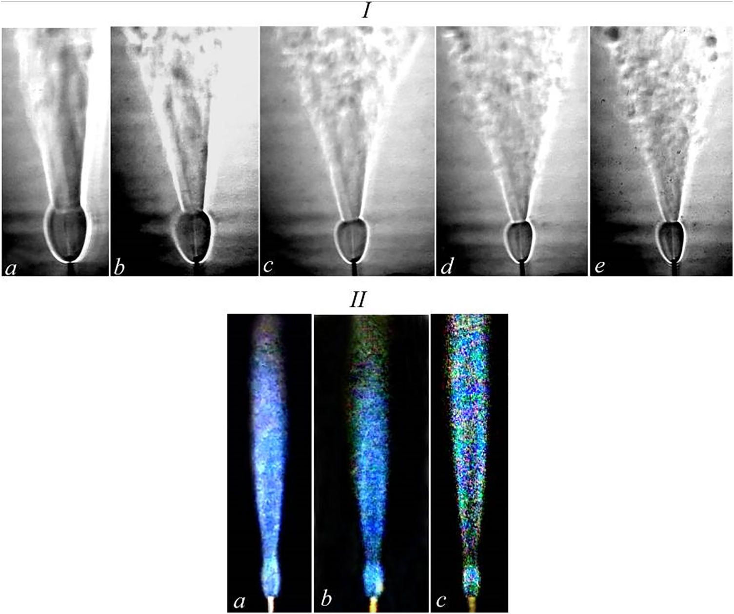
Figure 19: Shadowgraph patterns on diffusion combustion of a round hydrogen/helium microjet vs. k: a—1.7; b—1.25; c—0.9; d—0.6; e—0.49 and the microjet velocity U0, m/s: а–e corresponding to 332, 357, 398, 469, and 505, respectively—I. Flow patterns of diffusion combustion of a hydrogen/nitrogen mixture vs. k: a—0.26; b—0.24; c—0.21 and the microjet velocity U0, m/s: а–с corresponding to 326, 332, and 342, respectively—II. d = 0.5 mm, the mass flow rate of hydrogen is 4.5 mg/s with variations of the mass flow rates of other gas additives
Fig. 20 shows the total (QΣ) and fractional (Q) gas flow rates of hydrogen and its mixture with methane during diffusion combustion of a round microjet with variations of flow velocity. Here, symbol “1” illustrates the decrease in the “bottleneck flame region” size (l/d) depending on the volume ratio of the gas mixture and on the microjet velocity. With increasing flow velocity, the fraction of hydrogen getting higher and the fraction of methane going down, the size of the “bottleneck flame region” is reduced. See Fig. 21 for more details on the behavior of the hydrogen/methane mixture.
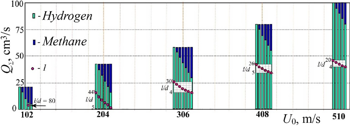
Figure 20: Behavior of the total QΣ and fractional Q volumetric flow rates of hydrogen and its mixture with methane during diffusion combustion of a round microjet with variations of flow velocity. The reduction of the “bottleneck flame region” l/d depending on the volume ratio of the gas mixture and microjet velocity is marked by “1”
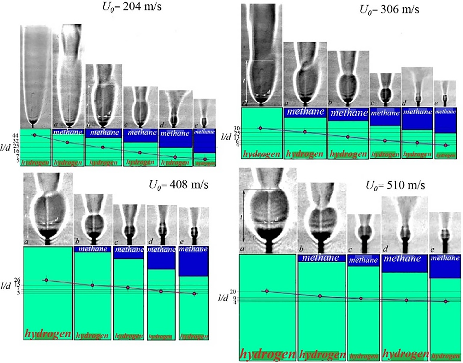
Figure 21: Total QΣ and fractional Q volumetric flow rates of hydrogen and its mixture with methane during diffusion combustion of a round microjet under conditions of different flow velocities; the shadowgraph patterns make clear the evolution of the “bottleneck flame region”
We emphasize that the evolution of the “bottleneck flame region” close to the nozzle exit depends both on the microjet velocity and on the portion of hydrogen/methane in the mixture. As the fraction of methane increases, the “bottleneck flame region” size is obviously reduced.
To sum up, the following key points are to be noticed:
The evolution of the microjet and flame during diffusion combustion of hydrogen mixtures with methane, helium, and nitrogen is associated with formation of a “bottleneck flame region” close to the nozzle exit similar to that in combustion of pure hydrogen.
The “bottleneck flame region” has a spherical shape representing the laminar portion of the microjet. The flow instantly becomes turbulent after passing through a narrow layer of a high density gradient at the border of this region.
One can distinguish several stages of diffusion combustion of the hydrogen/methane mixture. These are separation of the flame from the nozzle exit with combustion sustaining in the “bottleneck flame region,” flameout with the microjet still burning in the “bottleneck flame region,” and, finally, termination of combustion. These observations correlate with the behavior of hydrogen microjets. The above-mentioned stages of hydrogen/methane mixture combustion are found in the range of flow velocities from 200 to 500 m/s; in the case of hydrogen microjets, they occur at 600 to 800 m/s.
Combustion of the mixture of hydrogen and methane is more stable than that of the pure methane microjet. Thus, stable turbulent combustion of methane can be achieved with hydrogen additives. To make combustion of hydrogen mixed with methane, helium, and nitrogen in a round microjet more stable, one needs to increase the portion of hydrogen.
In this study, information was obtained for the first time about the influence of methane, helium and nitrogen additives on the limits of stable combustion of microjets of hydrogen mixtures with these gases, which is of practical importance from the point of view of fire and explosion safety for hydrogen energy.
Acknowledgement: Not applicable.
Funding Statement: The work was carried out with the financial support of the Ministry of Science and Higher Education of the Russian Federation, Agreement dated 24.04.2024, No. 075-15-2024-543.
Author Contributions: The authors confirm contribution to the paper as follows: study conception and design: Victor Kozlov; data collection: Yuriy Litvinenko, Andrey Shmakov, Alexander Pavlenko; analysis and interpretation of results: Victor Kozlov, Andrey Shmakov, Yuriy Litvinenko, Alexander Pavlenko; draft manuscript preparation: Victor Kozlov, Alexander Pavlenko. All authors reviewed the results and approved the final version of the manuscript.
Availability of Data and Materials: There is no unavailable data in this study.
Ethics Approval: Not applicable.
Conflicts of Interest: The authors declare no conflicts of interest to report regarding the present study.
References
1. Kozlov VV, Grek GR, Korobeinichev OP, Litvinenko YuA, Shmakov AG. Features of the hydrogen combustion in the round and plane microjet in a transverse acoustic field and their comparison with results of the propane combustion under the same conditions. NSU Newslett Series: Phys. 2014;9(1):79–86 (In Russian). [Google Scholar]
2. Shmakov AG, Grek GR, Kozlov VV, Korobeinichev OP, Litvinenko YuA. Different behaviors of diffusion combustion of the hydrogen round jet in air. NSU Newslett Series: Phys. 2015;10(2):27–41 (In Russian). [Google Scholar]
3. Grek GR, Korobeinichev OP, Litvinenko YA, Kozlov VV, Shmakov AG. Combustion of the hydrogen high-speed microjet efflux into the air. In: Collection of Abstracts of Reports of the All-Russian Scientific and Technical Conference Aircraft Engines of the 21st Century, 2015; Moscow, Russia (In Russian). [Google Scholar]
4. Grek GR, Katasonov MM, Kozlov VV, Litvinenko MV. Diffusion combustion of the hydrogen (round beveled nozzle). NSU Newslett Series: Phy. 2015;10:42–51 (In Russian). [Google Scholar]
5. Agrawal AK, Albers BW, Alammar KHN. Effects of buoyancy on transitional hydrogen gas—Jet diffusion flames. Combust Sci Technol. 2005;177(2):305–22. doi:10.1080/00102200590900480. [Google Scholar] [CrossRef]
6. Annushkin YUM, Sverdlov ED. Stability of submerged diffusion flames in Subsonic and underexpanded supersonic gas-fuel streams. Combust Explos Shock Waves. 1978;14(5):597–605. doi:10.1007/BF00789718. [Google Scholar] [CrossRef]
7. Mogi T, Horiguchi S. Experimental study on the hazards of high-pressure hydrogen jet diffusion flames. J Loss Prev Process Ind. 2009;22(1):45–51. doi:10.1016/j.jlp.2008.08.006. [Google Scholar] [CrossRef]
8. Rudy W, Dabkowski A, Teodorczyk A. Experimental and numerical study on spontaneous ignition of hydrogen and hydrogen-methane jets in air. Int J Hydrogen Energy. 2014;39(35):20388–95. doi:10.1016/j.ijhydene.2014.05.077. [Google Scholar] [CrossRef]
9. Gao J, Hossain A, Nakamura Y. Flame base structures of micro-jet hydrogen/methane diffusion flames. Proc Combust Inst. 2017;36(3):4209–16. doi:10.1016/j.proci.2016.08.034. [Google Scholar] [CrossRef]
10. Li L, Yuan Z, Xiang Y, Fan A. Numerical investigation on mixing performance and diffusion combustion characteristics of H2 and air in planar micro-combustor. Int J Hydrogen Energy. 2018;43(27):12491–8. doi:10.1016/j.ijhydene.2018.04.194. [Google Scholar] [CrossRef]
11. Torii S. Combustion and thermal transport characteristics of subsonic hydrogen jet diffusion flame by means of ion-current method. Int J Energy Res. 2011;35(1):40–3. doi:10.1002/er.1756. [Google Scholar] [CrossRef]
12. Zhang J, Li X, Yang H, Jiang L, Wang X, Zhao D. Study on the combustion characteristics of non-premixed hydrogen micro-jet flame and the thermal interaction with solid micro tube. Int J Hydrogen Energy. 2017;42(6):3853–62. doi:10.1016/j.ijhydene.2016.07.255. [Google Scholar] [CrossRef]
13. Brennan S, Molkov V. Pressure peaking phenomenon for indoor hydrogen releases. Int J Hydrogen Energy. 2018;43(39):18530–41. doi:10.1016/j.ijhydene.2018.08.096. [Google Scholar] [CrossRef]
14. Hussein H, Brennan S, Molkov V. Dispersion of hydrogen release in a naturally ventilated covered car park. Int J Hydrogen Energy. 2020;45(43):23882–97. [Google Scholar]
15. Kazemi M, Brennan S, Molkov V. Hydrogen safety by design: exclusion of flame blow-out from a TPRD. Hydrogen. 2024;5(2):280–92. [Google Scholar]
16. Resende PR, Ayoobi M, Afonso AM. Numerical investigations of micro-scale diffusion combustion: a brief review. Appl Sci. 2019;9(16):3356. [Google Scholar]
17. Kang X, Sun B, Wang J, Wang Y. A numerical investigation on the thermo-chemical structures of methane-oxygen diffusion flame-streets in a microchannel. Combust Flame. 2019;206:266–81. [Google Scholar]
18. Zhao M, Liu L, Fan A. Comparison of combustion efficiency of micro hydrogen jet flames confined in cylindrical tubes of different diameters. Chem Eng Process-Process Intensif. 2020;153:108000. [Google Scholar]
19. Stewart JR. CFD modelling of underexpanded hydrogen jets exiting rectangular shaped openings. Process Saf Environ Prot. 2020;139(3):283–96. doi:10.1016/j.psep.2020.04.043. [Google Scholar] [CrossRef]
20. Liu L, Zhao M, Chen Y-K, Fan A-W, Li D. A numerical investigation in buoyancy effects on micro jet diffusion flame. J Cent South Univ. 2020;27(3):867–75. doi:10.1007/s11771-020-4337-7. [Google Scholar] [CrossRef]
21. Zhao M, Fan A. Buoyancy effects on hydrogen diffusion flames confined in a small tube. Int J Hydrogen Energy. 2020;45(38):19926–35. doi:10.1016/j.ijhydene.2020.05.010. [Google Scholar] [CrossRef]
22. Li D, Wang R, Yang G, Wan J. Effect of hydrogen addition on the structure and stabilization of a micro-jet methane diffusion flame. Int J Hydrogen Energy. 2021;46(7):5790–8. doi:10.1016/j.ijhydene.2020.11.034. [Google Scholar] [CrossRef]
23. Barabás J, Jovicic V, Delgado A. Simulation of a hydrogen-air diffusion flame under consideration of component-specific diffusivities. Appl Sci. 2022;12(6):3138. doi:10.3390/app12063138. [Google Scholar] [CrossRef]
24. Anaclerio G, Capurso T, Torresi M. Gas-dynamic and mixing analysis of under-expanded hydrogen jets: effect of the cross section shape. J Fluid Mech. 2023;970:A8. [Google Scholar]
25. Hossain A, Nakamura Y. Thermal and chemical structures formed in the micro burner of miniaturized hydrogen-air jet flames. Proc Combust Inst. 2015;35:3413–20. [Google Scholar]
26. Shmakov AG, Kozlov VV, Litvinenko YA, Pavlenko AM. Specific features of the flame structure of a pre-mixed hydrogen-oxygen mixture exhausting into air. Int J Hydr Energy. 2024;74:121–7. [Google Scholar]
27. Mohammadpour J, Salehi F. A computational analysis of cryogenic hydrogen release under various conditions. Int J Hydrogen Energy. 2024;56:676–89. [Google Scholar]
28. Shen J, Zou X, Zhang A, Zhang K, Gao W. Study on high-pressure hydrogen leakage characteristics under different shapes of nozzles. Int J Hydrogen Energy. 2024;73:619–31. [Google Scholar]
29. Wang K, Li C, Jia W, Chen Y, Wang J. Under-expanded jet and diffusion characteristics for small-hole leakage of hydrogen-blended natural gas in high-pressure pipelines. Process Saf Environ Prot. 2024; 190(5–6):195–211. doi:10.1016/j.psep.2024.07.045. [Google Scholar] [CrossRef]
30. Rosado D, Mendiburu A, Machin E, Pedroso D, Carvalho J. Theoretical study of the expansion of Roper’s theory on the laminar jet diffusion flame length in 2D and 3D in natural gas and hydrogen mixtures. Int J Hydrogen Energy. 2024;77:1352–74. doi:10.1016/j.ijhydene.2024.06.277. [Google Scholar] [CrossRef]
31. Li H, Li M, Chu G, Xiao H. Experimental investigation and model analysis of non-premixed hydrogen jet flames. Int J Hydrogen Energy. 2024;44:28316. doi:10.1016/j.ijhydene.2024.01.143. [Google Scholar] [CrossRef]
32. Liu G, Wu Y. Lift-off height model of hydrogen autoignited flame in turbulent hot air coflow. Int J Hydrogen Energy. 2024;49(2):401–12. doi:10.1016/j.ijhydene.2023.08.099. [Google Scholar] [CrossRef]
Cite This Article
 Copyright © 2024 The Author(s). Published by Tech Science Press.
This work is licensed under a Creative Commons Attribution 4.0 International License , which permits unrestricted use, distribution, and reproduction in any medium, provided the original work is properly cited.


 Submit a Paper
 Propose a Special lssue
 View Full Text
 Download PDF
 Downloads
 Citation Tools