 Open Access
ARTICLE
Analysis of Air Exchange System Influence on Thermal and Concentration Modes in the Local Working Area under Radiant Heating Conditions
School of Earth Sciences & Engineering, National Research Tomsk Polytechnic University, Tomsk, 634050, Russia
* Corresponding Author: Vyacheslav Maksimov. Email:
(This article belongs to the Special Issue: Heat and Mass Transfer in Energy Equipment)
Frontiers in Heat and Mass Transfer 2024, 22(6), 1597-1612. https://doi.org/10.32604/fhmt.2024.056758
Received 30 July 2024; Accepted 10 October 2024; Issue published 19 December 2024
Abstract
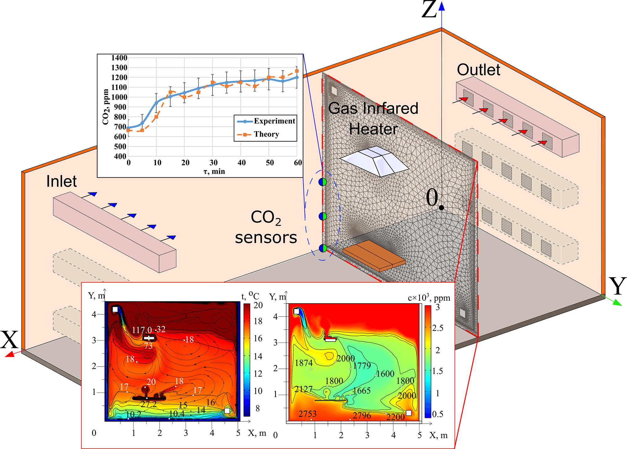
One of the effective options for energy saving in terms of heat costs for the formation of routine thermal conditions of working areas of large-sized industrial premises is the replacement of traditional convective (water) heating systems with systems, the main part of which are gas infrared emitters. But the mass introduction of such systems based on emitters was held back until recently by the lack of scientific and technical foundations for ensuring not only the routine thermal conditions of local working areas, but also ensuring acceptable concentrations of carbon dioxide, which is formed during the operation of a gas emitter. Solving the latter problem by the method of experimental selection of heating and air exchange modes is practically impossible due to the multivariate nature of possible solutions to this problem. Therefore, the purpose of the work is to analyze the results of theoretical studies of the possibility of ensuring an acceptable level of carbon dioxide concentrations in local working areas during the operation of gas infrared emitters and an air exchange system. Numerical modeling of heat and mass transfer processes under such conditions was performed in a fairly wide range of the main significant factors: air flow rate in the air exchange system from 0.01 to 0.04 kg/s, the position of the air inlet and outlet channels relative to the radiator and the local workplace (height from 0.3 to 4.1 m). It was found that by varying the numerical values of these factors, it is possible to ensure carbon dioxide concentrations in the local working area within the permissible limits of up to 1400 ppm.Graphic Abstract
Keywords
The comfort of working conditions in local working areas of large-sized premises [1–4] when using gas infrared heaters (GIH) as heating sources [5,6] is assessed based on air temperature and concentration of harmful substances [7,8]. The formation of temperature and gas concentration fields is carried out as a result of three interrelated processes that determine the transfer of heat [4] and anthropogenic oxides [9,10] formed during the GIH operation. These processes include the heat transfer by radiation from the radiating surface of the GIH to the surfaces of enclosing structures and equipment, mixed convection in unevenly heated air and forced convection as a result of the air exchange system operation, the transfer of heat and contaminants as a result of mixed convection and diffusion. Molecular diffusion is a relatively slow process and the CO2 spread is mainly accomplished by convection [11,12]. The need for an air exchange system to ensure air movement during a light-type GIH operation [2,13] is explained by the direct entry of combustion products into the air [9,14]. It was previously established that when a gas infrared heater is operating, the air heated by it rises to the upper part of the room [15,16]. The operation of an air exchange system makes it is possible to direct the heated air into the local working area in order to increase the air temperature in it [9,10]. However, this heated air is contaminated with combustion products of natural gas (mainly CO2). The direction of such air into the local working area, where the worker is located, leads to an increase in the concentration of carbon dioxide in it. In this case, a significant excess of the standard values is possible. According to [7,8], the average shift value of CO2 concentration in the air for rooms, where people are located, should not exceed 1400 ppm (Table 1).

Also, experimental studies have shown [17] that short-term CO2 exposure, starting at 1000 ppm, affects cognitive abilities, including decision making and problem solving [18,19], increased heart rate, change in heart rate variability, increased blood pressure, increased peripheral blood circulation [20,21], dizziness and headache [22]—which is not comfortable for a people.
An assessment of the carbon dioxide concentration in the local working area due to the flow of air heated by the GIH in it (during operation of the air exchange system) has not been conducted yet.
Previously, studies of heat and mass transfer processes in a heating system with an operating gas radiator, but without forced air exchange in the local working zone were conducted [15,23]. Experiments and results of mathematical modeling [23–25] showed that under conditions of free convection in any heating mode, the concentration of carbon dioxide in the local working zone exceeds the maximum permissible concentrations. The results [13,24] substantiated the need to use a forced air exchange system under operating conditions of gas radiators.
It should also be noted that a comparison of previously obtained experimental data [15,24,25] and the results of numerical modeling [15,25] within the framework of a two-dimensional (flat) model of non-stationary heat and mass transfer in the local working zone and its vicinity showed their good agreement. That is, the influence of transfer processes along the third coordinate (which were implemented in the experiments [15]) on the air temperature in the local working zone is insignificant. Accordingly, there are objective grounds for using a two-dimensional (flat) mathematical model of thermophysical and hydrodynamic processes in the local working zone in mathematical modeling. But the results [15] were obtained for thermogravitational convection modes. Therefore, the use of the modeling results [15] for the analysis of the regularities of mass and heat transfer processes under mixed convection conditions (during operation of the air exchange system) is not yet justified.
The aim of this study was the mathematical modeling of temperature and concentration in local working areas of the premises during operation of heating systems based on the GIH and air exchange system, as well as the analysis of the influence of the location of fresh air inlet and outlet channels on the CO2 temperature and concentration in order to assess the possibility of achieving regulated comfort conditions for the worker. An assessment based on the results of theoretical analysis of the possibility of achieving the regulatory conditions of comfort for the worker is necessary due to the fact that obtaining reliable information on the temperatures and concentrations of carbon dioxide in local working zones based on the results of experimental studies is a very complex and labor-intensive task under mixed convection conditions. The studies [15,16,23–25] have shown that if under conditions of free (thermogravitational) convection the main patterns of heat and mass transfer in local working zones during operation of gas infrared emitters can be established with moderate time expenditures (all process characteristics change monotonically when varying the main significant factors), then under conditions of mixed convection (during operation of the air exchange system) these characteristics in typical sections of the local working zone (temperature, gas velocity, carbon dioxide concentration) change non-monotonically. The reason is the influence of two factors (temperature gradients and pressure differences in this zone) whose consequences are essentially opposite—the force of thermogravitational convection initiates the movement of all gases, including carbon dioxide, upward, and the forced movement of “fresh” air from the air exchange system downward. Therefore, both solutions acceptable for practice and unacceptable ones are possible. But in experiments, it is almost impossible to establish this without preliminary theoretical analysis.
2 Mathematical Formulation of the Problem and Solution Method
The room under consideration was a closed rectangular area with an air atmosphere (Fig. 1). A gas infrared heater (1), a horizontal panel (simulating equipment, 2) and air inlet and outlet areas of the air exchange system (3, 4) were located in the considered room.
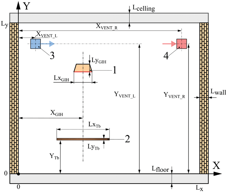
Figure 1: Problem solution area: 1—GIH, 2—panel, 3—air inlet area, 4—air outlet area
The solution area of the problem is selected based on possible practical applications of the modeling results. In this regard, it should be noted that the development of all industries leads to a significant decrease in the number of workers in the implementation of all modern technological processes. Even with the conveyor assembly of complex machines and devices, the number of workers on the conveyors decreases due to the use of various kinds of robotic complexes. But even under the conditions of operation of an automated and highly robotic conveyor, personnel is required in individual local sections of the conveyor line. In this case, there is no need to ensure a scheduled thermal regime over the area of the entire production cycle—it is enough to ensure such modes of local workplaces. Fig. 1 shows a fairly typical interpretation of a real production workplace near a running conveyor, the direction of which is perpendicular to the plane of the drawing. Local workplaces in a real situation can be either to the left or to the right of the panel simulating the cross-section of the conveyor belt.
The numerical analysis was carried out for a room with dimensions of 10 m × 5 m × 4.4 m. A rectangular area with dimensions Lx × Ly = 5 × 4.4 m was allocated for two-dimensional modeling. The room was limited by the floor, walls and ceiling. The lower left corner of the room was chosen as the starting point. The gas infrared heater (with the dimensions of LxGIH = 0.4 m and LyGIH = 0.05 m) and the horizontal panel (with the dimensions of Lxtb = 0.6 m and Lytb = 0.04 m) were placed in the room. The inlet and outlet channels of the air exchange system had the coordinates of XVENT_L, YVENT_L, XVENT_R, YVENT_R. The enclosing structures were made of concrete (Lcelling, = Lfloor, = Lwall = 0.1 m, ρ = 2500 kg m−3, c = 840 J kg−1 K−1, λ = 1.55 W K−1 m−1, ε = 0.95) [20,21]. The panel was made of wood (ρ = 520 kg m−3, c = 2300 J kg−1 K−1, λ = 0.15 W K−1 m−1, ε = 0.5) [26,27]. The GIH had power of 5 kW and used a propane (C3H8). The initial temperature was taken to be 7°C, the temperature of the incoming air from the air exchange system was equal to 7°C, and the concentration of carbon dioxide was 400 ppm. The flow rate of the air exchange system Gvent varied in the range from 0.01 to 0.2 kg/s (4.55–90.9)·10−5 kg/(s·m3).
The implementation of the numerical solution of heat and mass transfer equations was carried out similarly to [15] in the COMSOL Multiphysics environment. This software provides the use of various modules for describing interconnected physical processes and coordinating their operation using multiphysical modeling tools, libraries of thermophysical properties of materials, tools for automatically constructing a computational grid, as well as tools for visualizing calculation results [28].
When setting the problem, the conditions that must be ensured in production facilities of most countries of the world community were adopted. First, the air must not contain particles of any condensed substances (dust), which could absorb and scatter the radiation generated by the gas infrared emitter when using gas emitters. That is, the air is accepted in accordance with industrial safety and sanitation standards as transparent for infrared radiation. Second, the humidity must not exceed the standard values (60%) [29,30]. That is, there must not be excess water vapor in the air, which can also absorb and scatter the radiation of the gas infrared emitter.
A notable feature of the process of heating the air of the production facility during the operation of the gas infrared emitter is that the radiation does not directly heat the air. The radiation heats the enclosing structures (this has been established in numerous experiments [15,24]), which then give off heat to the air as a result of conduction and convection processes. This physical model established in the experiments was the basis for the formulated mathematical model of the processes of heat and mass transfer in the local working area, occurring as a result of the operation of the gas infrared emitter.
Thermal radiation flows between a closed system of radiating gray surfaces of solid objects were calculated within the framework of a zone model (radiating surfaces were divided into finite components (“zones”) with a constant temperature) with the determination of average angular coefficients and resulting flows by the Saldo method using the “Surface-to-Surface Radiation” software module. The air atmosphere between the radiating surfaces was considered as a diathermic (absolutely transparent for thermal radiation) medium. Heating systems are used in the cold season, which is usually accompanied by low humidity values. Therefore, in this study, the influence of air humidity on the heat and mass transfer process is neglected.
The parameters of convective-conductive heat transfer were determined in the software module “The Heat Transfer in Fluids” by solving the energy Eq. (1):
In addition to time (τ), the equation uses the values of density (ρ), temperature (T), specific isobaric heat capacity (cp) and thermal conductivity (λ).
Integration of Eqs. (2) and (3) to determine the velocity field,
where
In Eq. (2), the viscous stress tensor (
Solutions of Eqs. (4) and (5) were used to calculate
Within its framework, the radiating surfaces are divided into finite isothermal components-“zones”. For each zone, the integral densities of the incident (Ψ) and effective (Ω) heat fluxes are formulated, which are related by the relationship (6):
where
The software module “Transport of Concentrated Species” was used to determine the CO2 concentration in the air. The assumption was made about the binarity of the diffusion process in the system “air without carbon dioxide–carbon dioxide” within the framework of the Fick model [32] together with the convective transfer of CO2 in accordance with the relations:
The system of Eqs. (7)–(10) use the mass and molar concentrations (
After analyzing the literature [35] and taking into account the dependence of γ on the temperature range, the value γ = 1.70 was chosen for the calculations (11).
At the initial moment of time, a thermodynamic equilibrium in still air was assumed: equality of temperatures T0 and mass fraction CO2 (
Adiabatic conditions were set for the external surfaces of enclosing structures, since due to their thickness, as a rule, walls and ceilings do not have time to change the temperature of their external surface during a work shift.
The heat flow from the GIH is divided into the heat flow of radiation (proportional to the radiant efficiency
The traditional no-slip conditions for the system of Eqs. (2) and (3) at the “gas-solid surface boundaries” were supplemented by the use of the wall function method in this region of predominance of viscous effects over turbulent ones.
The value of the mass flow rate of the incoming air was used to determine the normal rate of the air flow through surface of the device (3) in Fig. 1, and on the surface of the device (4) of the same figure, through which air is removed from the room, the pressure level, which is determined by the value of the atmospheric pressure outside the room, is set as a boundary condition.
The mass flow of CO2 emitted as a result of combustion of natural gas was set in the upper boundary of the GIH:
As in previous calculations [15,16], internal convergence of solutions was achieved by using the Mesh grid construction procedure.
To obtain a solution independent of the grid size, an analysis of the influence of the non-uniform grid parameters on the main results was performed. Three grid options with different numbers of nodes and, accordingly, with the maximum and minimum cell sizes were considered (Table 2).

Analysis of the results (Fig. 2a) shows that increasing the number of nodes from 6670 (option 1 (Coarse)) to 9143 (option 2 (Normal)) leads to a small deviation in the values of CO2 concentrations (about 100 ppm (8.3%)) in the most informative section.
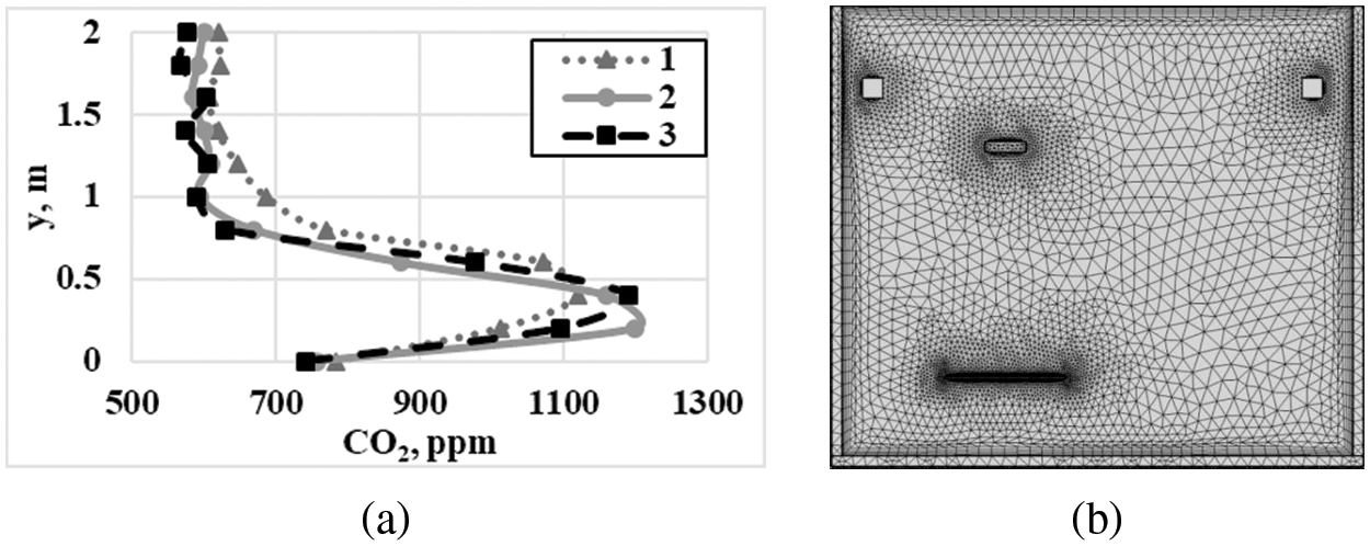
Figure 2: Distribution of carbon dioxide concentrations (a) in the section y = 2.4 m: 1–3 grid options in accordance with the Table 2 and grid division of the solution area; (b) grid option 2. Supply air flow rate is 0.01 kg/s, time is 60 min
A further increase in the number of cells to 18,590 (option 3 (Fine)) is impractical, since the deviation in CO2 concentrations is insignificant (less than 30 ppm (0.25%)). Therefore, a grid with a number of nodes of 9143 (Fig. 2b) can be used to save the calculation time.
Experimental studies were also conducted to determine the temperatures, structures and values of air movement speeds and carbon dioxide concentrations in the local working area of the production room, emitted by a gas infrared emitter during combustion of propane petroleum gas in it. For this purpose, a room with dimensions of 5 × 4.4 × 11 m was used (Fig. 3). As a source of infrared radiation—a gas infrared emitter manufactured by Sibshvank, brand GII-5 with an efficiency of 57%. The frame of the panel simulating the equipment is made of pipes (diameter 0.015 m, material–aluminum with an outer coating of plastic). A horizontal panel (dimensions 1.2 × 0.6 m, thickness 0.04 m, material–pine) was installed on top of the frame. The height of the panel above the floor was adjustable. The highly heat-conducting material and small diameter of the tubes made it possible to assume that the frame used does not have a significant impact on the thermal regime formed in the room.
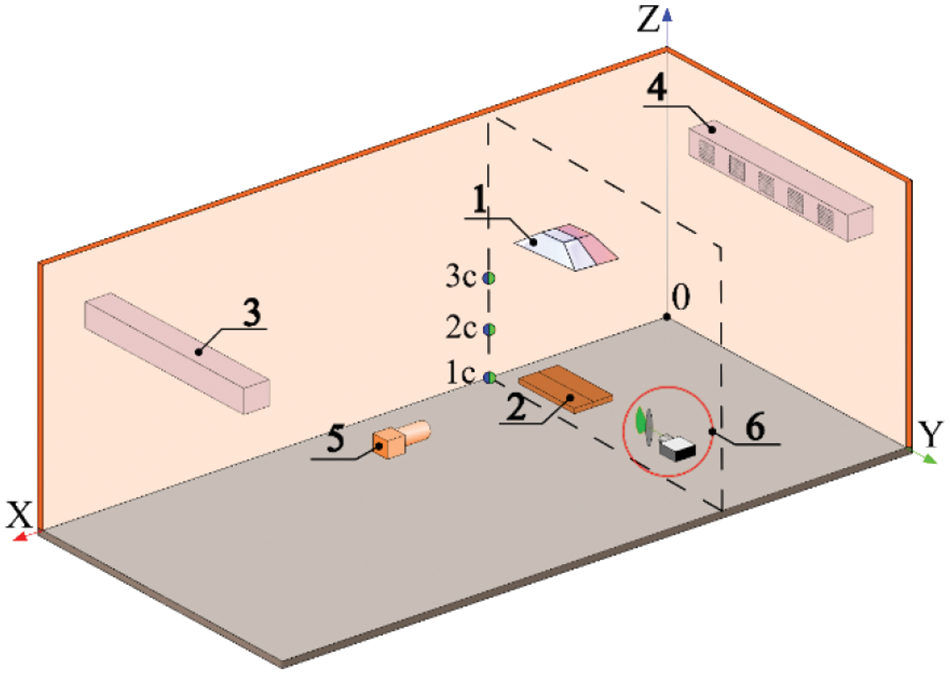
Figure 3: Scheme of the experimental room: 1—GIH, 2—horizontal panel (equipment model), 3, 4—air exchange system duct openings, 5—laser mirror system for converting the laser beam, 6—high-speed video camera, 1c, 2c, 3c—temperature and CO2 concentration sensors, respectively
The initial temperature during the studies was 7°C. The computer, shut-off and control equipment, and the gas cylinder were located outside the room under study to exclude their influence on the thermal regime in the temperature recording area. A supply and exhaust ventilation system with the following main characteristics was used: air flow rate of 420 m3/h, air velocity at the outlet of the supply duct was 2.3 m/s. The air inlet and outlet of the air exchange system were located at a height of 4 m. Air was taken from the street and heated to 7°C by a duct heater and then supplied to the room by a fan through the supply duct. Air was removed from the room through an exhaust duct with a fan. Air and solid surface temperatures were measured with thermocouples (12 pieces, made of 0.08 mm chromel-alumel wire with protection from thermal radiation, error 0.2°C). The CO2 concentrations in the study area were measured by non-dispersive infrared sensors with an error of 50 ppm. In order to ensure the possibility of estimating random measurement errors, all experiments under fixed conditions of their implementation were carried out at least three times. After that, the standard deviations and the corresponding variation coefficients were calculated. The values of the latter in all experiments did not exceed 4%.
Fig. 4 shows the main results obtained during experimental studies and mathematical modeling (Fig. 4b).
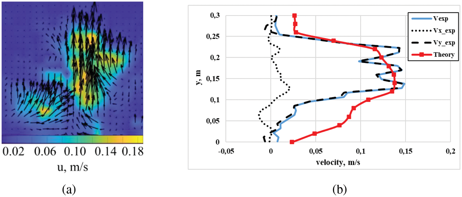
Figure 4: Air flow structure (a) and velocity profiles along the symmetry axis of the GIH influence zone (b) near the horizontal surface of the equipment after 60 min of heater operation
Experiments have shown that when the GIH is operating, the temperature of the panel surface and the air surrounding it increases, which leads to an increase in air speeds above it and the formation of an upward direction of the main air movement (Fig. 4).
Fig. 5 shows changes in air temperature and CO2 concentration on the symmetry axis of the GIH influence zone at a height of 0.79 m from the floor in the local working area, established experimentally and as a result of mathematical modeling.
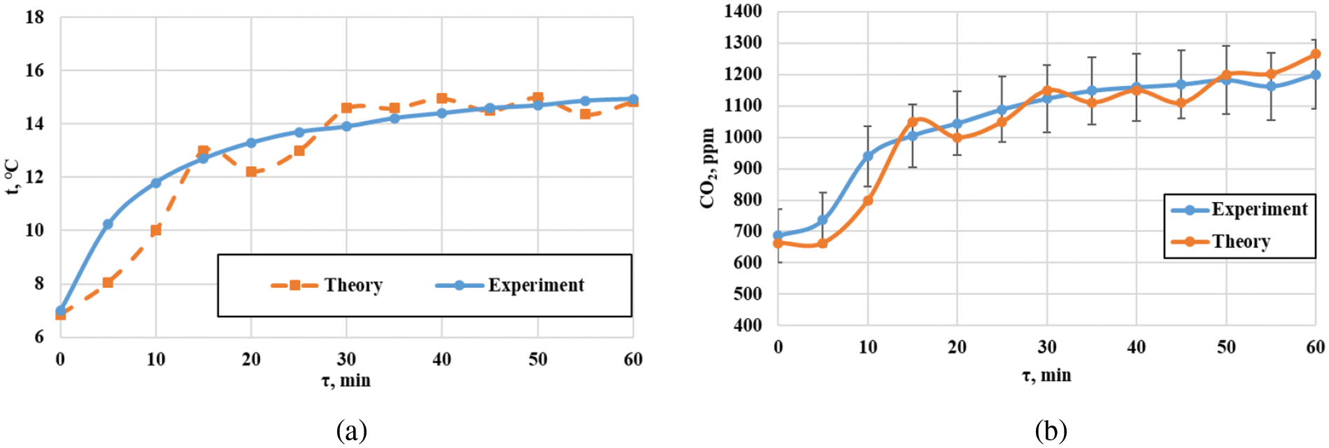
Figure 5: Change in air temperature (a) and CO2 concentration (b) over time at points z = 0.79 m (local operating zone) on the symmetry axis of the GIH influence zone after 60 min of GIH operation
As a comparative analysis of the results of physical and mathematical modeling shows, the difference between the measured and calculated values of temperatures and CO2 concentrations does not exceed 10% (Fig. 5), which allows us to recommend the created models for theoretical research and when selecting the parameters of ventilation devices for specific heating systems while observing the requirements of temperature comfort and fulfilling the standards for permissible air pollution with carbon dioxide in local working areas of premises.
3 Results of Numerical Modelling
The results of previously conducted experimental studies [8] show that within 40–60 min from the start of operation of the GIH and the air exchange system in the local working area, the values of air movement speeds and temperatures, as well as carbon dioxide concentrations, remain almost unchanged. The subsequent heating conditions can be designated as “quasi-stationary”. In this case the change in temperature and concentration fields occurs quite slowly. Moreover, the hydrodynamic picture of the flow remains practically unchanged. Only the values of the maximum and minimum velocities change insignificantly.
Fig. 6 shows the temperature (t) and CO2 concentration (χ) fields in the local working area for the option of locating the supply duct in the upper left part of the room and the exhaust duct in the lower right.
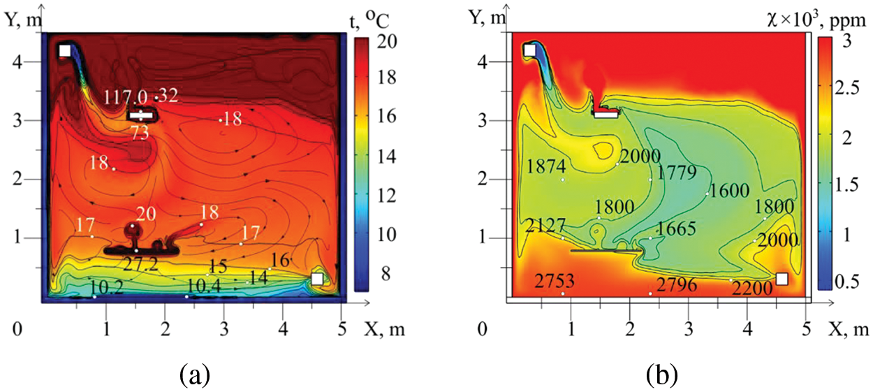
Figure 6: Temperature fields, streamlines (a) and CO2 concentration (b) formed after 60 min of GIH operation. Gvent = 0.01 kg/s; XVENT_L = 0.3 m; YVENT_L = 4.1 m; XVENT_R = 4.6 m; YVENT_R = 0.3 m
At a moderate air flow rate (Gvent = 0.01 kg/s), cold air from the air exchange system duct descends, carrying with it the heated GIH air and propane combustion products, the temperature of the mixture of which in the area of the equipment location increases to 18°C–20°C (Figs. 6a and 7a) compared to the mode without air exchange [23]. However, the CO2 concentration in this area increases (Fig. 7b), reaching values significantly higher than the regulatory one (1000 ppm) [7,8].
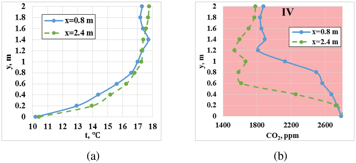
Figure 7: Changes in the main process characteristics t (a) and χ (b) on the left x = 0.8 m and on the right x = 2.4 m from the equipment model at a distance of 20 cm, formed after 60 min of operation of the GIH at a blown air flow rate of 0.01 kg/s
Such an arrangement of the air exchange system channels can be characterized with an increase in the air temperature in the local working area. It is typical due to the direction of air heated by influx from the GIH housing and natural gas combustion products into this area. At the same time, it is impossible to maintain the CO2 concentration value within the normal range (less than 1000 ppm). The creation of such areas is advisable only for heating the air and equipment in local areas without the presence of workers in them.
An analysis was carried out of another option for the location of the air inlet channel in the upper right part of the room (Fig. 8) and the outlet in the lower left one.
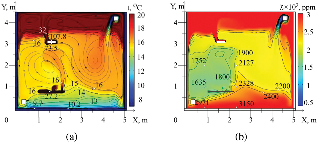
Figure 8: Temperature fields, streamlines (a) and CO2 concentration (b) formed after 60 min of GIH operation. Gvent = 0.01 kg/s; XVENT_L = 0.3 m; YVENT_L = 0.3 m; XVENT_R = 4.6 m; YVENT_R = 4.1 m
It has been established that, in this case, the temperatures and concentrations in the local working area also increase. Fresh air, mixing with heated GIH and CO2-polluted air, does not immediately enter the local working area, but moves along the right wall. A large vortex structure is formed in the right part of the room. The temperature distribution is uniform along the height of the local working area. The T values reach 18–20 degrees (Fig. 9a). The concentration of carbon dioxide is quite high mainly in the lower part of the local working area (Fig. 9b). This effect is due to the fact that heated and polluted air enters the lower part of this zone. The air in the upper part is heated due to heat exchange with the heated surface of the equipment. This air circulates in the left part of the room, capturing the local working area.
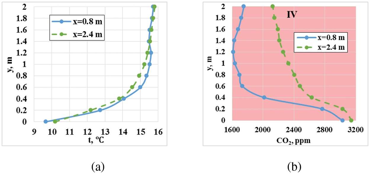
Figure 9: Changes in the main process characteristics t (a) and χ (b) on the left x = 0.8 m and on the right x = 2.4 m from the equipment model at a distance of 20 cm, formed after 60 min of operation of the GIH at a blown air flow rate of 0.01 kg/s
The analysis and generalization of the results of modeling the temperature fields and CO2 concentrations obtained for the two considered options for the position of the air exchange system channels provide grounds for considering another option: the inflow channel is shifted downwards to a height of 3 m (Fig. 10).
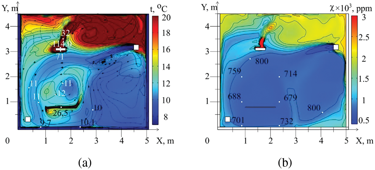
Figure 10: Temperature fields, streamlines (a) and CO2 concentration (b) formed after 60 min of GIH operation. Gvent = 0.04 kg/s; XVENT_L = 0.3 m; YVENT_L = 0.3 m; XVENT_R = 4.6 m; YVENT_R = 3.0 m
The calculation results show that cold fresh air at a flow rate of 0.04, mixing with heated air, enters the middle part of the room and flows around the left wall down to the outlet channel. In this case, three zones are formed: the upper circulation zone of heated and polluted air, the mixed air zone to the right of the panel and the zone of air heated from the panel surface near the local working area. In this zone, the air is heated to 14 degrees (Fig. 11a), and the CO2 concentration (Fig. 10b) does not exceed the standard (less than 800 ppm).
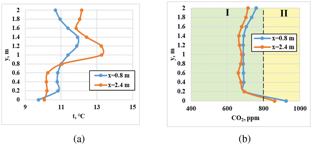
Figure 11: Changes in the main process characteristics t (a) and χ (b) on the left x = 0.8 m and on the right x = 2.4 m from the equipment model at a distance of 20 cm, formed after 60 min of operation of the GIH at a blown air flow rate of 0.04 kg/s
The distribution of temperatures and CO2 concentrations by the height of the local working area in this case is quite uniform (the difference in values is no more than 3°C) (Fig. 11). Based on the results of the numerical study, it can be concluded that such (Fig. 10b) arrangement of air supply and exhaust channels allows increasing the temperature level in the zone under consideration. This effect is achieved by directing air and combustion products of natural gas heated by thermal conductivity from the GIH housing into this zone, but the CO2 concentrations do not exceed the standard (less than 1000 ppm).
A theoretical analysis of the influence of the location of the fresh air inlet and outlet channels on the ambient temperature and the concentration of carbon dioxide in the local work zone under the conditions under consideration showed that the position of the air exchange system channels significantly affects the structure of flows and the formation of circulation zones, air temperature and CO2 concentration both in the local work zone and in the entire room. For example, the location of the air inlet areas at a height of 4.1 m and the outlet area at 0.3 m with a moderate flow rate (0.01 kg/s) leads to an increase in the temperature in the local working area by 60% (up to 20°C) compared to the mode without air exchange. At the same time, the CO2 concentration in this area increases, reaching values 2.5–3 times higher than the regulatory ones. This is due to the fact that the cold air from the ventilation system duct descends, entraining air heated by the GIH and propane combustion products. Increasing the fresh air flow rate to 0.02 kg/s leads to a decrease in the CO2 concentration in the local working area. However, the values are still higher than the regulatory ones. Further increase in air flow leads to the formation of a large-scale circulation vortex. The air flow coming from the supply channel passes along the periphery of the room along the enclosing structures. The temperature values in the local working area increase to 26°C and the CO2 concentrations are 3.5–4 times higher than the regulatory ones. It was found that with such an arrangement of the air exchange system input and output channel at air flow rates from 0.01 to 0.2 kg/s (double air exchange), it is impossible to reduce the CO2 concentration to the regulatory ones. The creation of such zones is advisable only for heating the air and equipment in local areas without the presence of a worker in them. Shifting the fresh air input area downwards by a height of 3 m leads to a decrease in the inflow of heated polluted air into the local working area. The air in this zone is heated to 14°C (30% higher than in the mode without air exchange), while the CO2 concentration does not exceed the permissible value (less than 1000 ppm).
The obtained results are quite non-obvious, if we do not consider the whole complex of simultaneously occurring thermophysical, hydrodynamic and diffusion processes occurring during operation of gas emitters and the air exchange system. The main reason for the obtained results is that when the intensity of air exchange and the position of the air inlet channels change, the intensities of all the main heat and mass transfer processes under consideration in the local working zone also change. For example, in the absence of air exchange or its weak intensity, the transfer of carbon dioxide occurs due to molecular diffusion and diffusion caused by natural convection. In this case, the carbon dioxide emitted by the emitter is involved in the circulation flows between the surface of the emitter and the equipment placed in the local working zone. If the intensity of fresh air inflow is sufficient to transform the vortex structures of natural convection, then the displacement of carbon dioxide from the local working zone occurs at a certain position of the air intake duct without involving the bulk of this gas coming from the GIH. At the same time, with high air flow rates and an irrational location of the intake duct, cold air captures most of the carbon dioxide and transports it downwards. It can be said that the complex configuration of the area in which the gas moves is also the cause of the results obtained. The results of the numerical modeling presented in the article show that only a change in the air flow rate while maintaining all other initial data unchanged leads to a change not only in the numerical values of all the main characteristics of the processes studied, but also in the configuration of the circulation flows. Based on the results of the research, it can be concluded that the considered technology for the formation of routine thermal modes while maintaining acceptable values of χ in a zone of certain dimensions is undoubtedly knowledge-intensive—without taking into account a large group of significant factors (processes of mixed convection, diffusion, radiation, intensity of the air exchange system, location of air supply and exhaust ducts, configuration of the local working area), the creation of systems for ensuring routine operating modes based on gas infrared emitters is impossible. It should also be noted that problems similar to those given in the article have not been considered previously due to the absence until recently of experimental results on determining the main characteristics of heat and mass transfer processes in the zone of influence of gas infrared emitters. In addition to the above, it should be noted that until recently the theory of mixed convection has not been developed intensively enough due to the specificity of such flows—the combined effect of viscous friction forces, pressure and temperature differences often leads to theoretical consequences that are unpredictable at the initial stage of analysis. The results obtained in the article illustrate the feasibility of solving problems of great practical importance within the framework of the mixed convection model.
The established regularities provide grounds for a number of conclusions on the practical application of thermal regime maintenance systems based on gas infrared emitters in practice.
1. The process of forming temperature fields and carbon dioxide concentrations in local working areas is multifactorial. The numerical values of temperatures and concentrations are affected not only by the emitter power and the influx of carbon dioxide from the surface of the latter. Significant factors are the flow rate of fresh air, its temperature, the coordinates of the position of the air inlet channel and its outlet from the production area, the coordinates of the position of the equipment (its position relative to the emitter and the air inlet and outlet channels). Therefore, varying all these significant factors in real ranges of change can provide the possibility of selecting the numerical values of each of the factors that ensure the scheduled thermal regime of the local workplace and the standard concentrations of carbon dioxide. The use of the developed model, algorithm and calculation method in wide ranges of change of the above-listed main significant factors provides the possibility of selecting numerical values of all operating parameters.
2. Replacing traditional convective heating systems with systems with gas infrared emitters provides the possibility of creating a scheduled thermal mode of local workplaces with heat costs 5–6 times less (depending on the size of the production facility) than when operating traditional convective heating systems.
3. When creating scheduled air quality modes in local work areas, energy costs for the operation of air exchange systems can be reduced by 4–5 times due to the lack of need for air exchange in large volumes of production facilities.
The results of the numerical modeling of heat transfer and diffusion processes under conditions of radiant heating of the local working area in the large premise showed the possibility of controlling the processes of formation of the thermal conditions of local working areas, when creating regulated (comfortable) conditions for CO2 concentration in the local working area. It is also possible to increase the energy efficiency of using open-type gas infrared heaters, varying the positions of the input and output channels of the air exchange system.
Acknowledgement: The authors would like to acknowledge the constructive remarks by worthy reviewers that led to this revised article.
Funding Statement: This work is supported by the Russian Science Foundation (grant number 20-19-00226).
Author Contributions: The authors confirm contribution to the paper as follows: study conception and design: Geniy Kuznetsov, Vyacheslav Maksimov; data collection: Felix Salikhov, Boris Borisov; analysis and interpretation of results: Vyacheslav Maksimov, Geniy Kuznetsov; draft manuscript preparation: Tatiana Nagornova. All authors reviewed the results and approved the final version of the manuscript.
Availability of Data and Materials: Data available on request due to restrictions of institution.
Ethics Approval: Not applicable.
Conflicts of Interest: The authors declare no conflicts of interest to report regarding the present study.
References
1. Kavga A, Karanastasi E, Konstas I, Panidis T. Performance of an infrared heating system in a production greenhouse. IFAC Proc. 2013;46(18):235–40. doi:10.3182/20130828-2-SF-3019.00017. [Google Scholar] [CrossRef]
2. Dudkiewicz E, Fidorów-Kaprawy N, Szałański P. Environmental benefits and energy savings from gas radiant heaters’ flue-gas heat recovery. Sustainability. 2022;14(13):8013. doi:10.3390/su14138013. [Google Scholar] [CrossRef]
3. Mikhailova LY, Kurilenko NI, Germanova TV, Shcherbakova EN. Decentralized heat supply systems for industrial buildings using natural gas from the Arctic zone. IOP Conf Series: Earth Environ Sci. 2022;990(1):012066. doi:10.1088/1755-1315/990/1/012066. [Google Scholar] [CrossRef]
4. Brown KJ, Farrelly R, O’Shaughnessy SM, Robinson AJ. Energy efficiency of electrical infrared heating elements. Appl Energy. 2016;162:581–8. doi:10.1016/j.apenergy.2015.10.064. [Google Scholar] [CrossRef]
5. Wang H, Kaur S, Elzouka M, Prasher R. A nano-photonic filter for near infrared radiative heater. Appl Therm Eng. 2019;153(9):221–4. doi:10.1016/j.applthermaleng.2019.03.001. [Google Scholar] [CrossRef]
6. Maznoy A, Kirdyashkin A, Pichugin N, Zambalov S, Petrov D. Development of a new infrared heater based on an annular cylindrical radiant burner for direct heating applications. Energy. 2020;204:117965. doi:10.1016/j.energy.2020.117965. [Google Scholar] [CrossRef]
7. GOST 30494-2011. Residential and public buildings. In: Microclimate parameters for indoor enclosures. Moscow, Russia: Standartinform; 2011. [Google Scholar]
8. EN 13779:2007. Ventilation for non-residential buildings. In: Performance requirements for ventilation and room-conditioning systems. Moscow, Russia: Standartinform; 2007. [Google Scholar]
9. Dudkiewicz E, Szałański P. Overview of exhaust gas heat recovery technologies for radiant heating systems in large halls. Therm Sci Engin Progress. 2020;18(4):100522. doi:10.1016/j.tsep.2020.100522. [Google Scholar] [CrossRef]
10. Farouk N, El-Rahman MA, Sharifpur M, Guo W. Assessment of CO2 emissions associated with HVAC system in buildings equipped with phase change materials. J Build Eng. 2022;51(10):104236. doi:10.1016/j.jobe.2022.104236. [Google Scholar] [CrossRef]
11. Majumdar D, Chatterjee S. Modelling accumulation of respiratory-CO2 in closed rooms leading to decision-making on room occupancy. MAPAN-J Metrol Soc India. 2020;35(3):323–32. doi:10.1007/s12647-020-00372-7. [Google Scholar] [CrossRef]
12. Bivolarova M, Snaselova T, Markov D, Melikov AK. CO2 based ventilation control—Importance of sensor positioning. In: Proceedings of the 15th ROOMVENT Virtual Conference, 2021 Feb 15–17; Torino, Italy. [Google Scholar]
13. Industrial heating systems by Schwank. Available from: https://schwank.co.uk/products/industrial-heating-systems/?lang=en. [Accessed 2024]. [Google Scholar]
14. Kurilenko NI, Kurilenko EY, Mamontov GY. New approach to microclimate parameter selection for the production area with heat supply systems based on gas infrared radiators. EPJ Web Conf. 2016;110:01033. doi:10.1051/epjconf/201611001033. [Google Scholar] [CrossRef]
15. Borisov BV, Vyatkin AV, Kuznetsov GV, Maksimov VI, Nagornova TA. Analysis of the influence of the gas infrared heater and equipment element relative positions on industrial premises thermal conditions. Energies. 2022;15(22):8749. doi:10.3390/en15228749. [Google Scholar] [CrossRef]
16. Borisov BV, Vyatkin AV, Kuznetsov GV, Maksimov VI, Nagornova TA. Numerical analysis of the influence of the air exchange system configuration on the temperature regime of local working areas in a room with a gas infrared heater. DOAJ. 2023;334(3):7–16. doi:10.18799/24131830/2023/3/3962. [Google Scholar] [CrossRef]
17. Azuma K, Kagi N, Yanagi U, Osawa H. Effects of low-level inhalation exposure to carbon dioxide in indoor environments: a short review on human health and psychomotor performance. Environ Int. 2018;121(151–6. doi:10.1016/j.envint.2018.08.059. [Google Scholar] [PubMed] [CrossRef]
18. Satish U, Mendell MJ, Shekhar K, Hotchi T, Sullivan D, Streufert S, et al. Is CO2 an indoor pollutant? Direct effects of low-to-moderate CO2 concentrations on human decision-making performance. Environ Health Perspect. 2012;120(12):1671–7. doi:10.1289/ehp.1104789. [Google Scholar] [PubMed] [CrossRef]
19. Allen JG, MacNaughton P, Satish U, Santanam S, Vallarino J, Spengler JD. Associations of cognitive function scores with carbon dioxide, ventilation, and volatile organic compound exposures in office workers: a controlled exposure study of green and conventional office environments. Environ Health Perspect. 2016;124(6):805–12. doi:10.1289/ehp.1510037. [Google Scholar] [PubMed] [CrossRef]
20. Kajtár L, Herczeg L. Influence of carbon-dioxide concentration on human well-being and intensity of mental work. Időjárás. 2012;116:145–69. [Google Scholar]
21. MacNaughton P, Spengler J, Vallarino J, Santanam S, Satish U, Allen J. Environmental perceptions and health before and after relocation to a green building. Build Environ. 2016;104(3):138–44. doi:10.1016/j.buildenv.2016.05.011. [Google Scholar] [PubMed] [CrossRef]
22. Norbäck D, Nordström K. Sick building syndrome in relation to air exchange rate, CO2, room temperature and relative air humidity in university computer classrooms: an experimental study. Int Arch Occup Environ Health. 2008;82(1):21–30. doi:10.1007/s00420-008-0301-9. [Google Scholar] [PubMed] [CrossRef]
23. Borisov BV, Kuznetsov GV, Maksimov VI, Salagaev TA, Salikhov SO, Salikhov FY. The influence of the air exchange system in combination with a gas infrared emitter on the thermal and diffusion regime in the local working area. In: Reports of the all-Russian conference with elements of a scientific school for young scientists. Novosibirsk, Russia; 2023 Aug 28–31 (In Russian). [Google Scholar]
24. Salikhov FY, Salagaev SO. Determination of the concentration of carbon dioxide in the zone of influence of a gas infrared emitter (In Russian). In: Collection of Articles of the III All-Russian Youth Conference with International Participation, 2023 Dec 12–14; Tomsk, Russia; p. 213–6. [Google Scholar]
25. Borisov BV, Vyatkin AV, Kuznetsov GV, Maksimov VI, Nagornova TA. Comparative analysis of two-dimensional and three-dimensional modeling of heat transfer during operation of a gas infrared heater indoor. DOAJ. 2024;335(3):61–9. doi:10.18799/24131830/2024/3/4506. [Google Scholar] [CrossRef]
26. Thermodynamics, heat transfer and fluid flow. In: DOE fundamentals handbook. Thermodynamics, heat transfer and fluid flow. Washington, DC, USA: U.S. Department of Energy; 2016. [Google Scholar]
27. Haynes WM. Handbook of chemistry and physics. 2015–2016. Boca Raton: CRC/Taylor & Francis; 2015. [Google Scholar]
28. Russell J, Cohn R. Comsol multiphysics. Scotland, UK: Lennex Corp; 2012. [Google Scholar]
29. ASHRAE 55-2017. Standard 55-2017–thermal environmental conditions for human occupancy (ANSI/ASHRAE approved). ASHRAE: Atlanta; 2017. [Google Scholar]
30. 1.2.3685-21. Hygienic standards and requirements for ensuring the safety and (or) harmlessness of environmental factors for humans. 2021 (In Russian). Available from: https://docs.cntd.ru/document/573500115?ysclid=m2ihc3dq1l154473404. [Google Scholar]
31. Siegel R, Howell J. Thermal radiation heat transfer. 4th ed. New York: Taylor & Francis; 2002. [Google Scholar]
32. Curtiss CF, Bird RB. Multicomponent diffusion. Ind Chem Res. 1999;38:2515–22. [Google Scholar]
33. Bird RB, Stewart WE, Lightfoot EN. Transport phenomena. 2nd ed. Hoboken: John Wiley & Sons, Inc.; 2007. [Google Scholar]
34. Bogatyrev AF, Makeenkova OA, Kucherenko MA. Transport properties of natural gas mixtures: viscosity, diffusion, thermal diffusion. JP J Heat Mass Transf. 2019;17(2):365–77. doi:10.17654/HM017020365. [Google Scholar] [CrossRef]
35. Marrero TR, Mason EA. Gaseous diffusion coefficients. J Phys Chem Ref Data. 1972;1(1):3–118. [Google Scholar]
Cite This Article
 Copyright © 2024 The Author(s). Published by Tech Science Press.
This work is licensed under a Creative Commons Attribution 4.0 International License , which permits unrestricted use, distribution, and reproduction in any medium, provided the original work is properly cited.


 Submit a Paper
 Propose a Special lssue
 View Full Text
 Download PDF
 Downloads
 Citation Tools