 Open Access
ARTICLE
Numerical Simulation of Heat Transfer Process and Heat Loss Analysis in Siemens CVD Reduction Furnaces
School of Mechanical Engineering, Southwest Petroleum University, Chengdu, 610500, China
* Corresponding Author: Kunrong Shen. Email:
Frontiers in Heat and Mass Transfer 2024, 22(5), 1361-1379. https://doi.org/10.32604/fhmt.2024.057372
Received 15 August 2024; Accepted 27 September 2024; Issue published 30 October 2024
Abstract
The modified Siemens method is the dominant process for the production of polysilicon, yet it is characterised by high energy consumption. Two models of laboratory-grade Siemens reduction furnace and 12 pairs of rods industrial-grade Siemens chemical vapor deposition (CVD) reduction furnace were established, and the effects of factors such as the diameter of silicon rods, the surface temperature of silicon rods, the air inlet velocity and temperature on the heat transfer process inside the reduction furnace were investigated by numerical simulation. The results show that the convective and radiant heat losses in the furnace increased with the diameter of the silicon rods. Furthermore, the radiant heat loss of the inner and outer rings of silicon rods was inconsistent for the industrial-grade reduction furnace. As the surface temperature of the silicon rods increases, the convective heat loss in the furnace increases, while the radiative heat loss remains relatively constant. When the inlet temperature and inlet velocity increase, the convective heat loss decreases, while the radiant heat loss remains relatively constant. Furthermore, the furnace wall surface emissivity increases, resulting in a significant increase in the amount of radiant heat loss in the furnace. In practice, this can be mitigated by polishing or adding coatings to reduce the furnace wall surface emissivity.Keywords
Nomenclature
| Specific heat capacity at constant pressure (J/(kg·K)) | |
| h | Convective heat transfer coefficient (W/(m2·K)) |
| Mm | Molar mass of gas mixture (kg/mol) |
| R | Generalized gas constant (8.314 J/(mol·K)) |
| Re | Reynolds number |
| T | Temperature (K) |
| ui | Velocity in different axial directions (m/s) |
| ρ | Gas density (g/m³) |
| λ | Thermal conductivity (W/(m·K)) |
| ε | Emissivity |
| μ | Kinetic viscosity (N·s/m2) |
| Ωu | Molecular collision integral (W/(m2·K)) |
Solar photovoltaic power generation has significantly matured as a key technology within the new energy industry framework. Silicon solar cells utilizing polysilicon as the principal material occupy a dominant position within the photovoltaic cell industry neighborhood [1]. The production of polysilicon encompasses a range of processes, including metallurgical methods [2], fluidized bed methods [3], silane pyrolysis methods [4], and modified Siemens methods [5]. The modified Siemens method accounts for 80% of global polysilicon production [6,7]. This method employs distilled and purified trichlorohydrosilicon (TCS) and H2 to prepare polysilicon by CVD in a reduction furnace [8], offering numerous advantages, including high-quality finished silicon material, a well-developed process, high safety, and mature processing technology of the preparation equipment [9]. However, it should be noted that the deposition process typically consumes around 90 kWh/kg of energy, accounting for over half of the overall energy used in polysilicon production. Furthermore, the energy cost of the modified Siemens method can account for up to 25% of the total cost of polysilicon production [10], with energy consumption representing a significant area of concern for scholars [11,12].
The modified Siemens method necessitates a high and stable deposition temperature to produce polysilicon. In practice, the process attains the requisite deposition temperature by energizing the inbuilt silicon rods and utilizing the Joule effect. In this process, the substantial temperature gradient between the silicon rods and the furnace wall leads to considerable energy dissipation during heat transfer in the reduction furnace. Consequently, the actual energy supplied to the chemical reaction process is relatively small, leading to high energy consumption. Scholars have based their research on the fundamental principles of fluid dynamics.
Del Coso et al. [13] conducted a numerical simulation of a polysilicon reactor with 36 pairs of silicon rods to investigate how different parameters, such as silicon rod diameters, rod arrangement, reactor inner wall temperature, and emissivity, affect radiative heat loss. By comparing the temperature distribution uniformity and production energy efficiency, they found that increasing the number of silicon rods, enhancing the reflectivity of the inner wall materials, and installing a heat shield can significantly reduce radiative heat loss. Ramos et al. [11] investigated the heat transfer process in a laboratory polysilicon reduction furnace using both experimental methods and numerical simulations, focusing specifically on radiative heat loss. Their findings indicate that reducing the inner wall emissivity from 0.80 to 0.70 decreases radiant heat loss by 3.8%, while a decrease from 0.50 to 0.30 results in a 25% reduction. When the emissivity was reduced from 0.80 to 0.70, the radiant heat loss was reduced by 3.8%. His team also investigated the effect of heat shielding on energy consumption in the Siemens reduction furnace [14]. Luo et al. [15] used a cold spray (CS) process to spray a highly reflective silver coating and a moderately hard nickel coating on the inner wall of the Siemens reactor to investigate the effect of the coatings on radiative heat loss. It was found that the silver coating could significantly increase the reflectivity of the inner wall surface and greatly reduce the radiative heat loss, and the wall bond strength was also increased from 3.7 to 35.4 MPa, which greatly improved the performance of the reduction furnace.
An et al. [16] conducted a numerical simulation of a developed 2D model with different channels and barrier settings to assess the local heat and mass transfer characteristics of a polysilicon CVD system. Experiments were conducted with varying speeds, temperatures, Nussel numbers, component concentrations, and other influencing factors for different channels. The results demonstrated that the configuration of barriers can enhance perturbation and result in enhanced local heat and mass transfer situation. Nie et al. [17] examined the Joule heating process in a Siemens reduction furnace featuring 48 pairs of silicon rods. They obtained key characteristics, including temperature, current density, and stress distribution across the rods in various rings. Notably, it was found that increasing the rod radius from 7 to 10 cm reduced the average energy consumption from 49 kWh/kg to about 38 kWh/kg. A new reactor with low energy consumption and controllable temperature of the gas phase was proposed based on a conventional polysilicon chemical vapor deposition (CVD) reactor [18]. The study examined the distribution of velocity, the temperature field, the concentration levels, and the energy consumption characteristics within the new reactor. The results demonstrate that the controllable gas-phase temperature in the new reactor effectively suppresses the generation of silica powder and reduces the contamination of the inner wall of the reactor by over 95%. The clean inner wall reduces the radiation, thereby reducing energy consumption. Previous studies have predominantly employed laboratory-grade or industrial-grade polysilicon reduction furnaces to investigate and elucidate the physical field distribution law within. There are, however, fewer studies that have endeavored to provide a comprehensive analysis of the two.
This paper presents a model of two types of polysilicon reduction furnaces: laboratory-grade and industrial-grade. The impact of various parameters, including the diameter of silicon rods, the surface temperature of silicon rods, the inlet gas flow rate, and the surface emissivity of the inner wall of the reduction furnace, on the heat transfer process in the polysilicon reduction furnace is investigated through numerical simulation. The findings from the numerical simulation were integrated to propose an effective strategy for enhancing energy efficiency and reducing consumption, offering theoretical support for the advancement of energy-saving technologies in the production process of the improved Siemens method.
A laboratory-grade Siemens polysilicon reduction furnace model was developed, as illustrated in Fig. 1, which contains a single silicon rod. The diameter of the silicon rod is 0.75 cm, the height of both the rod and the reactor is 53 cm, and the diameter of the reactor barrel is 15.5 cm.
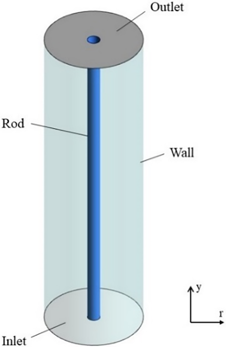
Figure 1: Physical model of a laboratory-scale reduction furnace
The model of the 12 pairs of rods industrial-grade Siemens reduction furnace is shown in Fig. 2a. The structural parts of the model include the bell, chassis, silicon rods, inlet and outlet tubes, and so on. The silicon rods in the reduction furnace are arranged in concentric rings, with a total of two rings. The inner ring has four pairs of silicon rods, while the outer ring has eight pairs of silicon rods. The silicon rods, measuring 2385 mm in length, are arranged in parallel, with each rod connected to its neighboring rods by a small curved body with a diameter of 230 mm. This chassis is depicted in Fig. 2b, which also illustrates the furnace’s joints for 24 silicon rods, 8 inlet nozzles, and 1 inlet outlet. The inlet nozzles are positioned between the two rings of silicon rods in a circular arrangement, while the outlet is located in the center of the base. The geometrical parameters of the reduction furnace are shown in Fig. 2 and Table 1.
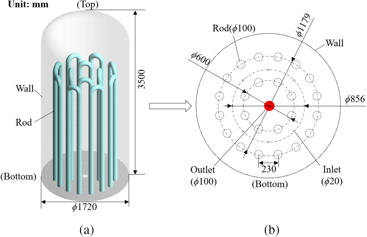
Figure 2: Physical modeling of the industrial-scale reduction furnace: (a) Physical model of industrial-scale reduction furnace, (b) Distribution of silicon rods in industrial-scale reduction furnace

The deposition process of polysilicon production in Siemens reduction furnaces encompasses intricate processes, including heat transfer and chemical reactions. This paper focuses on the direction of heat loss, so the physical model is simplified with the following assumptions:
(1) The reaction gas is a continuous medium.
(2) The reaction gas is treated as an incompressible ideal gas, and its state parameters are considered to be a function of temperature.
(3) The flow of the reaction gas in the furnace during the simulation is considered to be a constant flow, and the non-stationary term is ignored because the dimensionless time of silicon deposition is much larger than that of convection and component transport diffusion during the deposition process in the furnace.
(4) Given that the chemical reaction involved in silicon deposition has a minimal impact on the heat transfer process, the simulation does not consider the effect of the chemical reaction [14].
(5) It is assumed that the temperatures of both the silicon rods and the reaction furnace wall are constant, that the emissivity is treated as constant, and that both satisfy the gray body assumption.
In light of the aforementioned simplifying assumptions, the established control equations are as follows:
(1) mass equation:
where
where
(2) momentum equation:
For numerical simulations of industrial-scale polysilicon reduction furnaces, the standard k-ε model was chosen for the turbulence equations:
Turbulent kinetic energy k:
Turbulent kinetic energy dissipation rate ε:
where
(3) energy equation:
(4) radiation equation:
The DO radiation model [19] was chosen for the numerical simulation of radiation.
The inlet of the gas mixture is assigned a velocity boundary condition, the outlet is assigned a pressure outlet condition, and the gauge pressure is set at 0 MPa. The surface of the silicon rods and the inner wall of the reduction furnace are assigned a fixed temperature and no-slip boundary condition. The specific boundary conditions values for the laboratory-grade polysilicon reduction furnace and the industrial-grade polysilicon reduction furnace are shown in Tables 2 and 3, respectively.


2.4 Physical Parameters of Gas Mixtures
The specific heat capacity
where Xi corresponds to the mass fraction of substance of the ith gas in the gas mixture.
In this study, the gases were limited to TCS and hydrogen. The segmented functional equation was selected for the expression of specific heat capacity [20]. The specific heat capacity of a single gas is defined as:
where

2.5 Grid Delineation and Validation
The structured meshing of the physical mode of the laboratory-grade Siemens polysilicon reduction furnace is carried out in accordance with the procedure depicted in Fig. 3. Five sets of grid numbers, including 68,620, 79,772, 91,476, 103,840, and 111,848, were selected for the purpose of conducting an independence validation. The validation results are presented in Fig. 4. It can be demonstrated that when the number of grids reaches 79,772 or above, the convective heat transfer density remains essentially unchanged. In order to ensure the accuracy of the calculation and to conserve computational resources, 91,476 grids were subsequently selected for the calculation.
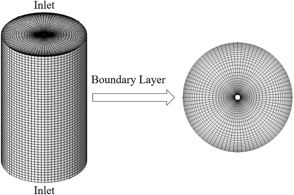
Figure 3: Schematic diagram of mesh delineation of a laboratory-grade reduction furnace
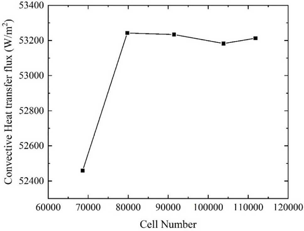
Figure 4: Laboratory grade reduction furnace grid assessment results chart
The Siemens industrial reduction furnace model with 12 pairs of silicon rods was discretized by polyhedral meshes and five mesh numbers were selected for mesh inertia-free validation: 2.87, 3.5, 4.5, 5.3, and 6.1 million. The results of the grid verification are presented in Fig. 5. It can be observed that the simulation results tend to stabilize when the number of grids is increased to 3.5 million. Consequently, the industrial-grade Siemens reduction furnace is selected for calculation with a grid number of 3.5 million.

Figure 5: Industrial reduction furnace grid irrelevance assessment results
2.6 Validation of Numerical Methods
To validate the accuracy of the adopted numerical method, a numerical simulation study of the laboratory-scale reduction furnace built by the team of Romas et al. [21] was carried out and the results were compared with the experimental data. The validation results are shown in Fig. 6. It can be observed that the numerical simulation results are largely consistent with the experimental results, with the maximum value of the simulation error being 2.4%. This indicates that the numerical method selected in this study is sufficient to meet the desired accuracy requirements.

Figure 6: Numerical validation results
3.1 Analysis of Numerical Results for Laboratory-Grade Siemens Reduction Furnaces
3.1.1 Effect of Silicon Rod Diameter
To explore how the diameter of silicon rods affects energy consumption in the reduction furnace, a series of numerical simulations were performed using various rod diameters. The flow in the reduction furnace is assumed to be laminar. Fig. 7 illustrates the calculated velocity field and temperature field distribution. The temperature distribution is shown on the left, and the velocity distribution is presented on the right. The figure shows that the temperature of the gas mixture gradually increases after entering the reaction furnace and being heated by the central silicon rod. Concurrently, the velocity boundary layer at the inlet is exceedingly thin due to the viscous effect, and the fluid convection heat transfer is pronounced. As the velocity boundary layer continues to develop, the thermal resistance near the wall gradually increases, and the convective heat transfer effect is weakened. It can be observed that the diameter of the silicon rods has a minimal impact on the distributions of temperature and velocity within the reduction furnace.

Figure 7: Temperature and velocity distributions for different silicon rod diameters: (a) 1 cm diameter, (b) 2 cm diameter, (c) 1 cm diameter
Fig. 8 illustrates the convective and radiant heat losses in the reduction furnace related to the diameter of the silicon rods. It is evident that increasing the rod diameter also increases the surface area available for heat exchange. This results in an increase in both convective and radiant heat exchange on the rod’s surface.

Figure 8: Effect of silicon rod diameter on heat loss: (a) Convective heat loss, (b) Radiant heat loss
3.1.2 Effect of Surface Temperature of Silicon Rods
As the surface temperature of the silicon rods increases, the temperature difference between the rods and the gas mixture and the furnace wall also increases. Figs. 9 and 10 illustrate the convective and radiative heat losses at different silicon rod surface temperatures. It can be observed that the quantity of convective heat loss gradually increases as the surface temperature of the silicon rods increases. The amount of convective heat loss increases from 249.44 to 295.483 W when the inlet temperature of the gas mixture is 373 K. It has been demonstrated that changing the inlet temperature is an effective solution to the phenomenon whereby the temperature difference between the gas flow and the surface of the silicon rods decreases as the inlet temperature is increased, and the convective heat loss decreases. As illustrated in Fig. 10, an increase in the surface temperature of the silicon rod from 1273 to 1473 K is accompanied by a corresponding exponential growth in radiant heat transfer, rising from 3187.37 to 5729.944 W. This is accompanied by a notable increase in radiant energy consumption.
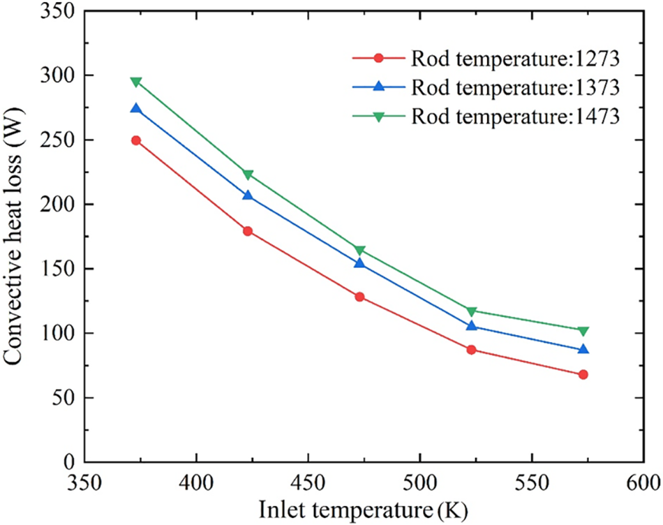
Figure 9: Effect of silicon rod surface temperature on convective heat loss

Figure 10: Effect of silicon rod surface temperature on radiant heat loss
3.1.3 Effect of Intake Air Temperature
The objective of this study is to investigate the impact of inlet gas temperature on convective heat loss. To this end, a series of simulation experiments were conducted to prove that with the increase in inlet gas temperature, gas radiation heat transfer changes are minimal. Consequently, the study of the inlet gas temperature is limited to its impact on convective heat loss. Fig. 11 illustrates the impact of inlet gas temperature on convective heat loss in the reduction furnace when the surface temperature of silicon rods is 1273 K of inlet gas. It can be observed that as the inlet gas temperature increases from 323 to 573 K, the convective heat exchange in the furnace decreases from 315.93 to 67.841 W. Consequently, it can be concluded that increasing the inlet temperature can result in a reduction in the energy consumption of the reduction furnace. Ideally, if a higher grade of heat energy is present in the exhaust gas, then the energy utilization can be improved by implementing a reheat cycle. However, it should be noted that increasing the inlet temperature affects the gas phase deposition rate and the quality of the deposited product and that increasing the inlet temperature itself requires additional energy consumption. Consequently, it can be expected that the general industrial production will control the inlet temperature in the range of 373 to 423 K. Therefore, when using this scheme to reduce the total energy consumption, it is necessary to ensure that the inlet temperature is controlled within this range.

Figure 11: Effect of inlet air temperature on convective heat loss
3.2 Analysis of Numerical Results for Industrial Siemens Reduction Furnaces
3.2.1 Effect of Silicon Rod Diameter
As the polysilicon material is continuously deposited and attached to the surface of the silicon rods during the deposition process, the diameter of the rods gradually increases. Consequently, the flow and heat transfer process in the furnace will be altered in accordance with this change in diameter. In this section, numerical experiments are conducted for five diameters of silicon rods to investigate the influence of rod diameter on convective and radiative heat transfer. The results are presented in Figs. 12 and 13.
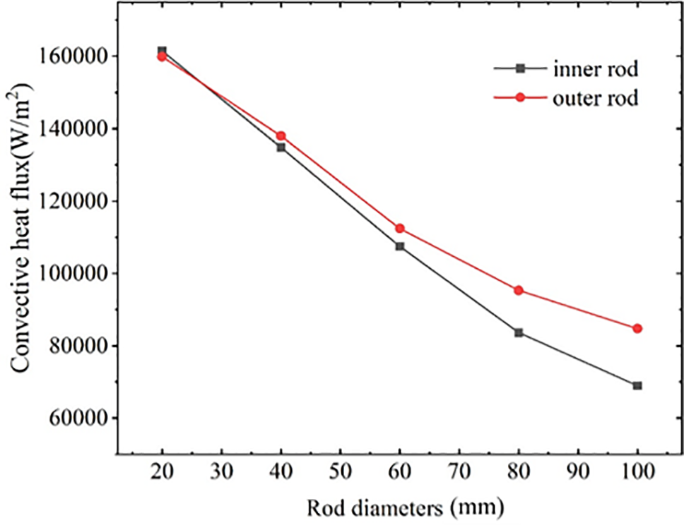
Figure 12: Effect of silicon rod diameter on convective heat fluxes
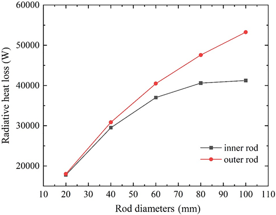
Figure 13: Radiation heat loss of different silicon rod diameters
As illustrated in Fig. 12, when the diameter of the silicon rods is 2 cm, the convective heat flux of the silicon rods arranged in the inner ring and the silicon rods arranged in the outer ring is 161,441 and 159,877 W/m2, respectively. Conversely, when the diameter of the silicon rods increases to 10 cm, the convective heat fluxes of the silicon rods arranged in the inner and outer rings are reduced to 68,972 and 84,725 W/m2, respectively. As the diameter of the silicon rods increases, the convective heat fluxes of both the inner and outer rings exhibit a declining trend. Furthermore, as the diameter of the silicon rods increases, the difference in convective heat transfer between the inner and outer rings also grows. This is evidenced by the fact that the convective heat fluxes on the surface of both the inner-ring and outer-ring silicon rods show a declining trend, with the difference between the two becoming increasingly pronounced. It is also observed that the convective heat loss of the outer-ring silicon rods accounts for the observed increase. It is noteworthy that, despite the tendency for convective heat flux to decrease with increasing rod diameter, the convective heat transfer capacity of a single rod tends to increase due to the increase in rod diameter and surface area. Consequently, convective heat loss in the furnace increases with increasing rod diameter.
As illustrated in Fig. 13, the radiant heat loss generally increases with an increase in the diameter of the silicon rods. However, the behavior exhibited by the outer and inner ring silicon rods is quite distinct. As the diameter of the silicon rods increases, the radiative heat loss from the outer ring rods rises more quickly, whereas the heat loss from the inner ring rods increases initially before stabilizing. This outcome is attributable to a multitude of factors. One such factor is the increase in silicon rod diameter, causing the outer layer of rods to block the inner layer. This arrangement decreases the radiation angle of the inner rods relative to the furnace wall surface, thereby reducing their radiant heat loss. Secondly, the manner in which the silicon rods are arranged will also have an impact. Different spacing between the inner and outer rings will result in a change to the rod’s angle of radiation, thus affecting the radiant heat loss. In general, a reasonable arrangement of the way to increase the diameter of the silicon rods can indeed reduce the radiation energy consumption while increasing the surface area of the silicon rods, which is more conducive to the deposition of polycrystalline silicon.
3.2.2 Effect of Surface Temperature of Silicon Rods
Fig. 14 illustrates the convective heat flux at different silicon rod surface temperatures. It can be demonstrated that when the diameter of the silicon rod and the inlet temperature are held constant, the surface temperature of the silicon rod increases from 1323 to 1523 K, accompanied by a nearly 70% increase in the convective heat flux on the surface of the silicon rod. As the surface temperature of the silicon rod increases, the heat flux on the surface of the silicon rod gradually increases. This is due to the increase in the surface temperature of the silicon rod, the temperature difference between the surface of the silicon rod and the mixture of gases gradually increases, coupled with the obvious vortex perturbation in the furnace, and the amount of convective heat transfer increases significantly. The temperature of the silicon rod surface can be effectively controlled to reduce convective heat loss. However, a surface temperature that is too low will result in a reduction in the deposition rate of silicon and an inferior quality of silicon, which is not suitable for polysilicon production.

Figure 14: Effect of silicon rod surface temperature on convective heat fluxes
The results of the effect of the surface temperature of silicon rods on radiant heat loss are presented in Fig. 15. It can be observed that the surface temperature of silicon rods increases from 1323 to 1523 K, while the radiant heat loss of single silicon rods in the inner ring increases from 34,323 to 60,441 W, and that of the outer ring increases from 45,293 to 79,759 W. The radiant heat loss in the furnace increases in direct proportion to the surface temperature of the rods. This phenomenon is observed to be consistent across both the inner-ringed and outer-ringed rods.

Figure 15: Effect of silicon rod surface temperature on radiant heat loss
It has been demonstrated that a moderate increase in the surface temperature of silicon rods can facilitate the surface deposition reaction and enhance productivity. However, an excessively high surface temperature may result in an enhanced gas-phase reaction advantage, leading to the deposition of silicon material in a powdery form that is less conducive to production safety. Consequently, the general industrial production of silicon rod surface temperature control at 1373 K or so ensures both production efficiency and furnace safety.
3.2.3 Effect of Intake Velocity
As illustrated in Fig. 16, the convective heat transfer heat flux on the surface of the silicon rods in the furnace increases with the increase of the inlet air velocity. As the inlet gas temperature is increased from 10 to 50 m/s, the convective heat flux on the surface of the inner-ring silicon rods increases from 68,972 to 82,087 W/m2, while that on the outer-ring silicon rods increases from 84,725 to 95,571 W/m2, exhibiting a comparable growth trend. This outcome is primarily attributable to the rise in inlet velocity, which intensifies the turbulent disturbance of the gas mixture within the furnace, thereby enhancing the forced convection effect.

Figure 16: Effect of intake velocity on convective heat fluxes
3.2.4 Influence of Emissivity of Reactor Walls
Fig. 17 illustrates the results of the effect of the emissivity of the inner wall surfaces on the radiative heat loss in the furnace of an industrial-scale reduction furnace having 12 pairs of 100 mm diameter silicon rods. It can be observed that the radiative heat loss on the surface of the inner and outer ring silicon rods increases significantly as the emissivity of the inner wall surface of the furnace increases. As the furnace wall emissivity increases from 0.1 to 0.9, the radiant heat loss on the surface of the inner ring single silicon rod increases from 13,046 to 53,519 W, while the outer ring single silicon rod increases from 16,943 to 71,025 W. The simulation results demonstrate that reducing the furnace wall emissivity has a positive effect on reducing energy consumption in the reduction furnace.

Figure 17: Effect of silicon rod surface temperature on convective heat fluxes
In general, to reduce radiant energy consumption in industrial production, special treatment of the inner wall surface is required. The inner wall of the shell is typically processed by profiling to reduce its emissivity to approximately 0.5. Furthermore, the use of silver, gold, and other lower-emissivity metal materials in the inner wall surface plating can be employed to minimize the inner wall surface emissivity and thereby reduce energy consumption and associated costs. However, the application of this additional treatment will result in increased costs. Therefore, it is essential to conduct a comprehensive analysis of the specific circumstances of the project in order to determine the most appropriate course of action.
In order to explore the effects of structural parameters and operating conditions on laboratory-grade and industrial-grade polycrystalline silicon reduction furnaces, a high-precision numerical model of chemical gas deposition of 12-pair rod polycrystalline silicon reduction furnaces was constructed based on the dynamic grid technology. The influences of structural parameters and operating conditions on the energy consumption of the polycrystalline silicon reduction furnaces were systematically investigated, and energy saving and consumption reduction schemes were innovatively proposed. It provides theoretical support for the development of energy saving and consumption reduction technology for improving the production process of Siemens method. The specific conclusions are as follows:
(1) The numerical model of the Siemens reduction furnace was established, and its algorithm was validated using experimental data from the Romas team. The comparison showed a relative error of only 2.4% between the numerical and experimental findings, confirming the reliability of the numerical method for investigating flow and heat transfer phenomena in polysilicon reduction furnaces.
(2) As the diameter of the silicon rods increases, both convective and radiative heat losses in the furnace also rise, primarily due to the larger surface area of the rods. Additionally, in the industrial-scale reduction furnace, the radiative heat loss from the inner and outer rings of silicon rods exhibits different behaviors. When the diameter of the rods increases from 2 to 10 cm, the convective heat flux in the inner ring decreases from 161,441 to 68,972 W/m², while in the outer ring, it decreases from 159,877 to 84,725 W/m².
(3) The convective heat flux on the surface of the silicon rods exhibited a notable increase of approximately 70% when the surface temperature of the rods was elevated from 1323 to 1523 K. The aforementioned temperature increase was applied to the surface of the silicon rods. Additionally, the radiative heat loss of single silicon rods situated within both the inner and outer rings demonstrated a considerable rise of 76.1%.
(4) With the increase of inlet temperature and inlet velocity, the convective heat loss decreases, and the radiant heat loss is unchanged.
(5) As the emissivity of the furnace wall increases from 0.1 to 0.9, the surface radiation heat loss of a single polysilicon rod located in the inner ring increases from 13,046 to 53,519 W, while the outer ring increases from 16,943 to 71,025 W. From the practical standpoint of the project, it is possible to reduce the emissivity of the furnace wall surface by polishing or layering. Concurrently, these processes will result in increased costs, necessitating a decision that is aligned with the actual requirements of the project and a reasonable cost control strategy.
Acknowledgement: Not applicable.
Funding Statement: This research was funded by the Natural Science Foundation Projects in Sichuan Province (No. 2022NSFSC0254).
Author Contributions: The authors confirm contribution to the paper as follows: Data curation: Kunrong Shen; Formal analysis: Kunrong Shen, Jin Wang; Funding acquisition: Kunrong Shen, Jin Wang; Investigation: Kunrong Shen, Wanchun Jin; Methodology: Kunrong Shen, Wanchun Jin; Software: Kunrong Shen, Wanchun Jin; Validation: Kunrong Shen; Visualization: Kunrong Shen, Wanchun Jin; Conceptualization: Jin Wang; Writing—original draft: Kunrong Shen. All authors reviewed the results and approved the final version of the manuscript.
Availability of Data and Materials: Data can be provided on request.
Ethics Approval: Not applicable.
Conflicts of Interest: The authors declare that they have no conflicts of interest to report regarding the present study.
References
1. Coletti G, Gordon I, Schubert MC, Warta W, Johannes Ovrelid E, Jouini A, et al. Challenges for photovoltaic silicon materials. Sol Energy Mater Sol Cells. 2014 Nov;130:629–33. doi:10.1016/j.solmat.2014.07.045. [Google Scholar] [CrossRef]
2. Méndez L, Forniés E, Garrain D, Vázquez AP, Souto A. Upgraded metallurgical grade silicon for solar electricity production: a comparative life cycle assessment. Sci Total Environ. 2021;789:147969. doi:10.1016/j.scitotenv.2021.147969 [Google Scholar] [PubMed] [CrossRef]
3. Gu G, Lv G, Ma W, Du S, Fu B. Numerical simulation of granular silicon growth and silicon fines formation process in polysilicon fluidized bed. Particuology. 2024;87(22):74–86. doi:10.1016/j.partic.2023.07.019. [Google Scholar] [CrossRef]
4. Li P, Hou R, Zhang C, Wang T. Hydrodynamic behaviors of a spouted fluidized bed with a conical distributor and auxiliary inlets for the production of polysilicon with wide-size-distribution particles. Chem Eng Sci. 2022 Jan;247(10):117069. doi:10.1016/j.ces.2021.117069. [Google Scholar] [CrossRef]
5. Wang Q, Jia B, Yu M, He M, Li X, Komarneni S. Numerical simulation of the flow and erosion behavior of exhaust gas and particles in polysilicon reduction furnace. Sci Rep. 2020 Feb 5;10(1):1909. doi:10.1038/s41598-020-58529-y [Google Scholar] [PubMed] [CrossRef]
6. Yadav S, Chattopadhyay K, Singh CV. Solar grade silicon production: a review of kinetic, thermodynamic and fluid dynamics based continuum scale modeling. Renew Sustain Energ Rev. 2017 Oct;78:1288–314. doi:10.1016/j.rser.2017.05.019. [Google Scholar] [CrossRef]
7. Zhao D, Peng Z, Xu Q, Li S, Yuan X, Ma W, et al. Energy saving of 42-pair Siemens reactor with different layouts for polysilicon production: three rings and four rings. Mater Today Commun. 2024 Aug;40:110202. doi:10.1016/j.mtcomm.2024.110202. [Google Scholar] [CrossRef]
8. Filtvedt WO, Holt A, Ramachandran PA, Melaaen MC. Chemical vapor deposition of silicon from silane: review of growth mechanisms and modeling/scaleup of fluidized bed reactors. Sol Energy Mater Sol Cells. 2012 Dec;107:188–200. doi:10.1016/j.solmat.2012.08.014. [Google Scholar] [CrossRef]
9. Bye G, Ceccaroli B. Solar grade silicon: technology status and industrial trends. Sol Energy Mater Sol Cells. 2014 Nov;130:634–46. doi:10.1016/j.solmat.2014.06.019. [Google Scholar] [CrossRef]
10. Li XG, Xiao WD. Silane pyrolysis to silicon rod in a bell-jar reactor at high temperature and pressure: modeling and simulation. Ind Eng Chem Res. 2016 May 4;55(17):4887–96. [Google Scholar]
11. Ramos A, Del Cañizo C, Valdehita J, Zamorano JC, Luque A. Radiation heat savings in polysilicon production: validation of results through a CVD laboratory prototype. J Cryst Growth. 2013 Jul; 374:5–10. doi:10.1016/j.jcrysgro.2013.03.043. [Google Scholar] [CrossRef]
12. Fotiadis DI, Boekholt M, Jensen KF, Richter W. Flow and heat transfer in CVD reactors: comparison of Raman temperature measurements and finite element model predictions. J Cryst Growth. 1990 Mar;100(3):577–99. doi:10.1016/0022-0248(90)90257-L. [Google Scholar] [CrossRef]
13. Del Coso G, Del Cañizo C, Luque A. Radiative energy loss in a polysilicon CVD reactor. Sol Energy Mater Sol Cells. 2011 Apr;95(4):1042–9. doi:10.1016/j.solmat.2010.10.001. [Google Scholar] [CrossRef]
14. Ramos A, Valdehita J, Zamorano JC, Cañizo CD. Thermal shields for heat loss reduction in siemens-type CVD reactors. ECS J Solid State Sci Technol. 2016;5(3):P172–8. [Google Scholar]
15. Luo XT, Li SP, Li GC, Xie YC, Zhang H, Huang RZ, et al. Cold spray (CS) deposition of a durable silver coating with high infrared reflectivity for radiation energy saving in the polysilicon CVD reactor. Surf Coat Technol. 2021 Mar;409:126841. doi:10.1016/j.surfcoat.2021.126841. [Google Scholar] [CrossRef]
16. An L, Zhang T, Lei X, Yang P, Liu Y. Local heat and mass transfer characteristics of different channel configurations in polysilicon chemical vapor deposition reactor. Sol Energy. 2020 Jan;196:494–504. doi:10.1016/j.solener.2019.12.059. [Google Scholar] [CrossRef]
17. Nie Z, Ramachandran PA, Hou Y. Optimization of effective parameters on Siemens reactor to achieve potential maximum deposition radius: an energy consumption analysis and numerical simulation. Int J Heat Mass Transf. 2018 Feb;117:1083–98. doi:10.1016/j.ijheatmasstransfer.2017.10.084. [Google Scholar] [CrossRef]
18. Huang Z, Liu C, Yuan X, Liu S, Liu F. Development of a polysilicon chemical vapor deposition reactor using the computational fluid dynamics method. ECS J Solid State Sci Technol. 2013;2(11):P457–64. doi:10.1149/2.027311jss]. [Google Scholar] [CrossRef]
19. Si W, Wang N, Zong Y, Dai G, Meng F, Yang Z, et al. A revisit from CVD kinetics to CVD reactor: investigating uniform growth mechanism of polysilicon in a reduction furnace. Chem Eng Sci. 2024 Aug;295:120162. doi:10.1016/j.ces.2024.120162. [Google Scholar] [CrossRef]
20. Yaws Carl L. Matheson gas data book. New York: McGraw-Hill Professional; 1971. [Google Scholar]
21. Ramos A, Rodríguez A, Del Cañizo C, Valdehita J, Zamorano JC, Luque A. Heat losses in a CVD reactor for polysilicon production: comprehensive model and experimental validation. J Cryst Growth. 2014 Sep;402:138–46. [Google Scholar]
Cite This Article
 Copyright © 2024 The Author(s). Published by Tech Science Press.
This work is licensed under a Creative Commons Attribution 4.0 International License , which permits unrestricted use, distribution, and reproduction in any medium, provided the original work is properly cited.


 Submit a Paper
 Propose a Special lssue
 View Full Text
 Download PDF
 Downloads
 Citation Tools