 Open Access
ARTICLE
Influence of the Channel Design on the Heat Exchange Characteristics of Pulsating Flows in the Supply System of an Engine
Turbines and Engines Department, Ural Federal University named after the first President of Russia B. N. Yeltsin, Yekaterinburg, 620062, Russia
* Corresponding Author: Leonid Plotnikov. Email:
(This article belongs to the Special Issue: Heat and Mass Transfer in Energy Equipment)
Frontiers in Heat and Mass Transfer 2024, 22(5), 1309-1322. https://doi.org/10.32604/fhmt.2024.056680
Received 28 July 2024; Accepted 23 September 2024; Issue published 30 October 2024
Abstract
Heat engines based on reciprocating machines remain in demand as energy converters in a variety of industries around the world. The aim of the study was to evaluate the gas-dynamic, consumable and heat exchange characteristics of non-stationary air flows in a supply system with transverse profiling of valve channels based on experimental studies. Valve channels with cross sections in the form of a circle, square and triangle were used to control the consumable and heat exchange characteristics of the flows in the supply system of the reciprocating-engine model. The article presents data on changes in local velocity, volumetric airflow and instantaneous heat transfer coefficient of non-stationary airflow in supply systems with different valve channel designs. A spectral analysis of the pulsations of the local heat transfer coefficient was also performed. The Nusselt number was calculated for the studied supply systems. The figured valve channels lead to an increase in the volumetric airflow through the supply system up to 32% compared with the basic configuration. The use of a square valve channel leads to suppression of heat transfer (drop is about 15 %) compared to the basic supply system, and the use of a triangular valve channel causes an intensification of heat transfer (growth is about 17.5%). The obtained data can be useful for refining mathematical models, adjusting machine learning algorithms, and improving design methods for supply systems of reciprocating machines to improve their technical, economic, and environmental characteristics.Keywords
Heat engines based on reciprocating-machines remain in demand as energy converters in a variety of industries around the world [1]. It is known that the quality of gas exchange processes (filling and emptying of the cylinder through poppet valves) significantly determines the environmental, technical and economic indicators of the reciprocating internal combustion engine (ICE) [2,3]. Moreover, these processes are periodic (a reciprocating-engine is a cyclic machine), fast-flowing (the period is up to 100 Hz) and complex (spatial flow with the influence of heat exchange and taking into account moving parts). Therefore, it is necessary to further study and improve the physical phenomena in the supply (inlet) and discharge (outlet) systems to improve the operational and environmental performance of ICEs. This study is aimed at studying the influence of the cross–sectional shape (CSS) of the valve channel on the gas dynamics and heat transfer of pulsating flows in the supply system of a reciprocating-engine model.
The geometry (construction) of the parts of the supply system significantly affect the technical and economic indicators of the ICE, therefore scientists and engineers pay a lot of attention to optimizing the design of the inlet manifold and valve channel [4–7]. So, Silva et al. [4] proposed and studied the design of an inlet manifold with variable length depending on the engine operating mode. The length of the manifold affects the filling of the cylinder, as well as torque, power and specific fuel consumption. Jiang et al. [5] developed an optimizer to determine the best ratio of the length and diameter of the inlet manifold for a gasoline reciprocating-ICE. They formulated specific recommendations for choosing the geometric dimensions of the collector. The simulation results were successfully confirmed through engine bench tests. Song et al. [6] presented results on optimizing the configuration (geometric dimensions) of the valve channel of the cylinder head based on numerical modeling and machine learning algorithms. The calculation results were verified through laboratory studies in stationary modes of purging the ICE supply system. The developed methods can be used for upgrading existing thermal engines and for creating advanced models of power machines for various purposes.
Another popular and effective area of research is to develop methods for creating large vortices in an engine cylinder through the use of shaped valve channels in the form of spirals and/or screws [8–12]. For example, Wang et al. [8] studied the creation of a controlled vortex during the inlet process and its effect on cylinder filling and reciprocating-ICE power. An increase in the vortex number by three times causes an increase in power up to 5.79%. Ichiyanagi et al. [9] studied the effect of a spiral valve channel on the stream pattern in a cylinder using experimental methods (particle image velocimetry (PIV) system). The vortex size from the spiral channel has a significant impact on the flow structure, the processes of mixture formation and combustion, as well as the operational performance of the ICE. Zhao et al. [10] described detailed results on the effect of inlet flow swirl on the processes of mixture formation and combustion in a gasoline engine. Controlled vortex formation can cause an increase in the efficiency of the reciprocating-ICE within 3.5%. Also, Ichiyanagi et al. [11] studied the inlet tangential and helical valve channels in the cylinder head for the combustion process in engines operating on complex (hard-to-burn) fuels. Turbulization of the flow and the creation of large vortices improve the mixing of fuel and air, increase the combustion rate and intensify mass transfer. Controlled intake and cylinder flows are an effective way to improve the performance of reciprocating-engines.
There are also scientific and technical works on the creation of original and highly efficient supply systems for reciprocating-ICEs [13–16]. Ikhtiar et al. [13] installed a plate heat exchanger in the engine supply system to cool the inlet air in order to improve the environmental performance of the ICE. The use of a heat exchanger made it possible to reduce CO emissions by 43.6% and NOx by 64.5%. Siqueira Mazzaro et al. [14] used Herschel-Quincke tubes in a supply system to reduce the amplitudes of flow pressure pulsations during the filling of the cylinder. This technical solution can significantly increase the specific engine power. Xie et al. [15] proposed a systematic approach based on modern computer technologies for deep modernization of the design of the ICE supply system. The new supply system had increased productivity compared to the basic design.
The development of digital systems, computing power and mathematical apparatus has led to the active development of physical and mathematical models (PMM) for a detailed study of gas dynamics and heat transfer during the inlet process for various aspects [17–20]. Li et al. [17] developed an original PMM to study the stream pattern in the supply system. The applied function of this model was to estimate the hydraulic resistance of supply systems of various designs. For example, the authors reduced hydraulic resistance by 22% by upgrading the configuration of parts and assemblies. Yang et al. [18] proposed a PMM for assessing the level of unevenness of three-dimensional air flow in the supply pipeline. Bondar et al. [19] created a complex PMM of the supply system considering additional processes: fuel and water injection into the inlet manifold. Such PMMs are necessary for a detailed study of physical processes and accurate prediction of the technical characteristics of systems and the reciprocating-engine. The creation of digital twins of the engine’s supply and outlet systems and the engine is a major task for engineers and scientists.
Moreover, PMMs are also widely and actively used to create control systems for reciprocating-ICEs in real time [21–24]. Kumar et al. [21] created a PMM for mutual prediction of the processes of filling and emptying the cylinder. This model contributed to the creation of a more accurate, faster and more efficient ICE control system. Lujan et al. [22] developed a digital model for determining air flow through the supply system and supplemented it with neural network algorithms to control engine operation. Pulpeiro González et al. [23] proposed a similar digital model based on neural networks for the supply system and turbocharger. The application of machine learning algorithms and neural networks makes it possible to improve engine performance in transient conditions and significantly improve economic and environmental performance.
Also, scientists and specialists solve narrow applied problems through research and improvement of gas dynamics and heat exchange in the supply system: matching the characteristics of the flow in the cylinder and fuel spray by a nozzle to improve the environment [25], monitoring the technical condition of the reciprocating-ICE using data on gas flow through the supply and discharge systems [26], assessment of engine reliability and efficiency at high air pressure in the supply manifold [27], reduction of gas-dynamic noise in the inlet and outlet processes [28].
Thus, the purpose of this work was to evaluate the gas-dynamic and heat transfer characteristics of pulsating air flows in a supply system with valve channels having different CSSs based on laboratory research methods.
2 Experimental Setups, Measuring Instruments, Experimental Methods
The gas dynamics and heat exchange of pulsating flows in the supply system were studied on a model of a reciprocating-engine with a crankshaft driven by an electric motor in the absence of combustion in the cylinder (Fig. 1). Heat flows from the fuel combustion process were not taken into account in the study. One cylinder was used during the experiments. The other cylinder was missing a piston group and parts of the gas distribution mechanism. The crankshaft rotation speed n was controlled in the range from 600 to 3000 min−1 using a frequency converter. The pulsating mode of air flow was created due to the reciprocating movement of the piston (vacuum in the cylinder) and the cyclic operation of the valves. The valve opening and closing times were determined by the prototype engine and remained constant in all modes.
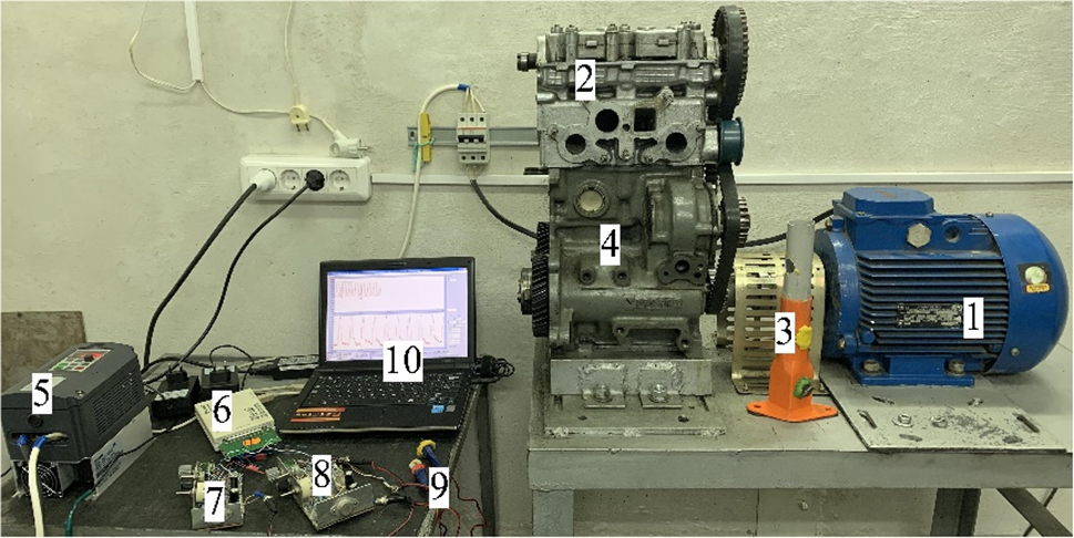
Figure 1: Photo of the laboratory bench: 1–electric motor; 2–cylinder head with a square valve channel; 3–supply pipe (disconnected from the cylinder head); 4–cylinder block with a piston group and a crank mechanism; 5–frequency converter; 6–analog-to-digital converter; 7–constant temperature HWA (wx); 8–constant temperature HWA (αx); 9–sensors for constant temperature HWA (wx and αx); 10–laptop
The gas-dynamic system consisted of a supply (straight) pipe, a valve (curvilinear) channel, an inlet valve and a cavity (cylinder) of variable volume (Fig. 2a). The supply system was as similar as possible to that of the prototype engine.
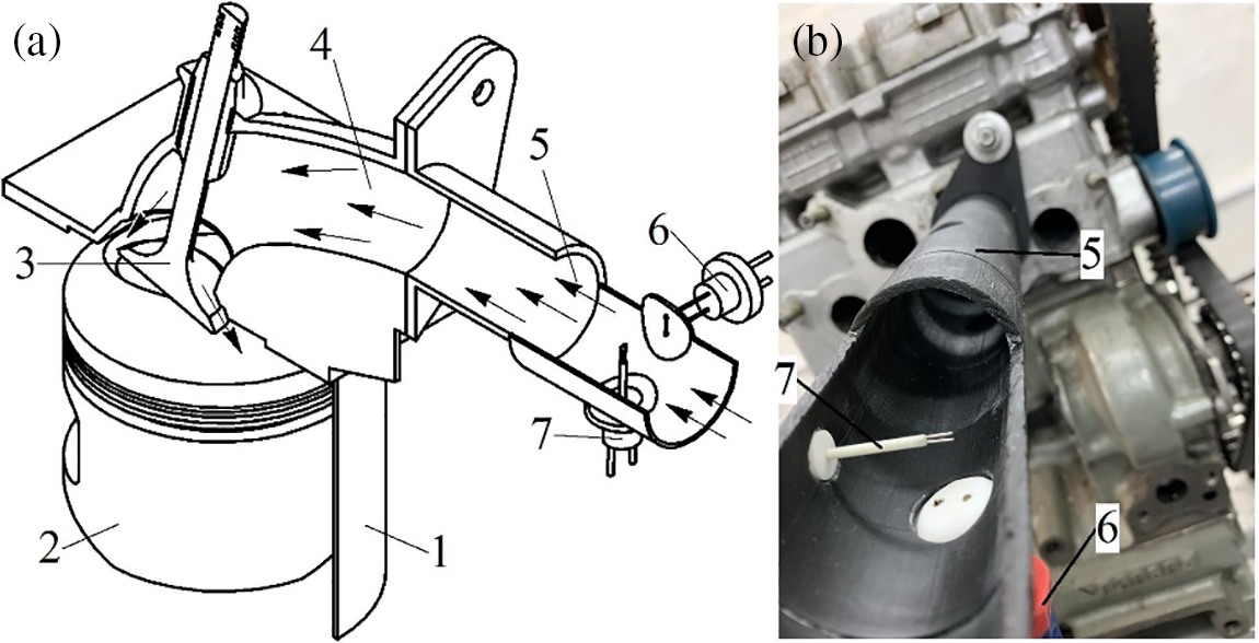
Figure 2: General view of the supply system (a) and photograph of constant temperature HWA sensors in the pipeline (b): 1–cylinder; 2–piston; 3–valve; 4–valve channel; 5–supply pipeline; 6–constant temperature HWA sensor (αx); 7–constant temperature HWA sensor (wx)
Valve channels with cross sections in the shape of a circle (basic version), square and triangle were used to regulate the gas-dynamic and heat transfer characteristics of the flows in the engine supply system (Fig. 3). The internal diameter of the round (base) channel was 32 mm, the side of the square was 32 mm, and the side of the triangular was 54 mm. The geometry of the channels was chosen based on the equality of equivalent hydraulic radii for all CSSs. This approach was applied to keep the hydraulic resistance unchanged for all figured valve channels.
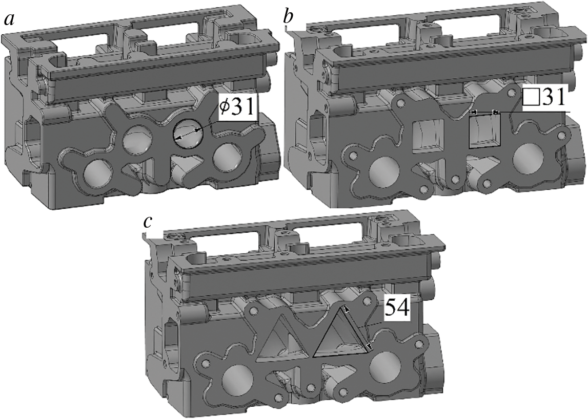
Figure 3: Three-dimensional models of cylinder heads with valve channels having different cross–sectional shapes: a–circle (●); b–square (■); c–triangle (▲)
It is known that longitudinal vortex structures arise in pipes with transverse profiling, which have a noticeable effect on gas dynamics and heat transfer of flows in various applications [29,30].
Cylinder heads with shaped valve channels were made by casting from aluminum alloy. The internal surfaces of the shaped channels were slightly processed mechanically until an acceptable roughness and cross-sectional shape were achieved. Cylinder heads with figured valve channels had standard elements, mounting dimensions and basic valve timing in accordance with the basic engine configuration.
The instantaneous values of the local velocity wx and the local heat transfer coefficient (HTC) αx of the pulsating air flow in the supply pipe were measured during the experiments. The thermal anemometry method based on a constant temperature hot-wire anemometer (HWA) and two types of thermal sensors with a filament sensing element was used to determine wx and αx [31,32]. A possible design of the HWA sensors is shown in Fig. 4. A photograph of installing thermal sensors in the supply pipeline is shown in Fig. 2b. The control section with thermal sensors was located at a distance of 100 mm from the inlet port in the cylinder head.
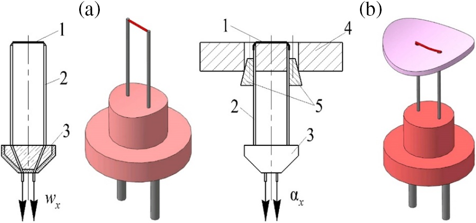
Figure 4: Designs of HWA sensors for determining instantaneous values of flow velocity wx (a) and local heat transfer coefficient αx (b): 1–sensitive element (5 mm long, 5 μm diameter thread); 2–holder; 3–sensor base; 4–fluoroplastic substrate; 5–wedges for fixing the substrate
The correct functioning of the HWA with sensors and the reliability of the measured values were checked according to known patterns: the dependence between the current strength i2 and the velocity w0.5 should be linear [33,34]. Accordingly, this linear dependence was successfully confirmed by experiments for the considered measuring system based on an HWA with sensors (Fig. 5). The resulting function i2 = f (w0.5) is linear with a standard deviation of less than 0.5%.
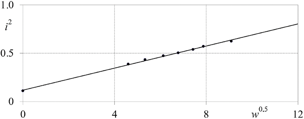
Figure 5: Linear dependence of i2 on w0.5 for for the measuring system based on the HWA with sensors (i–electric current strength, A; w–air flow speed, m/s)
The pressure (differential pressure sensors (Russia)) and temperature (via a copper-constantan thermocouple) of the flow, as well as the shaft speed (via a tachometer) and the position of the piston (also via a tachometer) in the cylinder were also measured in this study. The air temperature in the supply system was 22–24°C. The experiments were carried out at standard atmospheric pressure of 98.2 kPa. The air flow rate V through the supply system was calculated by integrating the flow velocity vs. time over the period from the moment the valve opened to its closure.
Experimental data from analog measuring instruments were digitized using an analog-to-digital converter (ADC) for further processing in a specialized program and visualization. A proven ADC from L-Card (Russia) was used. Experimental data were processed in the LGraph2 program (Russia). The method of collecting and processing experimental data was as follows: (1) analog signals from sensors were sent to the ADC L-Card; (2) data in the form of a digital code were sent to the program LGraph2 from the ADC; (3) the program LGraph2 processed and visualized experimental data.
The relative uncertainty for wx was 5.5%; the relative uncertainty for αx was 10.8%; the relative uncertainty for n was 0.5%; the relative uncertainty for the air flow rate V was 6.1%; the relative uncertainty for determining temperature was 1.5%; the relative uncertainty for determining atmospheric pressure was 1.0%.
3 Unsteady Thermophysical Processes in the Supply System of a Reciprocating-Engine Model
The change in local speed wx and instantaneous HTC αx in time τ for a full cycle (2 shaft revolutions) of a four-stroke engine is shown in Figs. 6 and 7 for different crankshaft rotation speeds n.
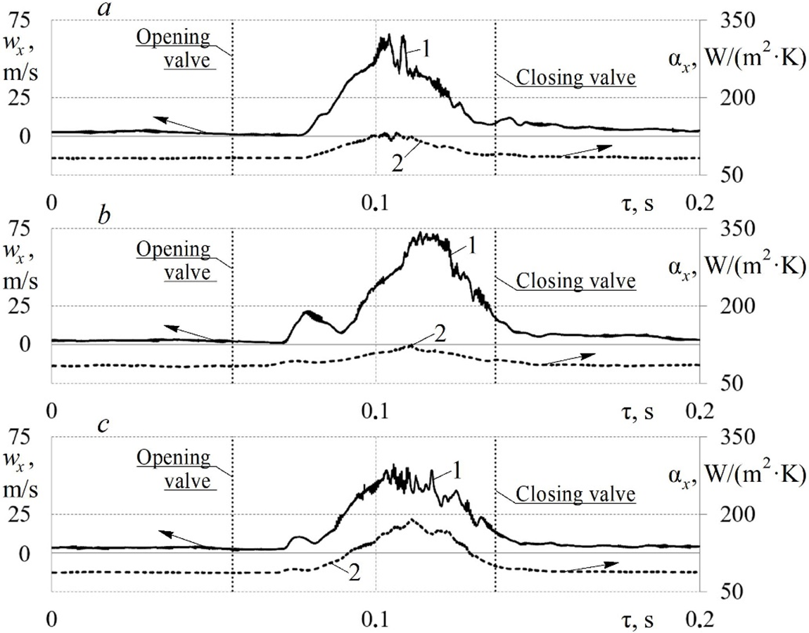
Figure 6: Changes in the local velocity wx (1) and the local HTC αx (2) of pulsating air flows in time τ at n = 600 min−1 in supply systems with valve channels having different cross–sectional shapes: a–(●); b–(■); c–(▲)
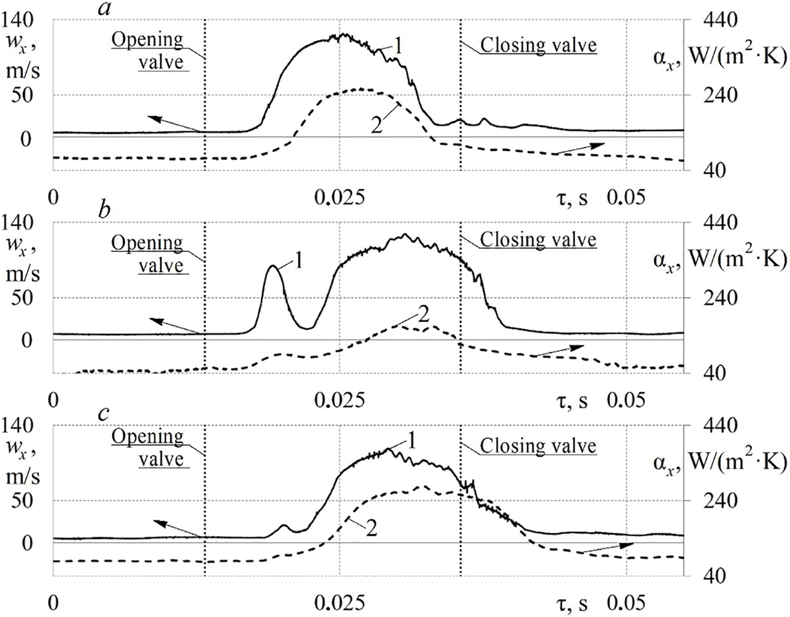
Figure 7: Changes in the local velocity wx (1) and the local HTC αx (2) of pulsating air flows in time τ at n = 2100 min−1 in supply systems with valve channels having different cross–sectional shapes: a–(●); b–(■); c–(▲)
The CSS of the valve channel has a noticeable effect on the gas dynamics and heat exchange of flows in the supply system at low n (Fig. 6). The active growth of the wx = f(τ) begins a certain period after the valve opens, which is explained by the creation of the necessary vacuum in the cylinder to begin air movement in the supply system. There is one peak with significant velocity fluctuations around the maximum local velocity for the basic (circular) valve channel configuration (Fig. 6a). The application of a square valve channel results in an earlier onset of active growth of the wx = f(τ) (Fig. 6b). There are also two peaks in the wx = f(τ). In this case, the magnitude of the pulsation amplitudes wx becomes noticeably smaller. There is a low increase in maximum flow velocity of up to 6% when using a square valve channel compared to a base round channel. The application of a triangular valve channel, on the contrary, results in a decrease in the maximum values of wx within 7% (Fig. 6c). This can be explained by a substantial increase in the cross–sectional area of the triangular channel (by approximately 30% compared to the circle). There are also two peaks of the wx = f(τ) for a triangular valve channel.
The αx = f(τ) repeats the function wx = f(τ) and is smoother (Fig. 6). The application of a triangular valve channel causes a significant increase in the maximum values of αx within the range of up to 45% compared with the basic design of the cylinder head (Fig. 6). In this case, the application of a square channel, on the contrary, leads to a slight decrease in the maximum αx in comparison with the base. The values of αx are in the range from 65 to 200 W/(m2·K) for all studied cross sections of the valve channel for n = 600 min−1.
A change in the n also leads to a substantial transformation of the gas dynamics and heat transfer of pulsating flows in the supply system with different valve channels (Fig. 7). An increase in n from 600 to 2100 min−1 results in the maximum values of wx to rise almost twice (from 70 to 140 m/s). The application of figured valve channels also causes the formation of two peaks in the wx = f(τ). Also, velocity fluctuations in the region of maximum wx values are significantly reduced for all valve channel designs.
The maximum values of αx increased from almost 105 to 248 W/(m2·K) with an increase in shaft rotation speed from 600 to 2100 min−1 for the basic design of the valve channel in the cylinder head (Fig. 7a). A similar pattern remains for figured valve channels: there is an increase in the maximum values of αx by more than 2 times.
Experimental data on instantaneous gas dynamics and heat transfer can be useful for refining PMMs of processes in the supply and outlet systems of ICEs, as well as for creating and tuning machine learning algorithms [35].
The application of a valve channel in the shape of a square and a triangle leads to a substantial improvement in flow characteristics through the supply system of the reciprocating-ICE model (Fig. 8).

Figure 8: Histograms of volumetric air flow V from the crankshaft rotation frequency n in supply systems with valve channels having different cross–sectional shapes: 1–(●); 2–(■); 3–(▲)
The increase in volumetric flow V through a supply system with a square valve channel is about 30% for 600 > n > 1600 min−1; increase in V is about 20% for 1700 > n > 2100 min−1; and the increase in V is about 10% for n > 2200 min−1. A similar trend occurs for the triangular valve channel: the increase in V is about 32% for 600 > n > 1600 min−1; increase in V is about 21% for 1700 > n > 2100 min−1; and the increase in V is about 17% for n > 2200 min−1. It should be noted that similar positive effects were observed when using shaped inlet pipes in the engine supply system [36].
Additionally, the volumetric efficiency VE was calculated for different shaft speeds of the studied engine model (Fig. 9). The application of figured valve channels results in an increase in VE up to 30% for 600 < n < 2100 min−1 in comparison with the basic design of the supply system. The increase in VE in the case of using figured channels for n > 2500 was 8–18%. Moreover, the variation coefficient for V and VE did not exceed 5.5% during the experiments in the entire range of rotation frequencies n. There is potential for further increase in volumetric efficiency for the engine configuration under consideration through supply system modifications.
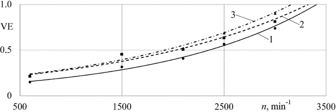
Figure 9: Dependences of volumetric efficiency VE on crankshaft speed n in supply systems with valve channels having different cross–sectional shapes: 1–(●); 2–(■); 3–(▲)
Confirmation of the improvement of the flow characteristics of the supply systems with figured channels through tests on an operating engine is the next stage of research in the future.
A significant change in gas-dynamic conditions in the supply system of a reciprocating-ICE should have a noticeable impact on the level of heat transfer. Therefore, the dependences of the Nusselt number Nu on the Reynolds number Re of pulsating flows in the supply system for the base and figured valve channels were obtained (Fig. 10). The patterns turned out to be multidirectional.
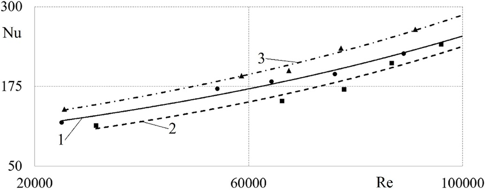
Figure 10: Dependences of the Nusselt number Nu on the Reynolds number Re of pulsating flows in supply systems with valve channels having different cross–sectional shapes: 1–(●); 2–(■); 3–(▲)
The application of a triangular valve channel leads to an increase in Nusselt number Nu by 10–17.5% compared to the basic supply system. Whereas, the use of a square valve channel, on the contrary, there is a decrease in Nu by 10–15%. The multidirectional influence of the CSP of the valve channel on the intensity of heat transfer is explained by several reasons: different area and volume of the valve channel; different levels of secondary currents in the angles of the profiles; different gas-dynamic conditions (level of flow pulsations, air flow). This leads to different mechanisms of formation and development of the boundary layer in the supply system of the reciprocating-ICE model. Accordingly, it can be assumed that an increase in Nu by 10–17.5% in a supply system with a triangular channel is associated with intense longitudinal secondary currents in the angles of the profiles. These secondary flows prevent the formation of a stable boundary layer on the surface and thereby increase heat transfer between the flow and the internal walls of the pipeline. The heat exchange level in the supply system is especially important for the processes of mixing and evaporation of liquid or gaseous fuel in reciprocating-engines [37,38].
An increase in the HTC from the pipeline surface to the flow can result in a low growth in the temperature of the working fluid and, accordingly, improve the process of mixing fuel and air during the cylinder filling. A decrease in the HTC should contribute to some “cooling” of the supplied air, i.e., this led to an increase in air density and, accordingly, mass flow through the supply system (potentially this results in a growth in the specific power of the reciprocating-ICE).
Spectral analysis of periodic functions αx = f(τ) was carried out for supply systems with round and shaped valve channels to identify the level of pulsations of the HTC in the gas-dynamic system under consideration (Figs. 11 and 12).
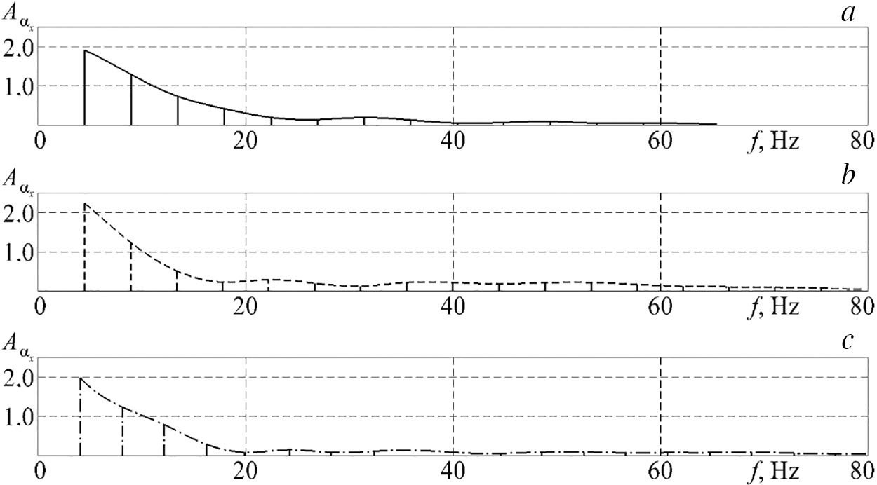
Figure 11: Graphs of the spectrum amplitudes of the local HTC Аαx in supply systems with valve channels having different cross–sectional shapes at n = 600 min−1: a–(●); b–(■); c–(▲)
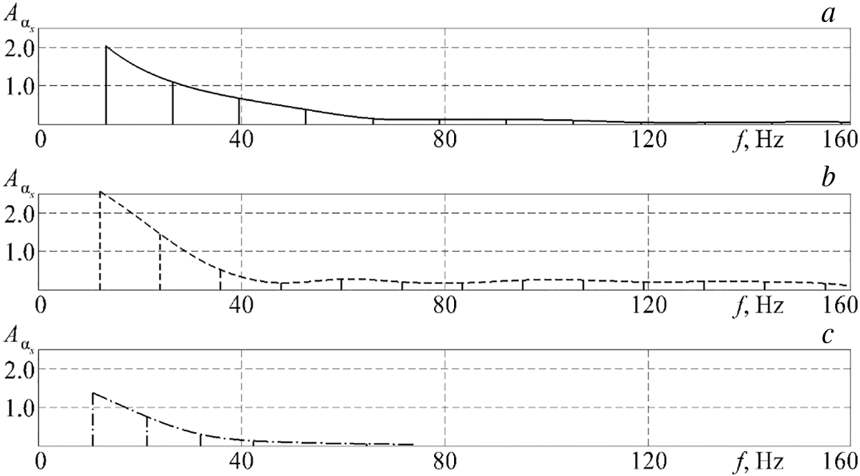
Figure 12: Graphs of the spectrum amplitudes of the local HTC Аαx in supply systems with valve channels having different cross–sectional shapes at n = 2100 min−1: a–(●); b–(■); c–(▲)
As expected, the first significant frequency has the maximum relative pulsation amplitude αx and corresponds to the shaft rotation frequency divided in half (Fig. 11). A noticeable change in the amplitude graphs of the spectra stretches up to 60 Hz at n = 600 min−1 (further significant amplitudes become negligible). An increase in the rotation frequency n causes an expansion of the change in the spectrum amplitude graph to 120–160 Hz (XTC pulsations are amplified). The pulsation amplitudes Аαx decrease linearly with increasing pulsation frequencies f. The amplitude spectrum multiplicity αx is about 5 Hz. The spectrum decays at f > 20 Hz for n = 600 min−1. The largest number of insignificant pulsation amplitudes is characteristic of the square valve channel (Fig. 11b).
An increase in shaft rotation speed n to 2100 rpm led to an increase in the frequency of significant amplitudes of HTC pulsations to 80 Hz for round and square valve channels (Fig. 12a,b). In this case, significant pulsation amplitudes αx decay in the region of f ≈ 45 Hz when using a triangular valve channel in the supply system of the reciprocating-ICE model (Fig. 12c). It should be noted that the pulsations relative amplitude Aαx has the greatest value for the square valve channel (the difference is about 12% compared to the base channel), and Aαx has the smallest value for the triangular channel (the difference is about 30% compared to the base channel). The largest number of insignificant pulsation amplitudes is also characteristic of the square valve channel (Fig. 12b).
The obtained data indicate that further studies of instantaneous heat transfer of unsteady air flows in valve channels with different CSSs are necessary to better understand the physical phenomena occurring in them.
The main conclusions of this study are as follows:
1. The impact of the CSSs of the valve channel on the gas dynamics and heat exchange of unsteady flows in the supply system of a reciprocating-engine model was studied.
2. Experimental data on the change in local speed and instantaneous HTC in time for a full cycle of a four-stroke ICE model for different crankshaft rotation speeds were obtained; an analysis of patterns and trends was performed.
3. Figured valve channels lead to an increase in volumetric air flow through the supply system by 12–32% compared to the basic configuration; the application of figured valve channels results in an increase in volumetric efficiency by an average of 17%.
4. The change in the Nusselt number from the Reynolds number is calculated for unsteady flows in the supply system for the base and figured valve channels; a triangular valve channel leads to the intensification of heat transfer (up to 18%) compared to the basic supply system, and the use of a square valve channel suppresses heat transfer (up to 15%). The opposite effect can be explained by the different strengths of the secondary currents and the different volumes of the valve channels.
5. Diagrams of the spectrum amplitudes of the local HTC in supply systems with figured valve channels were obtained; an analysis of the power and magnitude of heat transfer pulsations was carried out.
The obtained data are applicable for the modernization of the supply and discharge systems of reciprocating machines to improve their operational performance. The results also contribute to the advancement of knowledge in the field of non-stationary thermal physics and gas dynamics of flows. Further plans include testing real ICEs with figured valve channels. Obtaining data on the specific fuel consumption, power, and torque of a reciprocating-engine is an extremely important task.
Acknowledgement: The work has been supported by the Russian Science Foundation.
Funding Statement: The work has been supported by the Russian Science Foundation (Grant No. 23-29-00022).
Author Contributions: The authors confirm contribution to the paper as follows: study conception and design: Leonid Plotnikov; data collection: Danil Davydov, Dmitry Krasilnikov; analysis and interpretation of results: Leonid Plotnikov, Vladislav Shurupov; draft manuscript preparation: Leonid Plotnikov, Vladislav Shurupov. All authors reviewed the results and approved the final version of the manuscript.
Availability of Data and Materials: The data that supports the findings of this study are available from the author upon reasonable request.
Ethics Approval: Not applicable.
Conflicts of Interest: The authors declare that they have no conflicts of interest to report regarding the present study.
References
1. Stone R. Introduction to internal combustion engines. London: Macmillan; 1999. [Google Scholar]
2. Zhou Y, Li X, Ding S, Zhao S, Zhu K, Shao L, et al. Technologies and studies of gas exchange in two-stroke aircraft piston engine: a review. Chinese J Aero. 2024;37(1):24–50. doi:10.1016/j.cja.2022.08.012. [Google Scholar] [CrossRef]
3. Hu B, Akehurst S, Brace C. Novel approaches to improve the gas exchange process of downsized turbocharged spark-ignition engines: a review. Int J Eng Res. 2016;17(6):595–618. doi:10.1177/1468087415599866. [Google Scholar] [CrossRef]
4. Silva EAA, Ochoa AAV, Henríquez JR. Analysis and runners length optimization of the intake manifold of a 4-cylinder spark ignition engine. Energ Conv Manag. 2019;188:310–20. doi:10.1016/j.enconman.2019.03.065. [Google Scholar] [CrossRef]
5. Jiang F, Li M, Wen J, Tan Z, Zhou W. Optimization analysis of engine intake system based on coupling matlab-simulink with GT-power. Math Probl Eng. 2021;2021:6673612. doi:10.1155/2021/6673612. [Google Scholar] [CrossRef]
6. Song Y, Xu Y, Cheng X, Wang Z, Zhu W, Fan X. Using a genetic algorithm to achieve optimal matching between PMEP and diameter of intake and exhaust throat of a high-boost-ratio engine. Energies. 2022;15(5):1607. doi:10.3390/en15051607. [Google Scholar] [CrossRef]
7. Jiang F, Cao W, Tan X, Hu J, Zhou J, Tan Z. Optimization analysis of locomotive diesel engine intake system based on matlab-simulink and GT-power. Processes. 2022;10(1):157. doi:10.3390/pr10010157. [Google Scholar] [CrossRef]
8. Wang G, Yu W, Li X, Su Y, Yang R, Wu W. Study on dynamic characteristics of intake system and combustion of controllable intake swirl diesel engine. Energy. 2019;180:1008–18. doi:10.1016/j.energy.2019.05.162. [Google Scholar] [CrossRef]
9. Ichiyanagi M, Saito R, Sawamura Y, Ndizeye G, Gotama GJ, Anggono W, et al. Effects of intake flow on in-cylinder swirl flow under motoring and firing conditions for CI engines using PIV measurements. J Eng Sci Technol. 2021;16(5):3600–19. [Google Scholar]
10. Zhao X, Liu R, Zheng Z, Chen P, Wang H, Zhou G, et al. The interaction of charge motion and EGR on anti-knock performance and efficiency of a medium-duty gasoline engine: an experimental study. Int J Eng Res. 2024;25(4):705–16. doi:10.1177/14680874231203738. [Google Scholar] [CrossRef]
11. Ichiyanagi M, Yilmaz E, Hamada K, Hara T, Anggono W, Suzuki T. Experimental investigation of the in-cylinder flow of a compression ignition optical engine for different tangential port opening areas. Energies. 2023;16(24):8110. doi:10.3390/en16248110. [Google Scholar] [CrossRef]
12. Li B, He Y-P, Qian Z-Y, Hu J, Zheng H, Ma J, et al. Research on performance matching of intake and exhaust ports of marine medium speed dual fuel engine. Energ Rep. 2021;7(3):72–83. doi:10.1016/j.egyr.2021.02.020. [Google Scholar] [CrossRef]
13. Ikhtiar U, Hairuddin AAB, Asarry AB, Rezali KAB, Ali HM, Jalal RIA. Experimental assessment of lamella heat exchanger as cold intake air system for spark ignition engine by utilizing vehicle air conditioning system. Int Com Heat and Mass Transfer. 2023;148:106989. doi:10.1016/j.icheatmasstransfer.2023.106989. [Google Scholar] [CrossRef]
14. Siqueira Mazzaro R, de Morais Hanriot S, Jorge Amorim R, Américo Almeida Magalhães Júnior P. Numerical analysis of the air flow in internal combustion engine intake ducts using Herschel-Quincke tubes. Appl Acoust. 2020;165(18):107310. doi:10.1016/j.apacoust.2020.107310. [Google Scholar] [CrossRef]
15. Xie J, Liu Z. Structural optimization on the design of an automobile engine intake pipe. J Theor Appl Mech. 2022;60(3):449–61. doi:10.15632/jtam-pl/151069. 2022. [Google Scholar] [CrossRef]
16. Karthikeyan K, Divine SA, Jibin J, Thomas SJ. CFD analysis of air intake manifold system to improve the efficiency of student formula car. Int J Vehicle Struct Syst. 2023;15(6):833–5. doi:10.4273/ijvss.15.6.18. [Google Scholar] [CrossRef]
17. Li J, Deng Z, Ran C. Research on the structure optimization design of automobile intake pipe. Appl Sci. 2023;13(11):6505. doi:10.3390/app13116505. [Google Scholar] [CrossRef]
18. Yang S, Yan K, Liu H, Fu Y, Liu H, Li T. 3-dimentional numerical transient simulation and research on flow distribution unevenness in intake manifold for a turbocharged diesel engine. SAE Tech Papers. 2024;1:199083. doi:10.4271/2024-01-2420. [Google Scholar] [CrossRef]
19. Bondar V, Aliukov S, Malozemov A, Das A. Mathematical model of thermodynamic processes in the intake manifold of a diesel engine with fuel and water injection. Energies. 2020;13(17):4315. doi:10.3390/en13174315. [Google Scholar] [CrossRef]
20. Kim K-H, Kong K-J. One-dimensional gas flow analysis of the intake and exhaust system of a single cylinder diesel engine. J Marine Sci Eng. 2020;8(12):1036. doi:10.3390/jmse8121036. [Google Scholar] [CrossRef]
21. Kumar V, Goswami S, Smith D, Karniadakis GE. Real-time prediction of gas flow dynamics in diesel engines using a deep neural operator framework. Appl Intell. 2024;54(1):14–34. doi:10.1007/s10489-023-05178-z. [Google Scholar] [CrossRef]
22. Luján JM, Climent H, García-Cuevas LM, Moratal A. Volumetric efficiency modelling of internal combustion engines based on a novel adaptive learning algorithm of artificial neural networks. Appl Therm Eng. 2017;123:625–34. doi:10.1016/j.applthermaleng.2017.05.087. [Google Scholar] [CrossRef]
23. Pulpeiro González J, Ankobea-Ansah K, Peng Q, Hall CM. On the integration of physics-based and data-driven models for the prediction of gas exchange processes on a modern diesel engine. Proc Inst Mech Eng Part D: J Autom Eng. 2022;236(5):857–71. doi:10.1177/09544070211031401. [Google Scholar] [CrossRef]
24. Hautala S, Mikulski M, Söderäng E, Storm X, Niemi S. Toward a digital twin of a mid-speed marine engine: from detailed 1D engine model to real-time implementation on a target platform. Int J Eng Res. 2023;24(12):4553–71. doi:10.1177/14680874221106168. [Google Scholar] [CrossRef]
25. Dai Z, Li J, Liang H, Yu X, Wu B. Experimental study on the transient-state performance of diesel engines at different speeds using the synergistic regulation of VGT and VVT. Int J Eng Res. 2024;25(5):959–70. doi:10.1177/14680874231214300. [Google Scholar] [CrossRef]
26. Nath K, Meng X, Smith DJ, Karniadakis GE. Physics-informed neural networks for predicting gas flow dynamics and unknown parameters in diesel engines. Sci Rep. 2023;13(1):13683. doi:10.48550/arXiv.2304.13799 [Google Scholar] [PubMed] [CrossRef]
27. Mazuro P, Kozak D. Experimental investigation on the performance of the prototype of aircraft Opposed-Piston engine with various values of intake pressure. Energy Convers Manag. 2022;269(8):116075. doi:10.1016/j.enconman.2022.116075. [Google Scholar] [CrossRef]
28. Paranjape S, Thakur S, Emran A, Wagh S, Sharma V. Intake and exhaust system optimization of a single cylinder engine using 1D simulation approach. SAE Tech Papers. 2024;1:197403. doi:10.4271/2024-26-0212. [Google Scholar] [CrossRef]
29. Hirota M, Fujita H, Yokosawa H. Turbulent heat transfer in a square duct. Int J Heat and Fluid Flow. 1997;18(1):170–80. doi:10.1016/S0142-727X(96)00151-8. [Google Scholar] [CrossRef]
30. Rapley CW, Gosman AD. The prediction of turbulent flow and heat transfer in a narrow isosceles triangular duct. Int J Heat and Mass Transfer. 1984;27(2):253–62. doi:10.1016/0017-9310(84)90216-3. [Google Scholar] [CrossRef]
31. Plotnikov L, Plotnikov I, Osipov L, Slednev V, Shurupov V. An indirect method for determining the local heat transfer coefficient of gas flows in pipelines. Sensors. 2022;22(17):6395. doi:10.3390/s22176395 [Google Scholar] [PubMed] [CrossRef]
32. Plotnikov L. A thermal anemometry method for studying the unsteady gas dynamics of pipe flows: development, modernisation, and application. Sensors. 2023;23(24):9750. doi:10.3390/s23249750 [Google Scholar] [PubMed] [CrossRef]
33. Bradshaw P. Introduction to turbulence and its measurement. Moscow: Energoatomizdat; 1974 (In Russian). [Google Scholar]
34. Lomas CG. Fundamentals of hot wire anemometry. Cambridge: Cambridge University Press; 2011. [Google Scholar]
35. Plotnikov LV. Preparation and analysis of experimental findings on the thermal and mechanical characteristics of pulsating gas flows in the intake system of a piston engine for modelling and machine learning. Mathematics. 2023;11(8):1967. doi:10.3390/math11081967. [Google Scholar] [CrossRef]
36. Plotnikov LV. Unsteady gas dynamics and local heat transfer of pulsating flows in profiled channels mainly to the intake system of a reciprocating engine. Int J Heat and Mass Transfer. 2022;195:123144. doi:10.1016/j.ijheatmasstransfer.2022.123144. [Google Scholar] [CrossRef]
37. Pu Y-H, Dierickx J, Verhelst S. Modelling the evaporative cooling effect from methanol injection in the intake of internal combustion engines. Fuel. 2024;372:132131. doi:10.1016/j.fuel.2024.132131. [Google Scholar] [CrossRef]
38. Yuan B, Wang Z, Cao J, Huang Y, Shen Y, Song Z, et al. Mixture formation characteristics and feasibility of methanol as an alternative fuel for gasoline in port fuel injection engines: droplet evaporation and spray visualization. Energy Convers Manag. 2023;283:116956. doi:10.1016/j.enconman.2023.116956. [Google Scholar] [CrossRef]
Cite This Article
 Copyright © 2024 The Author(s). Published by Tech Science Press.
This work is licensed under a Creative Commons Attribution 4.0 International License , which permits unrestricted use, distribution, and reproduction in any medium, provided the original work is properly cited.


 Submit a Paper
 Propose a Special lssue
 View Full Text
 Download PDF
 Downloads
 Citation Tools