 Open Access
ARTICLE
Experimental Analyses of Flow Pattern and Heat Transfer in a Horizontally Oriented Polymer Pulsating Heat Pipe with Merged Liquid Slugs
1 Department of Mechanical and Mathematical Engineering, Graduate School of Science and Technology, Kumamoto University, Kumamoto, 860-8555, Japan
2Division of Industrial Fundamentals, Faculty of Advanced Science and Technology, Kumamoto University, Kumamoto, 860-8555, Japan
* Corresponding Author: Yasushi Koito. Email:
Frontiers in Heat and Mass Transfer 2024, 22(5), 1381-1397. https://doi.org/10.32604/fhmt.2024.056624
Received 26 July 2024; Accepted 08 October 2024; Issue published 30 October 2024
Abstract
Extended experiments were conducted on the oscillation characteristics of merged liquid slugs in a horizontally oriented polymer pulsating heat pipe (PHP). The PHP’s serpentine channel comprised 14 parallel channels with a width of 1.3 and a height of 1.1 . The evaporator and condenser sections were 25 and 50 long, respectively, and the adiabatic section in between was 75 mm long. Using a plastic 3D printer and semi-transparent filament made from acrylonitrile butadiene styrene, the serpentine channel was printed directly onto a thin polycarbonate sheet to form the PHP. The PHP was charged with hydrofluoroether-7100. In the experiments, the evaporator section was heated, and the condenser section was cooled using high-temperature and low-temperature thermostatic baths, respectively. Flow patterns of the working fluid were obtained with temperature distributions of the PHP. A mathematical model was developed to analyze the flow patterns. The merged liquid slugs were observed in every two channels, and their oscillation characteristics were found to be approximately the same in time and space. It was also found that the oscillations of the merged liquid slugs became slower, but the heat transfer rate of the PHP increased with a decrease in the filling ratio of the working fluid. This is because vapor condensation was enhanced in vapor plugs as the filling ratio decreased. However, the filling ratio had a lower limit, and the heat transfer rate was maximum when the filling ratio was 40.6% in the present experimental range.Keywords
Nomenclature
| Amplitude ( | |
| Specific heat ( | |
| Frequency ( | |
| Length ( | |
| Mass ( | |
| Mass flow rate ( | |
| Polytropic index | |
| Pressure ( | |
| Heat transfer rate ( | |
| Temperature (°C) | |
| Time ( | |
| Filling ratio (%) | |
| Velocity ( | |
| Coordinate, Position ( | |
| Local coordinate, Position ( | |
| Greek Symbols | |
| Time difference ( | |
| Initial phase ( | |
| Viscosity ( | |
| Angular frequency ( | |
| Superscripts | |
| Initial | |
| Condenser side, decreasing | |
| Evaporator side, increasing | |
| Center | |
| Subscripts | |
| Position | |
| Adiabatic section | |
| Condenser section | |
| Evaporator section | |
| i th | |
| Inlet | |
| Liquid slug | |
| Outlet | |
| Vapor plug | |
| Cooling water | |
The pulsating heat pipe (PHP) is a wickless heat pipe that was invented by Akachi [1] in 1990. The PHP transports heat passively by using a self-induced oscillatory flow of a working fluid, which essentially differs from traditional heat pipes with capillary wick structures (e.g., [2–6]). The PHP is a promising candidate for thermal management, and thus, a great deal of studies have been conducted on the PHP as reviewed in previous articles (e.g., [7–11]). Although the review contents differ between these articles [7–11], they all state that the PHP is a promising candidate for thermal management, especially in electronics cooling. Recently, polymer materials have been used for fabricating the PHPs. As mentioned in our previous papers [12,13], polydimethylsiloxane [14], polyethylene [15], polytetrafluoroethylene [16], and polypropylene [17] were used as the materials of polymer PHPs. In addition, Arai et al. [18] conducted experiments to investigate the heat transfer characteristics of a polymer PHP, which comprised a polycarbonate serpentine channel and an aluminum plate. The PHP was filled with hydrofluoroether (HFE)-7000 as a working fluid, and the effects of the flow channel size and fill ratio of the working fluid on the PHP’s heat transport performance were investigated. Candere et al. [19] proposed the fabrication of a polymer PHP using a common stereolithography technology. FC-72 was used as a working fluid. It was shown that the effective thermal conductivity of the polymer PHP was more than one thousand times higher than the thermal conductivity of a polymer sheet at a 30
Orientation is one of the important factors affecting the thermal performance of the PHPs. Many studies have been conducted in a bottom-heated vertical orientation mode [20–24]. However, it was reported that the thermal performance of the PHPs changed when the orientation was changed from vertical to horizontal. Thompson et al. [25] experimentally investigated the thermal performance of a three-dimensional flat-plate PHP with staggered microchannels using water and acetone as working fluids. It was found that the thermal performance of the PHP in a vertical orientation was better than that in a horizontal orientation. Chien et al. [26] showed that the thermal performance of a copper-water PHP decreased as the PHP’s inclination changed from vertical to horizontal. Less orientation dependence was observed for the PHP with dual-diameter channels compared with the PHP with uniform channels. Jun et al. [27] experimentally compared the thermal performance and flow characteristics between closed-loop and closed-end micro-PHPs. The PHP channels were engraved on a silicon wafer using MEMS techniques, and ethanol was employed as a working fluid. It was shown that, in the case of the PHP with 10 and 15 turns, the thermal performance of the closed-loop PHP deteriorated significantly as the PHP’s inclination changed from vertical to horizontal. In contrast, the closed-end PHP operated stably regardless of the PHP’s inclination. Jung et al. [28] investigated the thermal performance of a PHP with a passive check valve in vertical and horizontal orientations. It was reported that the thermal performance of the PHP in the vertical orientation was better than that in the horizontal orientation. Dixit et al. [29] developed a cryogenic stainless PHP using neon as a working fluid. The lowest thermal resistance of the PHP was 0.17
The above-mentioned ABS PHP using HFE-7100 was also affected by the orientation. That is, differing from flow patterns in a vertical orientation, an oscillatory flow of merged liquid slugs was observed in a horizontal orientation [30]. This is a unique characteristic of the ABS PHP, but the details have not been discussed. Because of this, extended experiments were conducted in the present study regarding the oscillation characteristics of the merged liquid slugs in the horizontally oriented PHP. A semi-transparent ABS PHP was employed with HFE-7100. Flow patterns of the merged liquid slugs were obtained along with temperature distributions of the PHP. A mathematical model was developed to analyze the flow patterns. The oscillation characteristics were discussed based on the analytical results of the flow patterns. Discussion was also conducted on the effect of the filling ratio of the working fluid on the oscillation and the heat transfer characteristics of the PHP.
Fig. 1 shows a schematic diagram of the PHP. This is the same PHP as in our previous study [13], in which experiments were conducted in a vertical orientation mode. Because the design and fabrication method of the PHP including 3D printing and material selection were already described in our previous paper [13], only their brief overview is presented here. As shown in Fig. 1a, a serpentine channel of the PHP comprised 14 parallel channels with a width of 1.3
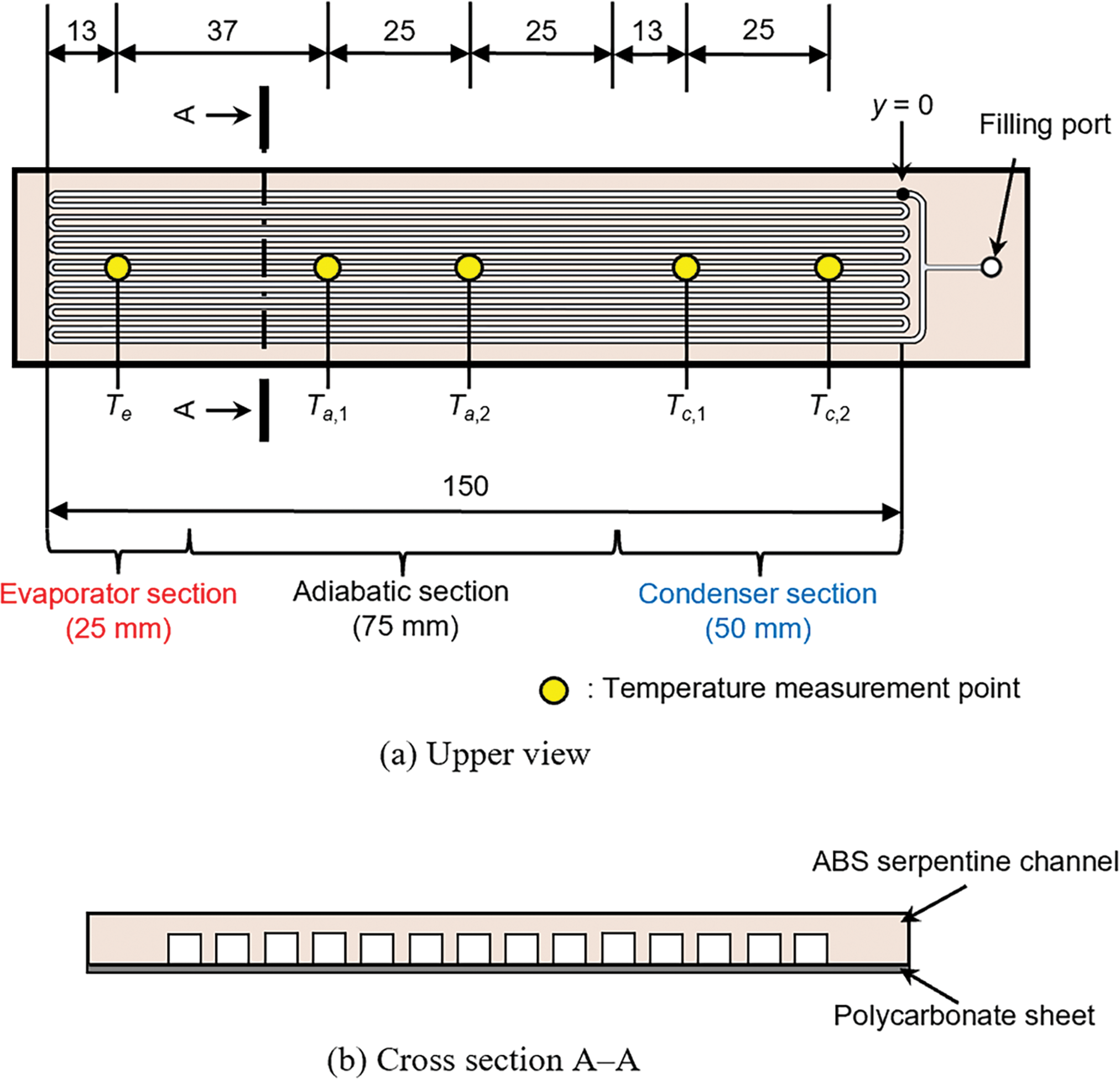
Figure 1: Schematic diagram of the PHP (unit:
Fig. 2 shows a schematic diagram of the experimental apparatus. Heating and cooling jackets were mounted at the evaporator and condenser sections, respectively, of the PHP on the polycarbonate sheet side. Thermal grease was used between the polycarbonate sheet and the jackets. The heating and cooling jackets were piped to high-temperature and low-temperature thermostatic baths, respectively. A vacuum pump and a pressure transducer were employed to evacuate air from inside the PHP. A high-speed camera was placed above the PHP with lighting devices; fluid flow phenomena in the PHP were captured through the semi-transparent ABS wall of the serpentine channel. Except for the heated and cooled sections, the rest of the PHP was covered with a thermal insulation material to reduce heat loss. Figs. 1 and 2 also show temperature measurement points. T-type thermocouples were attached at the evaporator (
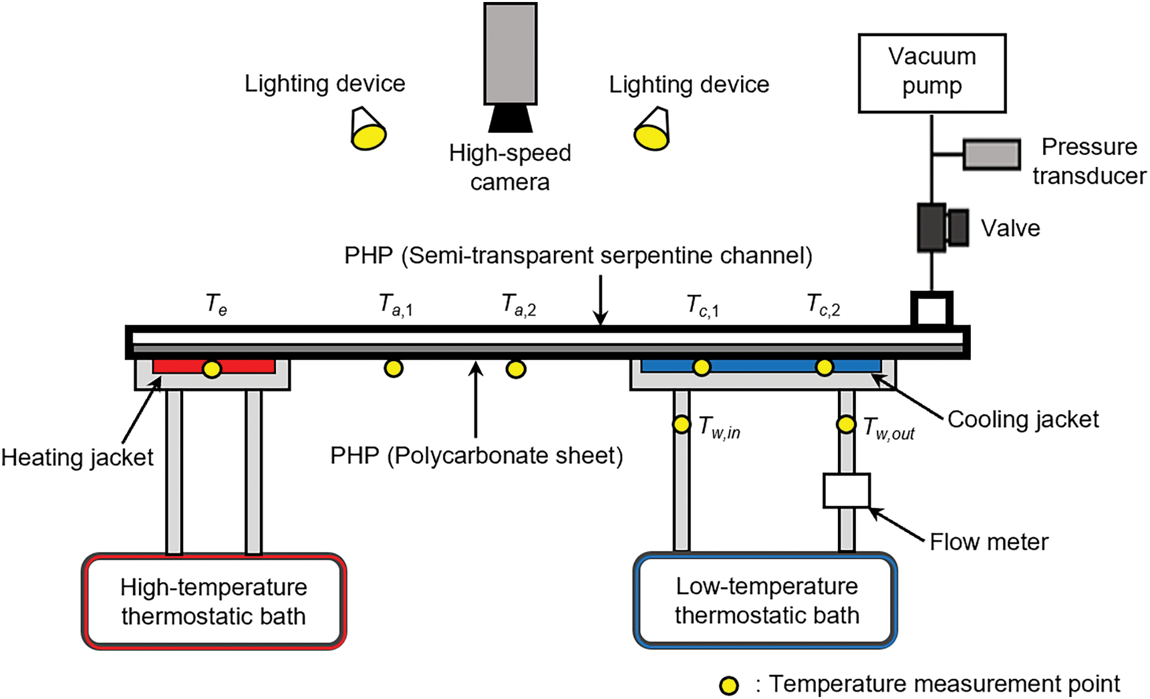
Figure 2: Schematic diagram of the experimental apparatus
where
The PHP was charged with HFE-7100. The representative physical properties of HFE-7100 were shown in the previous paper [31]. Fig. 3 shows schematic diagrams of working fluid distribution states in the PHP. The working fluid was distributed in the form of liquid slugs and vapor plugs, which are shown by using dark and light colors, respectively. Fig. 3a is a distribution state immediately after filling the PHP with the working fluid. Liquid slugs and vapor plugs were well distributed throughout the PHP channel. However, this distribution was greatly affected by gravity [30]. That is, when the PHP was oriented vertically, the liquid slugs flowed down, and the vapor plugs flowed up resulting in a distribution state where the liquid slugs and vapor plugs were completely separated. The PHP channel was designed based on the Bond number, which is the ratio of gravitational force to surface tension force. When the working fluid was changed from HFE-7100 to water, a well-distributed state like Fig. 3a was maintained under the same Bond number, which implies that the influence of the gravitational force was different between HFE-7100 and water. The influence was significant for HFE-7100, and thus unique oscillation characteristics of merged liquid slugs were observed in the present PHP. From the distribution state of Fig. 3a, the liquid volumes in each PHP channel were adjusted by tilting the PHP forward, backward, left, and right so that the lengths of all long liquid slugs were approximately the same. Thereafter, the PHP was oriented horizontally, and the distribution state shown in Fig. 3b was obtained. Long liquid slugs were located on the condenser side while the evaporator side was occupied by long vapor plugs. The experiment was started from this distribution state. The cooling jacket was cooled with cooling water, and then heating water was supplied to the heating jacket. Immediately after that, the PHP was tilted slightly for a short time, which started the oscillations of long liquid slugs and long vapor plugs, and the distribution state shown in Fig. 3c was obtained. The heating and cooling were conducted at approximately
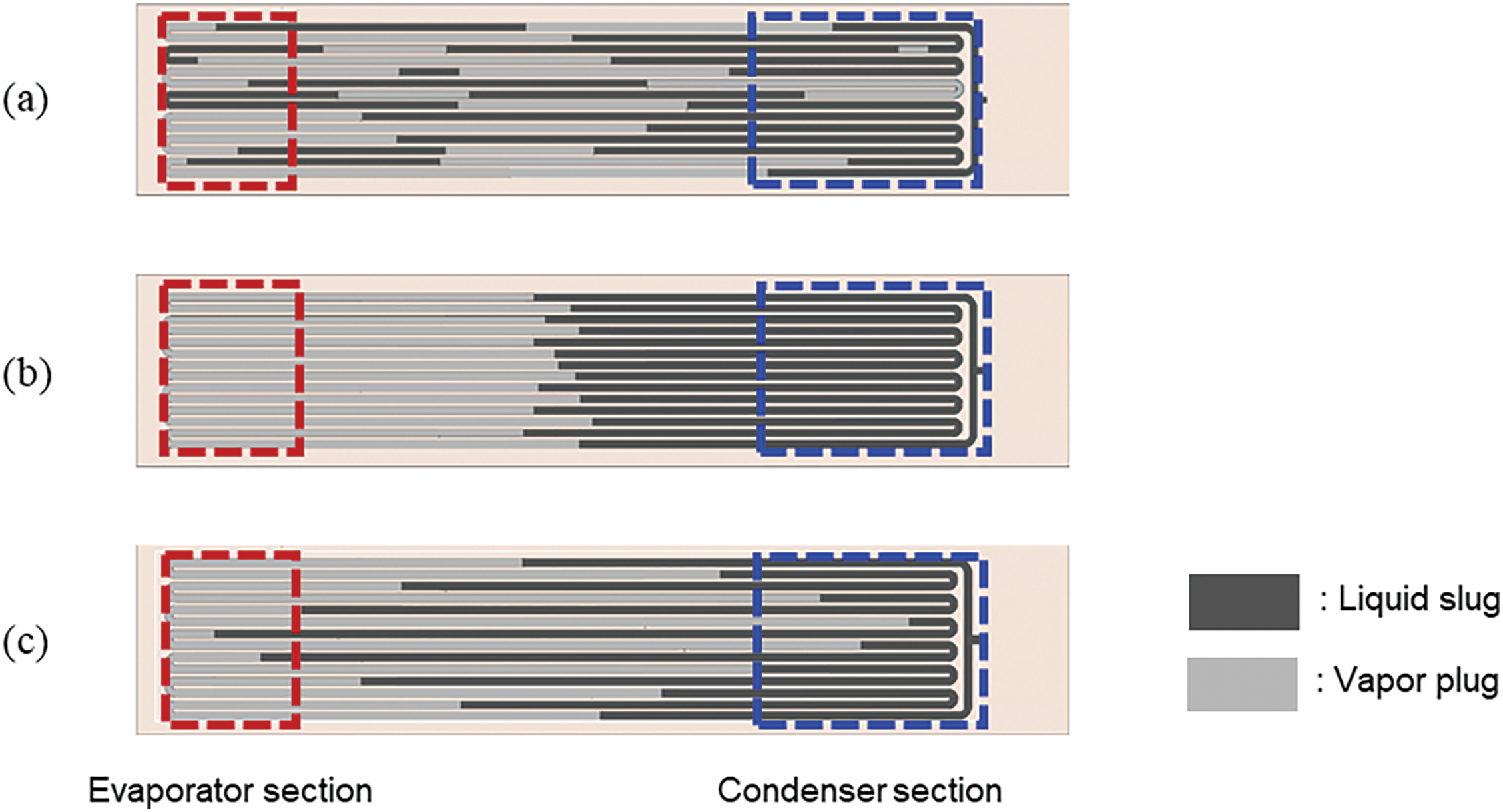
Figure 3: Schematic diagrams of working-fluid distribution states (a: distribution state immediately after filling the PHP with the working fluid, b: distribution state just before starting the experiment, c: distribution state when the PHP is operating)
3.1 Fluid Flow Characteristics
Fig. 4 shows flow patterns in all channels of the PHP when the filling ratio (
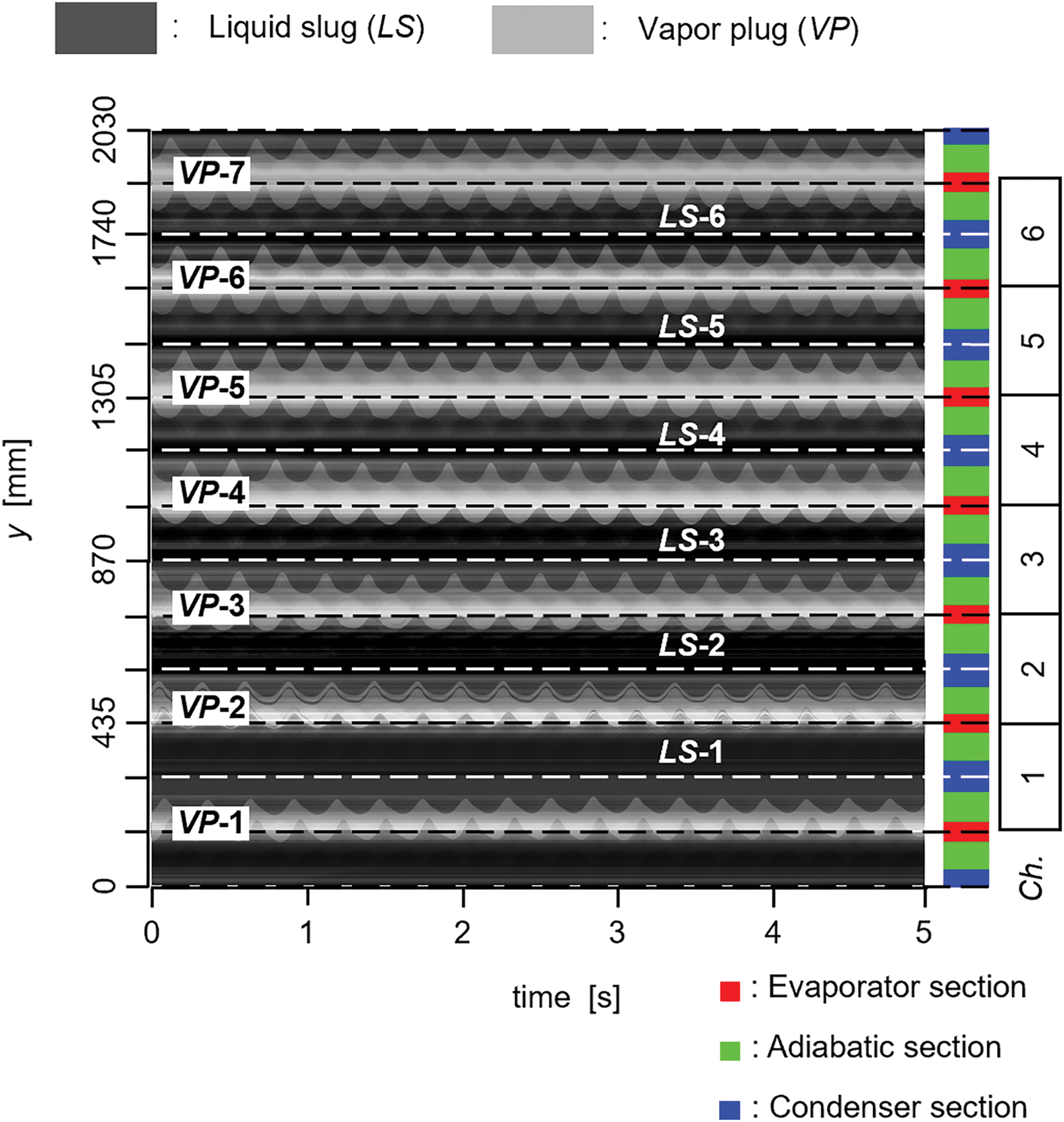
Figure 4: Flow patterns in all channels of the PHP (
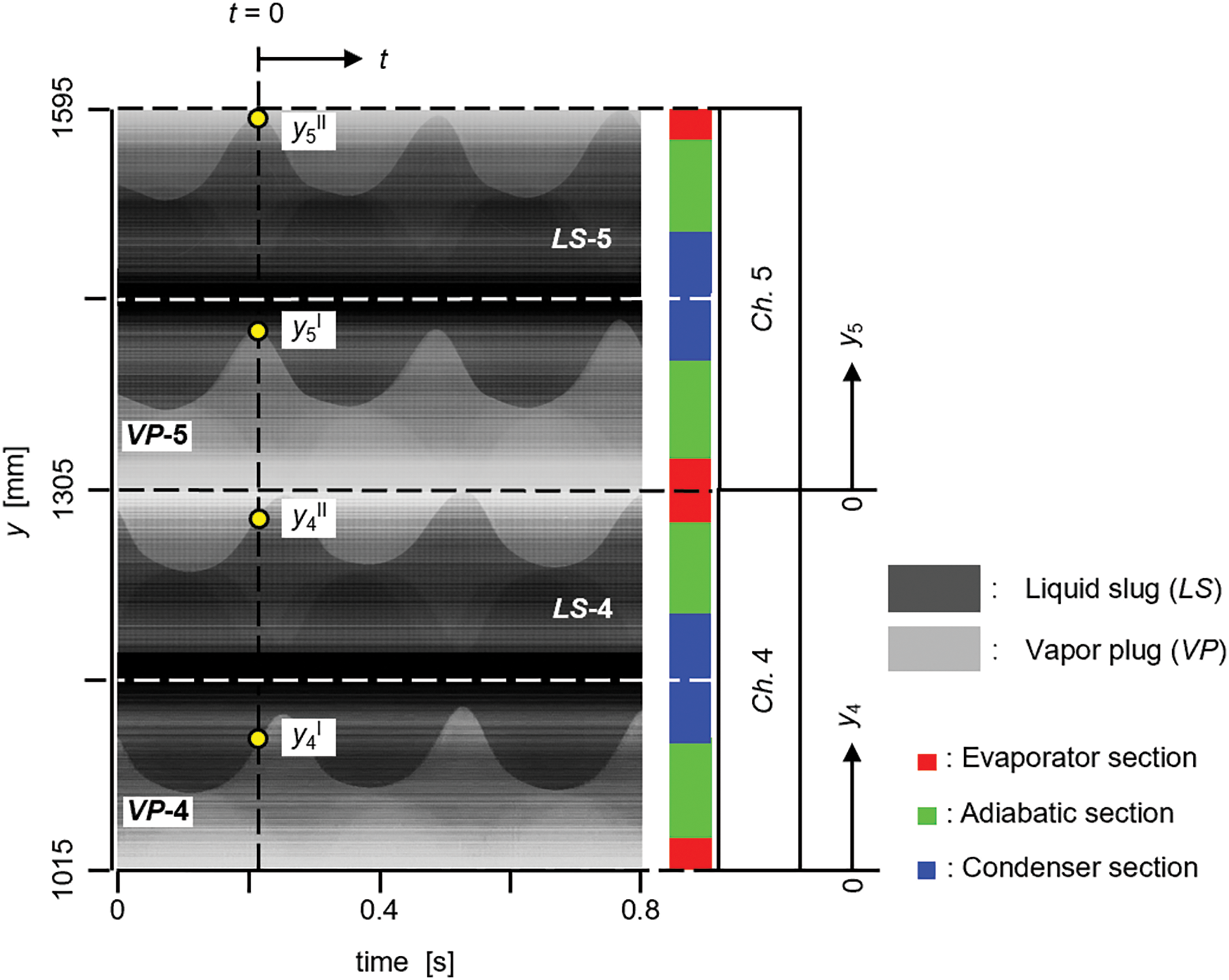
Figure 5: Enlarged view of the flow patterns in Ch. 4 and 5 (
Fig. 6 shows the
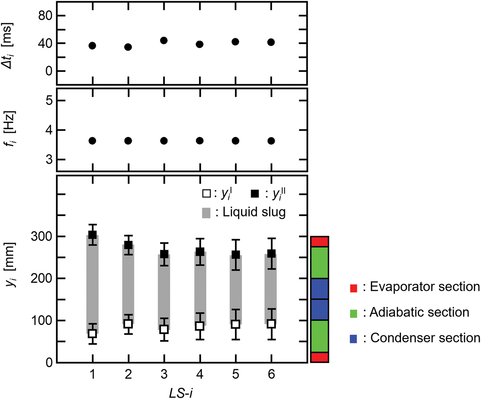
Figure 6: Oscillation characteristics of the long liquid slugs (LS-1 to LS-6,
The average values of
For VP-5 in Fig. 5, the temporal change in the length of VP-5 (lVP-5) was obtained as shown in Fig. 7. Fig. 7a is the flow pattern of VP-5, and Fig. 7b shows the change in lVP-5. Because of the periodicity, the change only in one period is shown, and
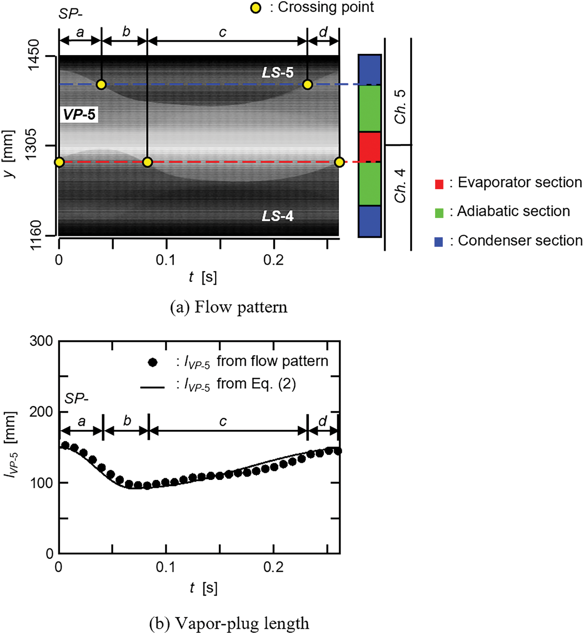
Figure 7: Temporal change in the vapor-plug length (VP-5,
The following empirical equation was proposed to express the length of i th long vapor plug (
where
The values of the four constants (
For the i th long liquid slug, the equation of motion is expressed as
where
When the same polytropic change was assumed for the i and i + 1 th long vapor plugs, Eq. (6) was obtained.
where
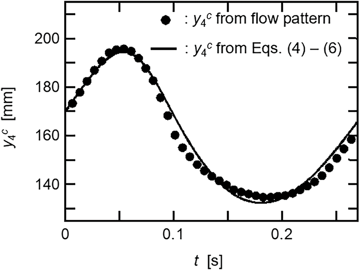
Figure 8: Comparison between the liquid-slug positions obtained from flow pattern and Eqs. (4)–(6) (LS-4,
From Eqs. (4)–(6), temporal changes in the net force acting on LS-4 and the velocity of LS-4 were numerically obtained as shown in Fig. 9a,b, respectively. The net force was expressed by the right side of Eq. (4), and the numerical result was also shown in Fig. 9a when the frictional force was neglected in Eq. (4). The frictional force acts in the opposite direction to the velocity, and thus the net force with the frictional force was less than that without the frictional force when the velocity was positive. Conversely, the net force with the frictional force was greater than that without the frictional force when the velocity was negative. Since a difference was found between the two net forces, the frictional force was considered in Eq. (4).
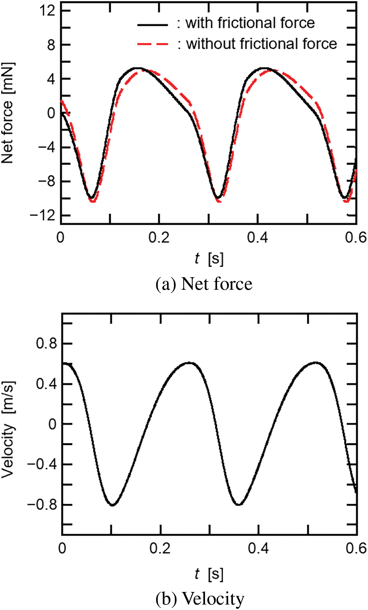
Figure 9: Effect of the frictional force on the net force and velocity of the long liquid slug (LS-4,
Fig. 10 shows the oscillation characteristics of a long liquid slug when the filling ratio (
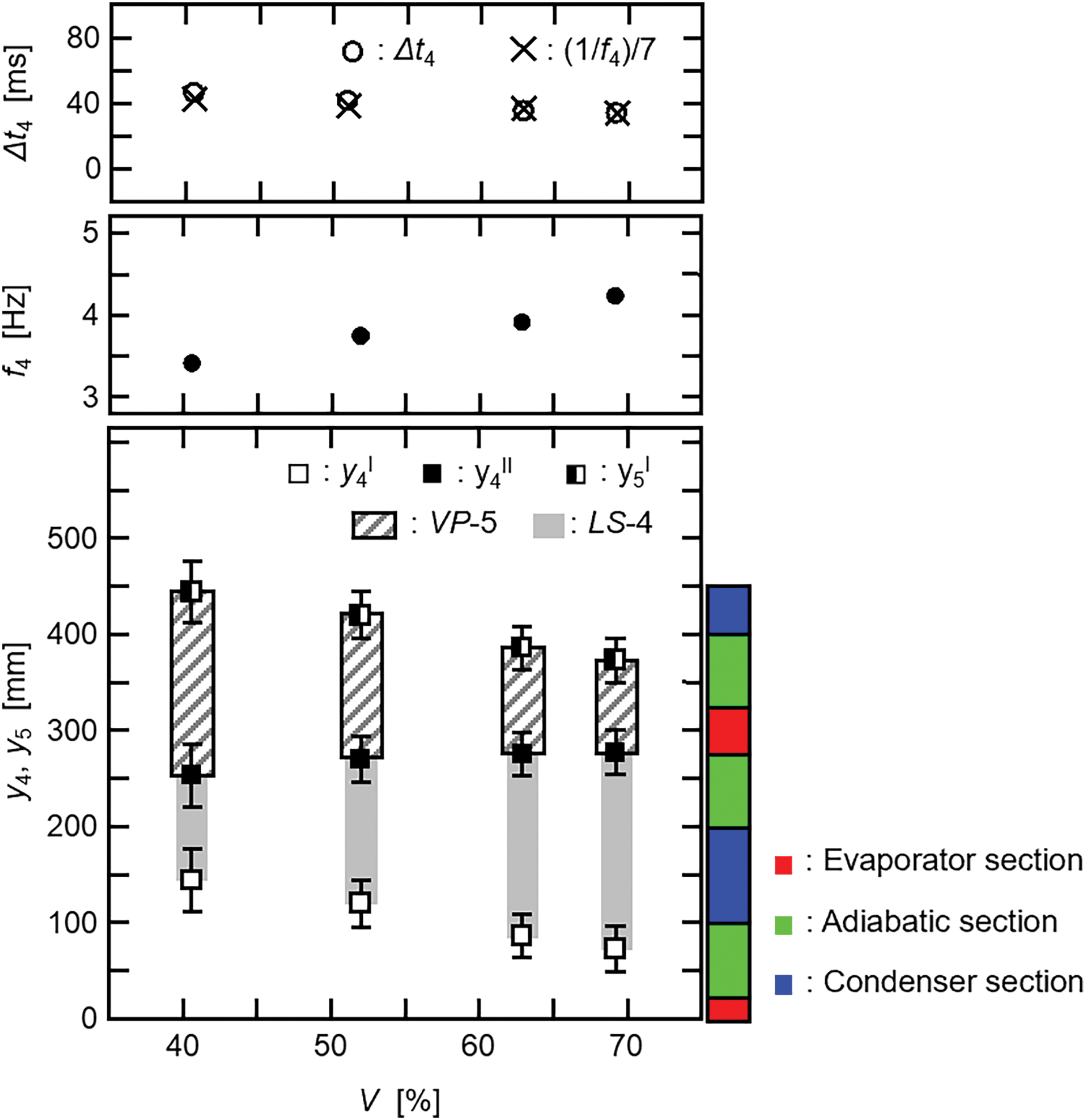
Figure 10: Effect of the filling ratio on the oscillation characteristics of the long liquid slug (LS-4)
For
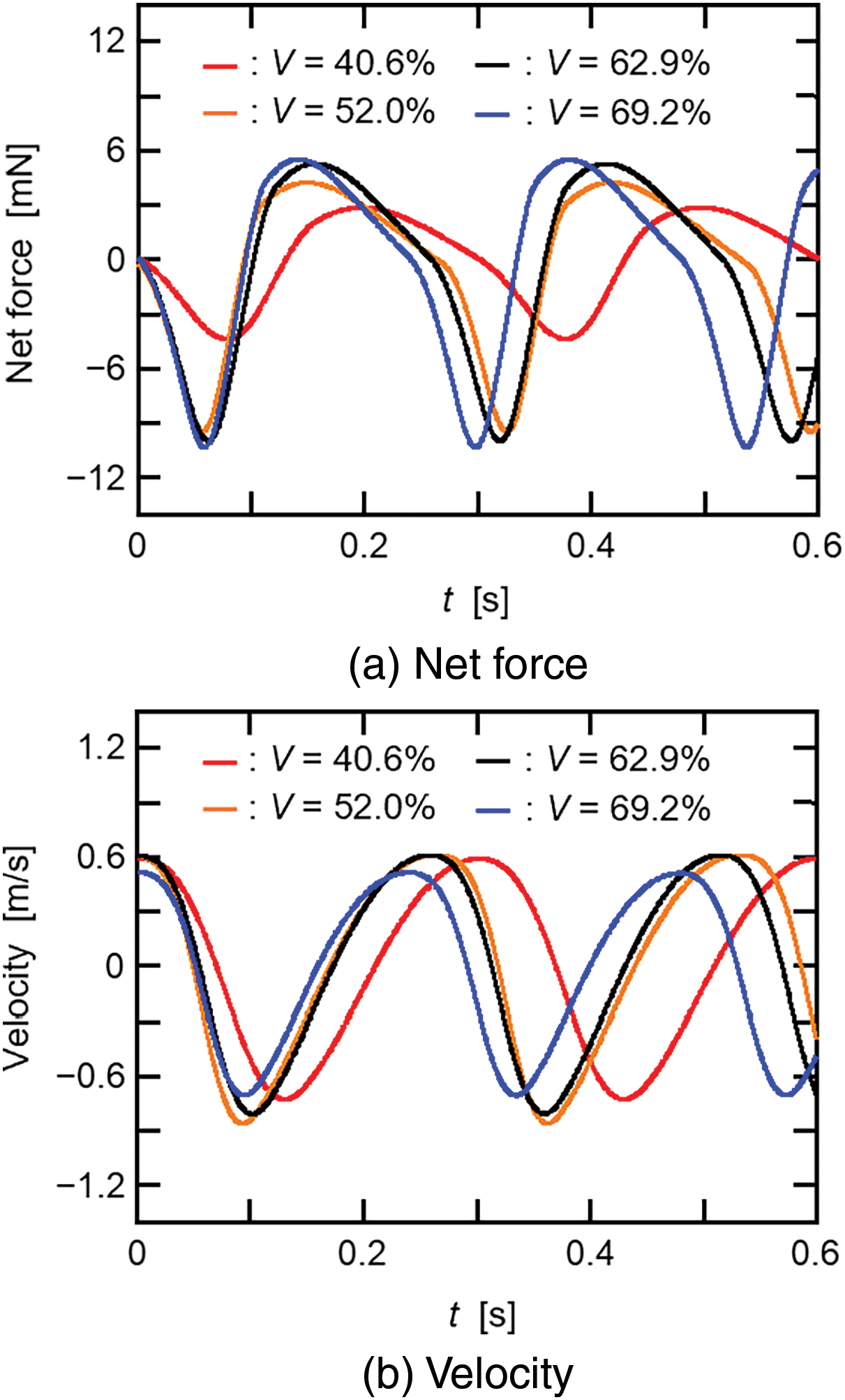
Figure 11: Effect of the filling ratio on the net force and velocity of the long liquid slug (LS-4)
Table 1 shows the heat transfer rate (

Extended experiments were conducted on the oscillation characteristics of merged liquid slugs in the horizontally oriented polymer PHP with HFE-7100 working fluid. Flow patterns of merged liquid slugs were obtained and then numerically analyzed. The oscillation and heat transfer characteristics at different filling ratios of the working fluid were discussed. The findings are summarized as follows:
• Merged liquid slugs were observed in every two channels, and their oscillation characteristics were found to be approximately the same in time and space.
• The mathematical model was developed on the oscillation characteristics of the merged liquid slug. This model was effective in analyzing the flow patterns.
• Because the condensation of vapor was enhanced in vapor plugs, the oscillations of the merged liquid slugs became slower with a decrease in the filling ratio of the working fluid.
• Heat is transferred from the evaporator section to the condenser section through the vapor plugs. This heat transfer rate was increased by the above-mentioned enhancement of condensation in the vapor plugs, and thus the heat transfer rate of the PHP increased with a decrease in the filling ratio.
• However, the filling ratio had a lower limit, and the heat transfer rate was maximum when the filling ratio was 40.6% in the present experimental range.
• Because of no circulation flow, the thermal performance of the PHP in a horizontal orientation was lower than that in a vertical orientation.
It is considered that the present PHP would be affected by many factors such as the number and size of the PHP channel, and the heating and cooling conditions. Our next step is to examine the influences of these factors. In addition, the influences of gravitational force and surface tension force on the PHP operation are different between the two kinds of working fluids: HFE-7100 and water. Thus, an extended analysis is also a future work to clarify the reason for this difference.
Acknowledgement: The authors thank N. Nagasato, A. Yang, S. Okubo, and Y. Sugano for their help in conducting the experiments.
Funding Statement: This work was supported by JSPS KAKENHI Grant Number 22K03947.
Author Contributions: The authors confirm contribution to the paper as follows: study conception and design: Zhengyuan Pei, Yasushi Koito; data collection: Zhengyuan Pei; analysis and interpretation of results: Zhengyuan Pei, Yasushi Koito; draft manuscript preparation: Zhengyuan Pei, Yasushi Koito. All authors reviewed the results and approved the final version of the manuscript.
Availability of Data and Materials: The data are available from the corresponding author upon reasonable request.
Ethics Approval: Not applicable.
Conflicts of Interest: The authors declare that they have no conflicts of interest to report regarding the present study.
References
1. Akachi H. Structures of a heat pipe. U.S. Patent. 1990;4921041. [Google Scholar]
2. Yin L, Liu H, Liu W. Capillary character and evaporation heat transfer in the wicks of high temperature liquid metal heat pipe. Appl Therm Eng. 2020;175:115284. doi:10.1016/j.applthermaleng.2020.115284. [Google Scholar] [CrossRef]
3. Saygan S, Akkus Y, Dursunkaya Z, Cetin B. Capillary boosting for enhanced heat pipe performance through bifurcation of grooves: numerical assessment and experimental validation. Int Commun Heat Mass Transf. 2022;137:106162. doi:10.1016/j.icheatmasstransfer.2022.106162. [Google Scholar] [CrossRef]
4. Ma Y, Wang X, Yu H, Huang S, Zhang Y, Su GH, et al. Capillary limit of a sodium screen-wick heat pipe. Appl Therm Eng. 2023;232:120972. doi:10.1016/j.applthermaleng.2023.120972. [Google Scholar] [CrossRef]
5. Zhou Z, Wu B, Zhu L, Lu J, Cheng T, Tang Y, et al. Enhanced the capillary performance of the injection molded flexible heat pipe shell by the composite microgroove wicks. Therm Sci Eng Prog. 2024;51:102656. doi:10.1016/j.tsep.2024.102656. [Google Scholar] [CrossRef]
6. Elkholy A, Narvan M, Thompson S, Durfee J, Kempers R. The effect of layer thickness on the geometry and capillary performance of strut-based heat pipe wicks manufactured by laser powder bed fusion. Int J Thermofluids. 2024;21:100543. doi:10.1016/j.ijft.2023.100543. [Google Scholar] [CrossRef]
7. Nazari MA, Ahmadi MH, Ghasempour R, Shafii MB. How to improve the thermal performance of pulsating heat pipes: a review on working fluid. Renew Sust Energ Rev. 2018;91:630–8. doi:10.1016/j.rser.2018.04.042. [Google Scholar] [CrossRef]
8. Bastakoti D, Zhang H, Li D, Cai W, Li F. An overview on the developing trend of pulsating heat pipe and its performance. Appl Therm Eng. 2018;141:305–32. doi:10.1016/j.applthermaleng.2018.05.121. [Google Scholar] [CrossRef]
9. Xu Y, Xue Y, Qi H, Cai W. An updated review on working fluids, operation mechanisms, and applications of pulsating heat pipes. Renew Sust Energ Rev. 2021;144:110995. doi:10.1016/j.rser.2021.110995. [Google Scholar] [CrossRef]
10. Su Z, Hu Y, Zheng S, Wu T, Liu K, Zhu M, et al. Recent advances in visualization of pulsating heat pipes: a review. Appl Therm Eng. 2023;221:119867. doi:10.1016/j.applthermaleng.2022.119867. [Google Scholar] [CrossRef]
11. Fazli M, Mehrjardi SAA, Mahmoudi A, Khademi A, Amini M. Advancements in pulsating heat pipes: exploring channel geometry and characteristics for enhanced thermal performance. Int J Thermofluids. 2024;22:100644. doi:10.1016/j.ijft.2024.100644. [Google Scholar] [CrossRef]
12. Nagasato N, Pei Z, Koito Y. Flow patterns and heat transfer characteristics of a polymer pulsating heat pipe filled with hydrofluoroether. Front Heat Mass Transf. 2024;22(1):49–63. doi:10.32604/fhmt.2024.047502. [Google Scholar] [CrossRef]
13. Koito Y, Yoshida H, Pei Z. An experimental study of a polymer pulsating heat pipe 3D-printed on a thin polymer sheet. Multiphase Sci Technol. 2021;33(4):31–43. doi:10.1615/MultScienTechn.v33.i4. [Google Scholar] [CrossRef]
14. Lin Y, Kang S, Wu T. Fabrication of polydimethylsiloxane (PDMS) pulsating heat pipe. Appl Therm Eng. 2009;29(2–3):573–80. [Google Scholar]
15. Lim J, Kim SJ. Fabrication and experimental evaluation of a polymer-based flexible pulsating heat pipe. Energy Convers Manag. 2018;156:358–64. doi:10.1016/j.enconman.2017.11.022. [Google Scholar] [CrossRef]
16. Hao T, Ma H, Ma X. Heat transfer performance of polytetrafluoroethylene oscillating heat pipe with water, ethanol, and acetone as working fluids. Int J Heat Mass Transf. 2019;131(11–12):109–20. doi:10.1016/j.ijheatmasstransfer.2018.08.133. [Google Scholar] [CrossRef]
17. Der O, Alqahtani AA, Marengo M, Bertola V. Characterization of polypropylene pulsating heat stripes: effects of orientation, heat transfer fluid, and loop geometry. Appl Therm Eng. 2021;184(19):116304. doi:10.1016/j.applthermaleng.2020.116304. [Google Scholar] [CrossRef]
18. Arai T, Kawaji M. Thermal performance and flow characteristics in additive manufactured polycarbonate pulsating heat pipes with Novec 7000. Appl Therm Eng. 2021;197(2):117273. doi:10.1016/j.applthermaleng.2021.117273. [Google Scholar] [CrossRef]
19. Candere AC, Miché N, Bernagozzi M, Saglam M, Georgoulas A, Aydin O, et al. A novel fabrication method for polymeric flat plate pulsating heat pipe via additive manufacturing. Appl Therm Eng. 2024;241:122398. doi:10.1016/j.applthermaleng.2024.122398. [Google Scholar] [CrossRef]
20. Kim J, Kim SJ. Experimental investigation on working fluid selection in a micro pulsating heat pipe. Energy Convers Manag. 2020;205:112462. doi:10.1016/j.enconman.2019.112462. [Google Scholar] [CrossRef]
21. Min C, Gao X, Li F, Wang K. Thermal performance analyses of pulsating heat pipe for application in proton exchange member fuel cell. Energy Convers Manag. 2022;259(1–2):115566. doi:10.1016/j.enconman.2022.115566. [Google Scholar] [CrossRef]
22. Malla LK, Vempeny DT, Dileep H, Dhanalakota P, Mahapatra PS, Srivastava P, et al. Thermal performance comparison of flat plate pulsating heat pipes of different material thermal conductivity using ethanol-water mixtures. Appl Therm Eng. 2024;236:121475. doi:10.1016/j.applthermaleng.2023.121475. [Google Scholar] [CrossRef]
23. Chen X, Li H, Han X, Liu X. Thermo-hydrodynamic characteristics of a novel flat-plate micro pulsating heat pipe with asymmetric converging-diverging channels. Int Commun Heat Mass Transf. 2024;152(4):107282. doi:10.1016/j.icheatmasstransfer.2024.107282. [Google Scholar] [CrossRef]
24. Wang Z, Fan Y, Zhang Y, Lai Z. Chaotic index analysis of ethanol-based graphene nanofluid pulsating heat pipe. Appl Therm Eng. 2024;236:121870. doi:10.1016/j.applthermaleng.2023.121870. [Google Scholar] [CrossRef]
25. Thompson SM, Cheng P, Ma HB. An experimental investigation of a three-dimensional flat-plate oscillating heat pipe with staggered microchannels. Int J Heat Mass Transf. 2011;54(17–18):3951–9. doi:10.1016/j.ijheatmasstransfer.2011.04.030. [Google Scholar] [CrossRef]
26. Chien KH, Lin YT, Chen YR, Yang KS, Wang CC. A novel design of pulsating heat pipe with fewer turns applicable to all orientations. Int J Heat Mass Transf. 2012;55(21–22):5722–8. doi:10.1016/j.ijheatmasstransfer.2012.05.068. [Google Scholar] [CrossRef]
27. Jun S, Kim SJ. Comparison of the thermal performances and flow characteristics between closed-loop and closed-end micro pulsating heat pipes. Int J Heat Mass Transf. 2016;95(1):890–901. doi:10.1016/j.ijheatmasstransfer.2015.12.064. [Google Scholar] [CrossRef]
28. Jung C, Kim SJ. Investigation into the effects of passive check valves on the thermal performance of pulsating heat pipes. Int J Heat Mass Transf. 2023;204:123850. doi:10.1016/j.ijheatmasstransfer.2023.123850. [Google Scholar] [CrossRef]
29. Dixit T, Authelet G, Mailleret C, Gouit F, Stepanov V, Baudouy B. High performance and working stability of an 18 W class neon pulsating heat pipe in vertical/horizontal orientation. Cryogenics. 2023;132(1):103670. doi:10.1016/j.cryogenics.2023.103670. [Google Scholar] [CrossRef]
30. Pei Z, Koito Y. Fluid distributions and flow characteristics in a polymer pulsating heat pipe: visualization experiments using HFE as a working fluid. In: Proceedings of the 33rd International Symposium on Transport Phenomena, 2023 Sep 24–27; Kumamoto, Japan. [Google Scholar]
31. Hideyama F, Koito Y. Heat transfer characteristics of an ABS polymer pulsating heat pipe fabricated by a 3-D printer. Therm Sci Eng. 2019;27(2):59–66. [Google Scholar]
32. Peng H, Pai PF, Ma H. Nonlinear thermomechanical finite-element modeling, analysis and characterization of multi-turn oscillating heat pipes. Int J Heat Mass Transf. 2014;69(8):424–37. doi:10.1016/j.ijheatmasstransfer.2013.10.041. [Google Scholar] [CrossRef]
Cite This Article
 Copyright © 2024 The Author(s). Published by Tech Science Press.
This work is licensed under a Creative Commons Attribution 4.0 International License , which permits unrestricted use, distribution, and reproduction in any medium, provided the original work is properly cited.


 Submit a Paper
 Propose a Special lssue
 View Full Text
 Download PDF
 Downloads
 Citation Tools