 Open Access
ARTICLE
Cooling and Optimization in the Groove of the Outer Rotor Hub Motor
School of Mechanical and Automotive Engineering, Shanghai University of Engineering Science, Shanghai, 201620, China
* Corresponding Author: Yecui Yan. Email:
(This article belongs to the Special Issue: Fluid Flow, Heat and Mass Transfer within Novel Cooling Structures)
Frontiers in Heat and Mass Transfer 2024, 22(5), 1443-1460. https://doi.org/10.32604/fhmt.2024.056091
Received 14 July 2024; Accepted 20 August 2024; Issue published 30 October 2024
Abstract
The external rotor hub motor adopts direct drive mode, no deceleration drive device, and has a compact structure. Its axial size is smaller than that of a deceleration-driven hub motor, which greatly reduces the weight of the vehicle and increases the cruising range of the vehicle. Because of the limited special working environment and performance requirements, the hub motor has a small internal space and a large heat generation, so it puts forward higher requirements for heat dissipation capacity. For the external rotor hub motor, a new type of in-tank water-cooled structure of hub motor was proposed to improve its cooling effect and performance. Firstly, the three-dimensional finite element model of the motor is established to analyze the characteristics of motor loss and temperature field distribution. Secondly, the cooling performance of different cooling structures in the tank was studied. Finally, the thermal network model and three-dimensional finite element analysis were used to optimize the water-cooled structure in the tank, and the power density of the motor was improved by improving the cooling performance under the condition of volume limitation of the hub motor. The results show that the cooling effect of the proposed water-cooled structure in the tank is significant under the condition of constant power density. Compared to natural ventilation, the maximum temperature was reduced by 33.13°C and the cooling effect was increased by about 27.7%.Keywords
Nomenclature
| Phase current flowing through the winding; | |
| Winding resistance of the hub motor; | |
| Magnetic flux density; | |
| Hysteresis constant; | |
| Eddy current constant; | |
| Synchronous angular velocity; | |
| Equivalent diameter of the cooling pipe; | |
| Cross-sectional area of the cooling pipe; | |
| Viscous coefficient of the movement of the cooling medium; | |
| Β (m W | Steinmetz coefficient of the laminated material; |
| Thermal conductivity of the air within the motor; | |
| Diameter of the motor winding; | |
| Number of Nusselt of the winding; | |
| Linear velocity of the rotor surface; | |
| End face Nusselt number of the rotor; | |
| Outer diameter of the rotor core; | |
| Fluidity of the air on the surface; | |
| Amplitude of the magnetic field of the | |
| Permanent magnet width; | |
| Permanent magnet resistivity; | |
| Fluid Reynolds number; | |
| Velocity of the fluid; | |
| Cross-sectional area of the cooling pipe; | |
| Wet perimeter; | |
| Frequency of the alternating magnetic field; | |
| Kinematic viscosity of the coolant. |
Reducing greenhouse gas emissions is currently a global concern, and major countries in the world currently have policies to limit greenhouse gas emissions [1,2]. The hub integrates the electric motor directly into the wheels, reducing the drivetrain and mechanical components in traditional vehicles, making the entire powertrain much more simplified. Thanks to the precise torque distribution and electronic control of the hub motors, they provide a smoother and more agile driving experience, especially when it comes to dynamically adjusting the wheel speed [3–5]. However, the power density is high and compact, the heat dissipation is poor, and the heat generated is higher than that of ordinary motors, which can cause the motor to overheat. Compared with ordinary permanent magnet synchronous motors, hub motors have a smaller length and long-end winding, which accumulates more heat and often leads to high-temperature problems. To ensure efficient operation, the motor must be able to dissipate heat in a timely manner [6–8].
At present, the main cooling methods for motors include air cooling, oil cooling, and water cooling. Generally, small and medium-sized motors are equipped with fans and the cooling method is forced air cooling. However, for large motors and high-power density wheel hub motors, forced air cooling is generally not used because the heat generation of large motors is much greater than convective heat dissipation as the motor volume increases. Therefore, the larger the motor, the more serious the heat generation problem. For high-power density wheel hub motors, their working space is relatively small and the operating environment is relatively closed. Air cooling cannot effectively cool them, so water cooling or oil cooling methods are often used for wheel hub motors [9].
A large number of literature has been accumulated at home and abroad for the research on the use of liquid cooling to reduce the temperature rise of hub motors. Wang et al. from Tianjin University used the finite element method to analyze the fluid dynamics of the heat dissipation structure of the spiral cooling circuit of the vehicle motor. The effects of waterway cross-section, heat dissipation coefficient, and water pump power on the temperature field of vehicle motors were studied, and the heat dissipation law of spiral cooling structure was summarized [10]. Zhao et al. from Tongji University studied the temperature field of the outer rotor hub motor under the operating environment of the vehicle using oil cooling method. The research results showed that oil cooling can effectively reduce the hottest point temperature of the hub motor, and the cooling oil has a good temperature equalization effect [11]. Ye et al. used Computational Fluid Dynamics (CFD) simulation software to study the cooling effect of different cooling water channel structures on motors [12]. It is pointed out that different cooling structures have their own advantages and disadvantages, and the advantages of spiral cooling channel structures are small flow resistance and large medium flow velocity, but the inlet and outlet are not easy to be set at the same end of the motor. The advantage of the axial “Z” shaped waterway is that the processing is single, and the inlet and outlet are easy to place on the same side, but the waterway has many elbows and large flow resistance.
The cooling method of water cooling in the tank is proposed to directly cool the windings of the hub motor. This will solve the heat dissipation problem of the hub motor from the root cause to meet the heat dissipation needs of the hub motor. Its heat dissipation capacity is expected to increase by more than 20%.
2.1 Finite Element Model of the Motor
An 8-pole 36-slot hub motor with a rated power of 75 kW and a rated speed of 800 r/min was studied. It is mainly composed of stator, rotor, winding, shaft and cooling channel in the tank. Since the hub motor does not need to be too high, the motor rotor adopts a surface-mounted permanent magnet structure [13]. The motor winding adopts hairpin winding, which can reduce the harmonic distortion in the motor and improve the operation efficiency and performance of the motor. Through the reasonable design of the hairpin winding, the power factor of the motor can be improved and the power loss of the motor can be reduced. It can also reduce the noise and vibration generated during the operation of the motor, and improve the smooth operation and reliability of the motor [14–16]. The basic parameters are shown in Table 1 below. The established finite element simulation of the 2D motor is shown in Fig. 1. The hairpin winding structure is shown in Fig. 2.

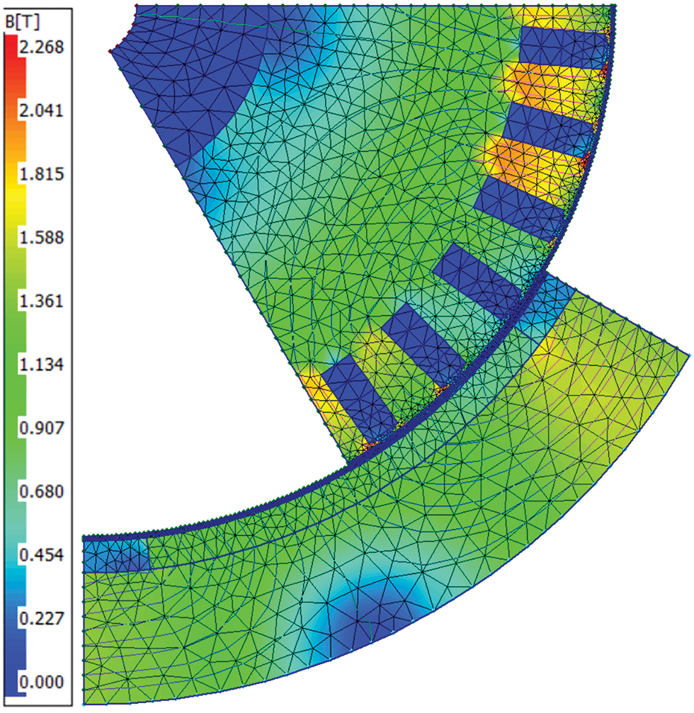
Figure 1: Hub motor 2D finite element simulation diagram
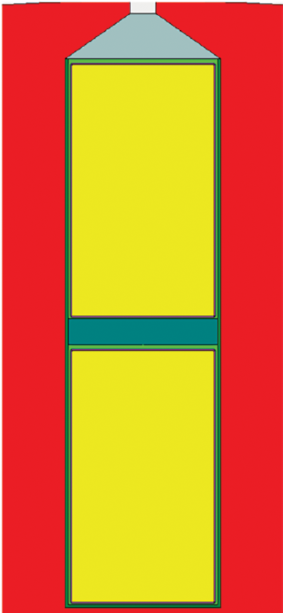
Figure 2: Schematic diagram of hairpin winding structure
2.2 Loss of External Rotor Hub Motor
Compared with conventional permanent magnet synchronous motors, the stator, rotor, and windings of the external rotor hub motor are in different positions, but the heat source generated inside them is the same. Among them, the loss of the motor mainly includes the loss of the iron core, the copper loss of winding, the loss of the permanent magnet eddies current, and mechanical loss. Because the calculation of mechanical losses is complex and their proportion of total losses is very small, mechanical losses of electric motors are not the main subject of research [17].
The loss of the winding is mainly in the process of hub motor operation, the direct current emitted by the vehicle battery after the inverter is converted into alternating current, the loss generated when passing through the motor coil [18]. According to the Joule-Lenz law, the loss is:
where:
The loss of core of the stator and rotor is due to the unavoidable loss caused by the continuous change of the magnetic field of the hub motor during the working process and the continuous cutting of the magnetic inductance lines [19]. The core losses are as follows:
where:
According to the law of magnetic induction, when the external magnetic field changes, the permanent magnet of the hub motor will have an eddy current-like induced electromotive force and current [20]. The eddy current losses are:
where:
When the motor is running stably, there is theoretically no internal change in the magnetic field. However, due to the space harmonics of the magnetomotive force, the time harmonics of the stator current, and the permeability change. This will cause a change in the magnetic flux in the stator, which in turn will produce eddy currents. In addition, permanent magnet materials have a high electrical conductivity, so large eddy current losses occur. While the eddy current losses generated by permanent magnets are not large in the total losses, permanent magnets are usually smaller, which causes a large amount of heat to accumulate in the permanent magnets. Permanent magnets are sensitive to temperature, and when the temperature exceeds a certain value, irreversible demagnetization will occur, causing permanent damage to the motor. In addition, there is an air gap in the stator and rotor, which makes it relatively more difficult to dissipate heat from the permanent magnet [21–23].
Therefore, the study of permanent magnet loss is a non-negligible part of the design of permanent magnet synchronous motors. The eddy current loss of permanent magnets is calculated using the finite element method, the equivalent magnetic circuit method, and the numerical calculation method. The eddy current losses of permanent magnets are calculated by finite element simulation.
According to the basic parameters of the motor in Table 1, the electromagnetic loss model of the hub motor is established by software as shown in Fig. 3, the loss curve of each part of the motor is shown in Fig. 4, and the power loss of each part of the motor is shown in Table 2.
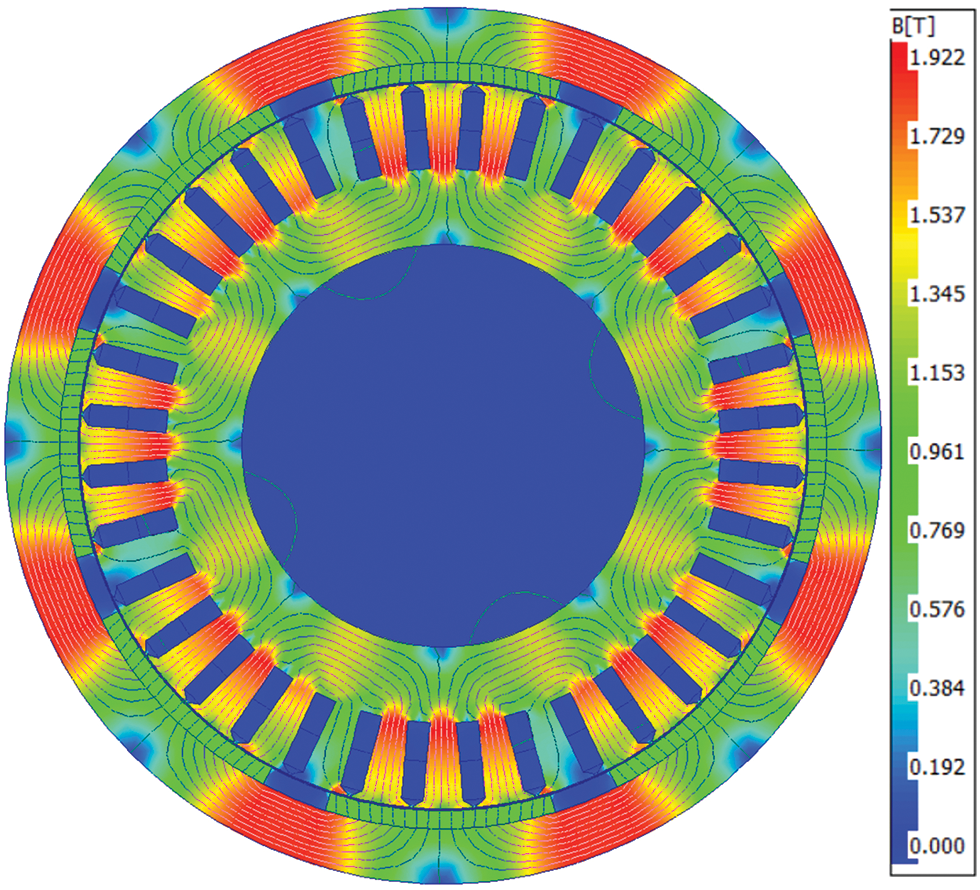
Figure 3: Hub motor electromagnetic loss model
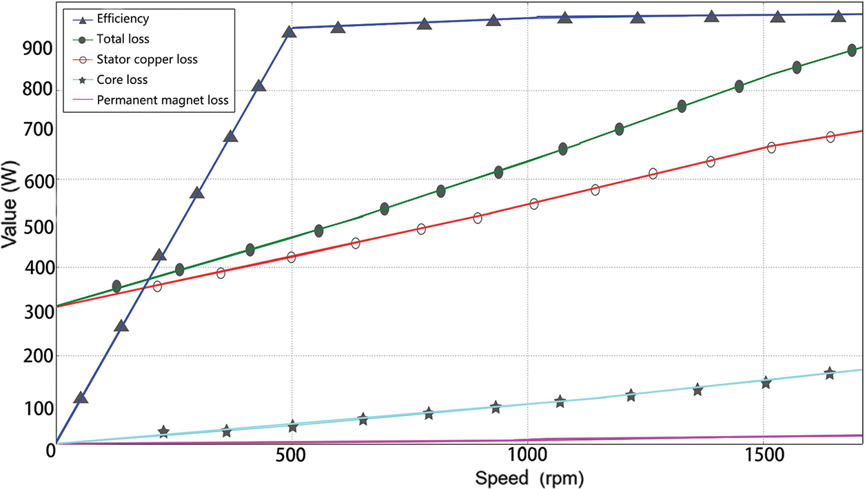
Figure 4: The loss curve for each part of the motor

2.3 Thermal Analysis of the External Rotor Hub Motor
The temperature field distribution of each component of the motor will be affected by the correlation coefficient of the temperature field of the hub motor, so it is necessary to calculate the correlation coefficient of the motor, and the formula is as follows [24]:
The convective heat transfer of the windings is as follows:
where:
The heat dissipation coefficient of the stator is:
where:
The heat dissipation coefficient of the rotor is:
where:
The heat dissipation coefficient of the chassis is:
where:
When the motor is running under rated working conditions, its maximum temperature is mainly concentrated on the lamination and windings of the stator. When cooled with natural air, the maximum temperature can reach 152.91°C. Due to the axial heat transfer of the motor shaft, the temperature rise of the windings and laminations is very high, and the heat dissipation of the stator section is poor, and the temperature from the inside to the outside is gradually reduced. The difference between the minimum and maximum temperature inside the motor is 75°C. The temperature rise of the motor is mainly caused by various losses, and among the losses of the motor, iron loss and copper loss are the main losses of the motor. In the temperature field simulation of a water-cooled motor, the influence of other factors on the calculation results is negligible.
Since the losses of hub motors are difficult to calculate by analytical method, it is necessary to use finite element analysis software of electromagnetic fields to calculate the losses of the motor before analyzing the temperature and flow fields of the motor [25,26].
The simulation software can see the temperature distribution of the stator and motor rotor. The simulated temperature distribution of the stator and rotor is shown in Figs. 5 and 6.
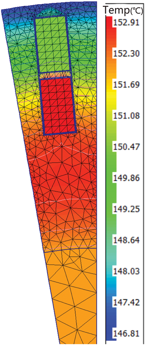
Figure 5: Stator simulation temperature profile
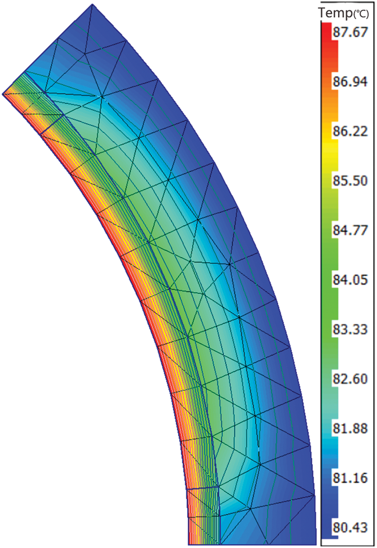
Figure 6: Rotor simulation temperature profile
3 Design and Optimization of the Cooling Structure in the Groove of the Outer Rotor Hub Motor
3.1 Design of Water Cooling in the Tank
In view of the shortcomings of the existing one-way waterway, a new type of double-layer in-tank cooling water jacket was proposed. The cooling channel is divided into two layers, which are arranged at the top and bottom of the winding. Compared with the cooling channel in the single-layer tank, it not only increases the contact area between the winding and the water channel but also makes the internal heat dissipation of the hub motor more uniform. In the whole heat dissipation system, only the diverter valve needs to be introduced to complete the heat dissipation cycle work, so it has strong operability.
In the water cooling mode in the motor tank, when the cooling pipe occupies a large space and the winding occupies a small space, the cooling effect is relatively good [27]; Conversely, the cooling effect will be reduced, but the copper loss will be relatively small. Therefore, the allocation of space in the tank was studied from the perspective of the cooling effect and the change in copper loss. For the oil cooling method in the motor tank, the reasonable allocation of the winding space and the oil cooling pipe space in the motor tank is particularly important for the heat dissipation of the motor. When the cooling oil channel occupies a large space and the winding occupies a small space, the cooling effect is relatively good. However, when the same current is introduced into the winding, the copper loss of the motor will increase. Conversely, the cooling effect will be reduced, but the copper loss will be relatively small. Therefore, the allocation of space in the tank was studied from the perspective of cooling effect and copper loss change. The rectangular cross-section cooling method is used to study the oil-cooled motor tank, and the simplified shape of the single groove of the motor is shown in Fig. 7.
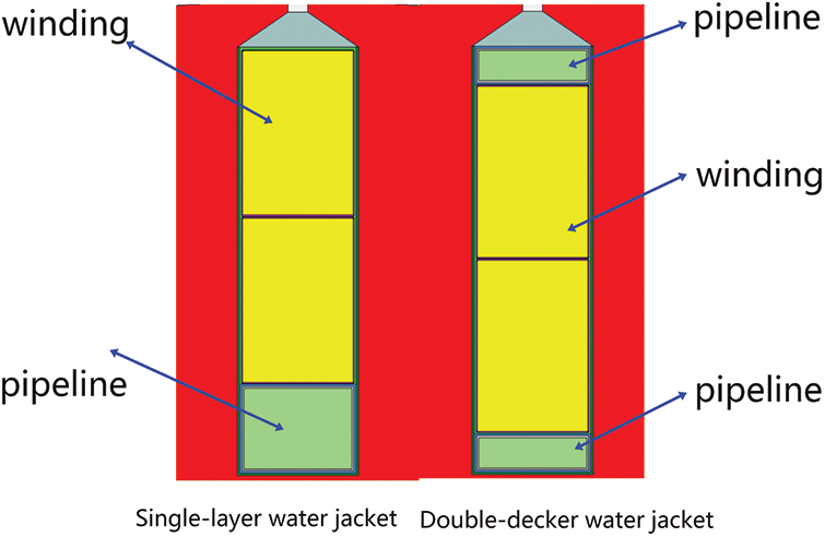
Figure 7: Simplified diagram of a single slot of the motor
3.2 Simulation Analysis of the Design Temperature Field of Water Cooling in the Tank
Because the motor model is too complex, the direct calculation of the full 3D model will occupy more computer resources and time, to study the heat dissipation characteristics of the hub motor itself, the temperature rise inside can be ignored, and the heat transfer model is assumed as follows:
(1) All heat sources inside the motor are equivalent to one total heat source. The heat generated by the motor is dissipated through the cooling structure of the water channel, and a small part is transmitted to the surrounding air by the rotor shell, regardless of radiation heat exchange.
(2) The surface of the motor housing is a smooth and flat cylindrical surface, ignoring the influence of other external structures. Based on the above assumptions, the total loss of the 75 kW permanent magnet synchronous motor is 1558 W as the heat source. It is known that the effective area of the inner wall surface of the water jacket is 0.1973 m3, and the equivalent heat flux q is 23400 W/m2. It is loaded on the inner wall of the water jacket and the contact surface of the stator as a thermodynamic boundary condition.
In order to ensure the accuracy and efficiency of the calculation, high requirements are put forward for the accuracy and scale of the drawing of the model [28]. To solve this problem, the finite element simulation analysis of the professional motor simulation software Motor-CAD was used, and the model adopted the full model solution mode. By discretizing the governing equations in the continuous computational domain, the required discrete equations are obtained.
To accurately calculate the flow and temperature fields of different models, an appropriate meshing strategy is required. In this study, the problem of solving the temperature field and flow field of the permanent magnet synchronous motor in the water-cooled system is discussed. At the fluid-solid interface, the velocity and temperature gradients vary greatly, and to accurately reflect these changes, it is necessary to use enough nodes in the gradient direction. In order to accurately describe the parameters of the boundary layer, a 3D model of the expansive layer boundary mesh was used to divide the fluid domain. The dimensions of the bulk mesh elements are 2 mm and are densely meshed in the boundary layer. The boundary layer consists of 3 layers with a density change rate of 1.2. The meshing is shown in Fig. 8.
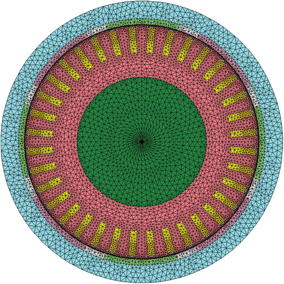
Figure 8: Mesh division diagram of the hub motor
3.3 Comparative Analysis of the Cooling Structure in the Groove of the Outer Rotor Hub Motor
To explore the influence of the double-layer tank water jacket on the heat dissipation effect of each component of the hub motor, this paper will compare and analyze the water jacket with the commonly used single-layer tank water jacket. The waterway structure of the water jacket in the double-layer tank and the water jacket in the single-layer tank adopts the same cross-sectional area and number of rings, where N = 8, the initial temperature of the coolant in the water jacket and the hub motor are set to 40°C, and the inlet flow rate of the coolant is 10 L/min. When the simulation reaches a steady state, the contour diagram of the temperature distribution of the windings, the stator core, and the permanent magnet in the hub motor tank is shown in Fig. 9. As can be seen from Fig. 9, under the same conditions, the heat dissipation capacity of the double-layer tank water jacket is significantly better than that of the commonly used single-layer tank water jacket, and the maximum temperature is reduced by 23.8°C. The maximum temperature is reduced by 37°C compared to natural ventilation cooling. As can be seen in Fig. 10, there is a temperature difference between the upper and lower windings. The heat dissipation conditions of the windings close to the teeth of the stator core are better than those close to the yoke of the stator core. Therefore, the temperature of the winding close to the tooth part of the stator core is low, and the end temperature is higher because the end winding is seriously heated and the heat dissipation conditions are poor. As can be seen in Fig. 11, the overall temperature difference of the permanent magnet is not large. Due to the presence of an air gap, the radial heat dissipation of the permanent magnet is less, and there is a certain amount of convective heat transfer at the end, so the temperature near the stator end is high and the outside temperature is low.
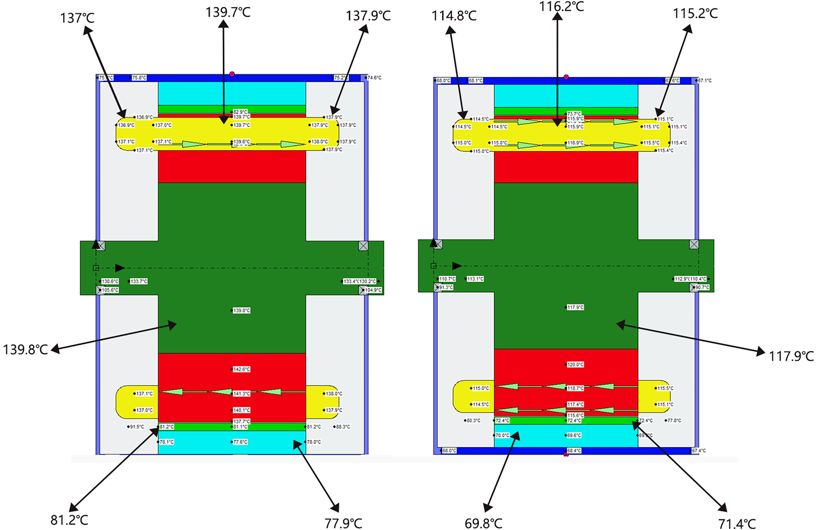
Figure 9: Overall axial temperature distribution of the motor
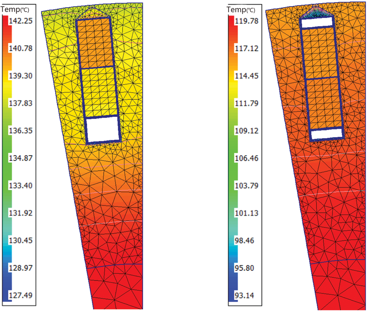
Figure 10: Comparison of stator and winding temperature indexing
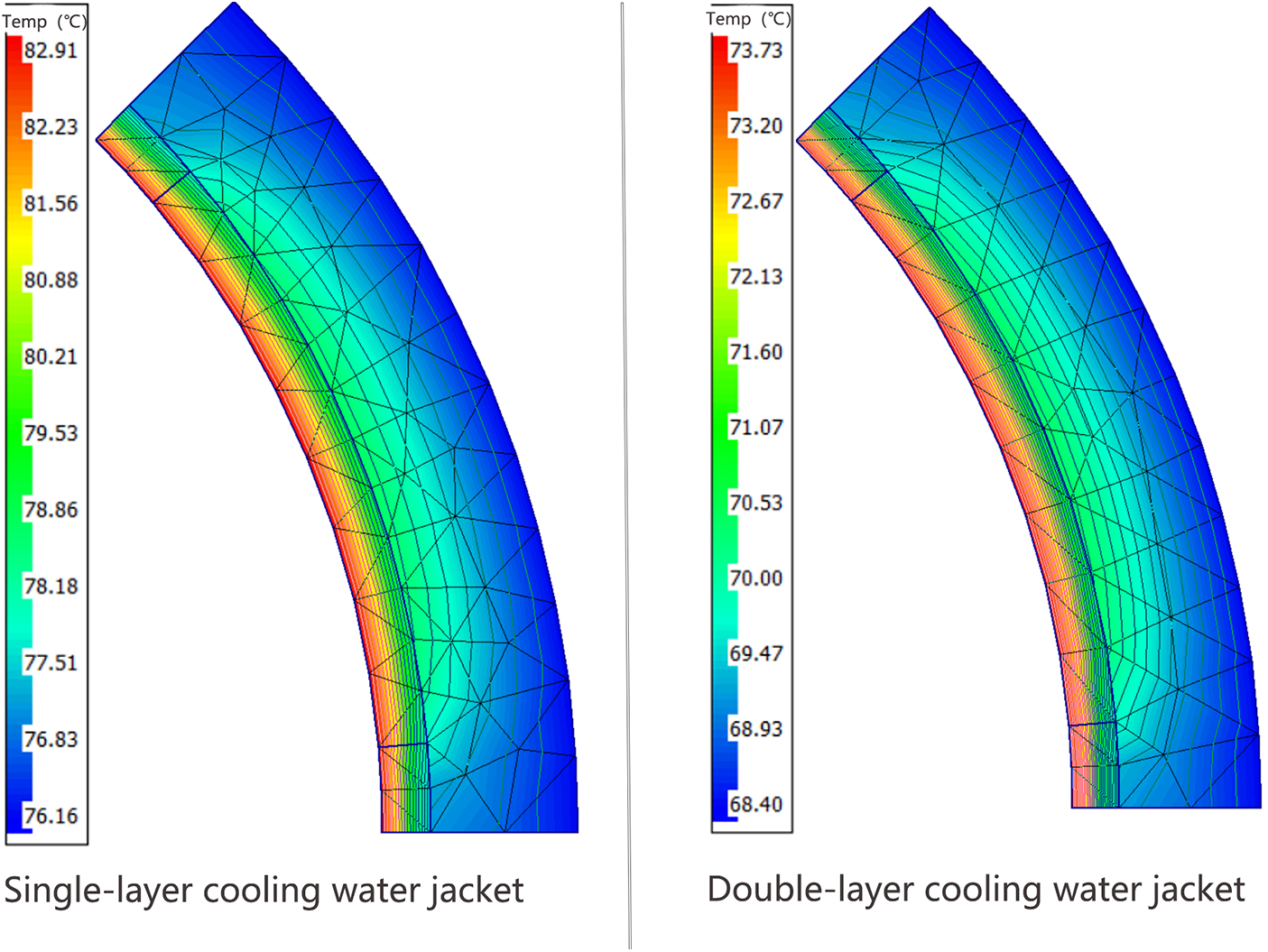
Figure 11: Comparison of rotor and permanent magnet temperature distributions
It can also be seen from the temperature distribution map in Fig. 9 that there is also a certain difference in the heat dissipation uniformity of the two water jackets. In order to facilitate the analysis, the temperature distribution contour of the shaft/diameter section of the hub motor and the temperature variation curve along the shaft were intercepted, as shown in Figs. 12 and 13, respectively.
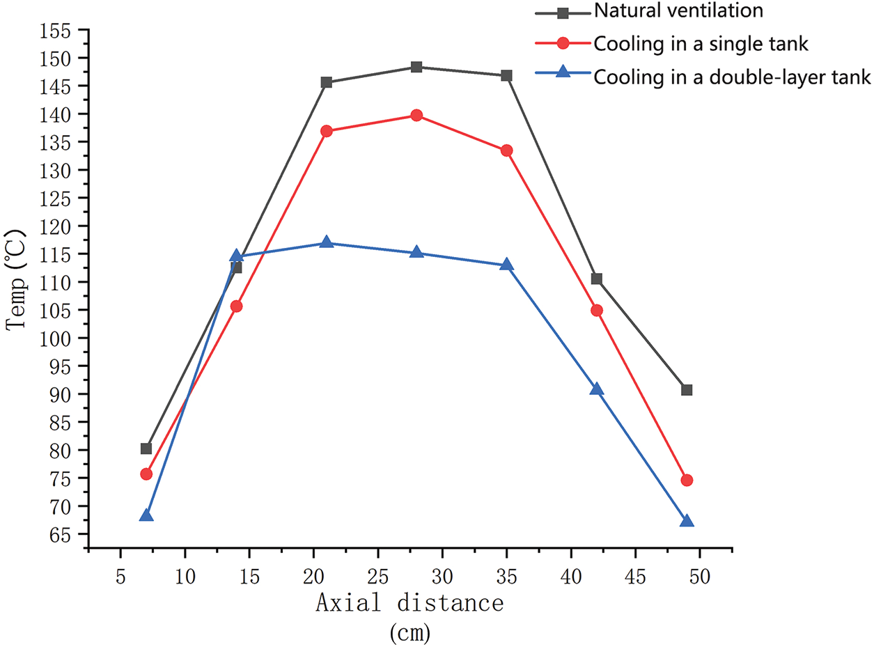
Figure 12: Diagram of the axial temperature distribution of the motor
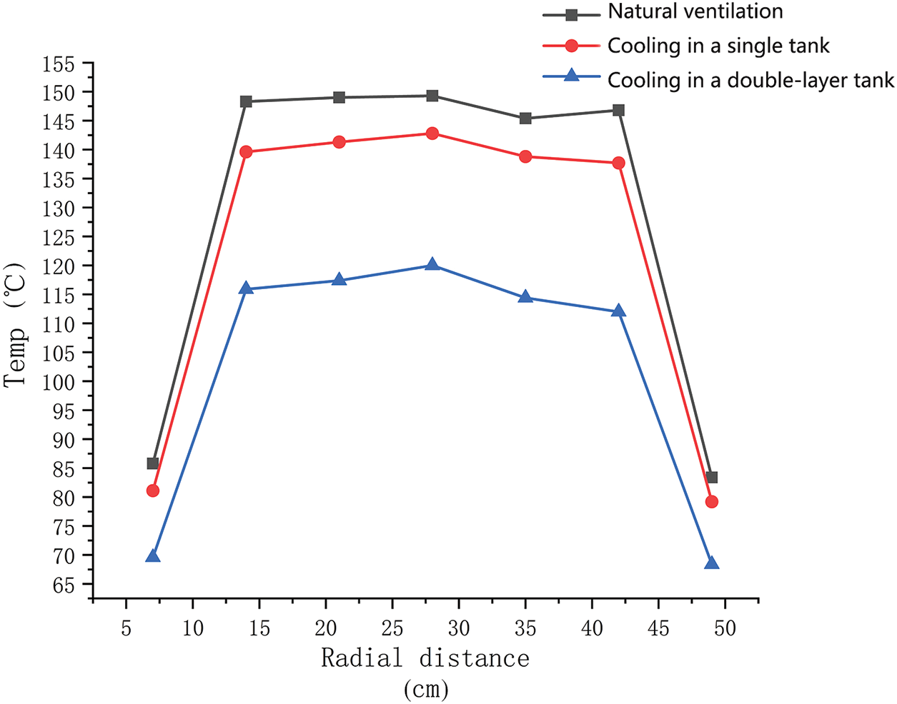
Figure 13: Diagram of the radial temperature distribution of the motor
As can be seen from Fig. 12, the temperature of the motor is inconsistent at the inlet and outlet of the single-layer water jacket. This indicates that the side of the jacket near the inlet dissipates heat better than the side near the outlet. This is due to the absorption of water in the water jacket and the absorption of part of the heat generated by the various components in the hub motor, which gradually increases the water temperature and leads to a decrease in its heat dissipation capacity. From the perspective of heat transfer, because the winding is close to the inner wall of the water jacket, the heat dissipation effect of the water jacket on the winding is better. The end windings accumulate largely, so the temperature gradient along the axial direction of the windings is larger. It can also be seen from Fig. 12 that the temperature distribution of the hub motors of the two water jackets is along the axial direction. On the side of the water inlet, the temperature difference of the motor is only 0.5°C~1°C, while the temperature difference on the side of the water outlet is 4°C~5°C. This shows that the double-layer cooling water jacket can make up for the poor heat dissipation on one side of the outlet of the cooling water jacket in the single-layer tank. On the whole, the heat dissipation effect of the cooling water jacket in the double-layer tank is better than that of the cooling water jacket in the single-layer tank, and the overall cooling effect of the motor is remarkable. Compared to natural ventilation, the maximum temperature was reduced by 33.13°C, and the cooling effect was increased by about 27.7%.
As can be seen from the radial temperature variation diagram in Fig. 13. The overall temperature distribution of the hub motor with a double-layer water jacket is relatively uniform, which is determined by the symmetry of the structure. It can also be seen from Fig. 13 that the temperature difference between the two water jackets along the radial direction gradually increases, and the temperature difference increases from 1°C~2°C close to the water jacket to 7°C~9°C inside, indicating that the cooling water jacket in the double-layer tank has stronger heat dissipation ability for each component inside the hub motor.
To sum up, the double-layer tank cooling water jacket can overcome the problem of poor heat dissipation on one side of the water outlet of the single-layer water jacket, and the overall heat dissipation effect of each component inside the hub motor is better. In order to achieve the optimal cooling effect of the motor, the number of parallel connections of the cooling oil duct in the motor is set to two pipelines in parallel.
4 Effect of Coolant Flow Rate on the Temperature Field
In fluid mechanics, the Reynolds number is used to judge the fluid flow state, and it is generally believed that when the Reynolds number is less than the critical value, the fluid is considered to be a laminar flow state. When the Reynolds number exceeds the critical value, the fluid is considered to be in a turbulent state. When steady flow occurs, the convective heat transfer capacity of the fluid increases, but the corresponding flow resistance increases [29]. For a fixed pipeline, the formula for calculating the fluid Reynolds number is Eq. (8). When the pipe size and fluid parameters are determined, the Reynolds number is proportional to the flow rate. Therefore, for cooling pipes, the coolant flow rate is determined.
where:
Fig. 14 shows the average temperature curve of the motor end windings with different flow rates of coolant.
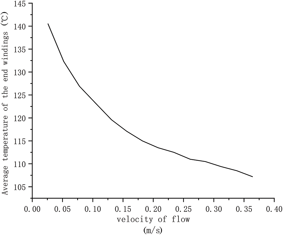
Figure 14: Temperature curves of the end windings under different flow rates
In actual engineering operation, due to the high speed of coolant injection, not only is the mechanical strength of the motor casing required, but also the water pump power will be consumed in the process of injecting coolant, which is not conducive to energy savings. When the flow rate of the coolant injection reaches a certain value, the cooling effect of the motor is not obvious by continuing to increase the coolant flow [30–32], Considering the factors such as energy saving and cooling effect, the inlet flow rate range of 0.20–0.25 m/s for the injection of coolant was selected as the optimal flow rate selection area for this water jacket.
(1) A new type of heat dissipation structure of a double-layer cooling water jacket in the tank is proposed, which has a better heat dissipation effect on each component of the hub motor than the natural ventilation cooling method. In particular, the heat dissipation effect on the stator core and winding is more obvious, and it has the advantage of uniform axial heat dissipation, which overcomes the problem of narrow internal space and serious heat accumulation of single-hub motors. After simulation analysis and comparison, the overall cooling effect is increased by 27.7% under the same working conditions.
(2) The paper studies the coolant flow rate and finds that when the flow rate range is 0.20–0.25 m/s, the temperature rise curve of the motor shows a significant change. Before this range, the temperature rise curve changes significantly; After that, the temperature rise changed relatively slowly, and it basically reached a saturation state. Therefore, the flow rate range of 0.20–0.25 m/s is a more economical choice.
(3) In this paper, the electromagnetic, loss and temperature fields of the 75 kW external rotor hub motor are studied in order to solve the key problems such as difficult heat dissipation and over-limit temperature rise. The conclusions obtained are of guiding significance for suppressing the temperature rise of key components of hub motors and for the safe and stable operation of hub motors under the corresponding temperature limits. Subsequently, the method of combining control and ontology can be used to study the dynamic temperature rise of the hub motor under the actual operating road conditions.
Acknowledgement: The authors extend their sincere gratitude to the team. Without their assistance and encouragement, this research would not have been completed.
Funding Statement: This work is supported by National Science Foundation of China (Grant No. 51705306).
Author Contributions: The authors confirm their contribution to the paper as follows: study conception and design: Zhuo Liu, Yecui Yan; data collection: Zhuo Liu; analysis and interpretation of results: Zhuo Liu, Yecui Yan; draft manuscript preparation: Zhuo Liu. All authors reviewed the results and approved the final version of the manuscript.
Availability of Data and Materials: The data utilized in this study are derived from experiments conducted as part of the research project. Readers can request the dataset by contacting us through the provided email address. Due to confidentiality agreements and ethical considerations, certain data may be restricted, and thus, unavailable data cannot be disclosed.
Ethics Approval: Not applicable.
Conflicts of Interest: The authors declare that they have no conflicts of interest to report regarding the present study.
References
1. Carl J, Fedor D. Tracking global carbon revenues: a survey of carbon taxes versus cap-and-trade in the real world. Energy Policy. 2016;96:50–77. [Google Scholar]
2. Lamb WF, Wiedmann T, Pongratz J, Robbie A, Monica C, Jos GJO, et al. A review of trends and drivers of greenhouse gas emissions by sector from 1990 to 2018. Environ Res Lett. 2021;16:073005. [Google Scholar]
3. Jian L. Research status and development prospect of electric vehicles based on hub motor. In: 2018 China International Conference on Electricity Distribution (CICED), 2018; Tianjin, China: IEEE; p. 126–9. [Google Scholar]
4. Kazak AN, Filippov DM. Development of in-wheel motor for vehicles. In: 2019 IEEE Conference of Russian Young Researchers in Electrical and Electronic Engineering (EIConRus), 2019; Saint Petersburg and Moscow, Russia: IEEE; p. 1406–8. [Google Scholar]
5. Aloeyi EF, Ali N, Wang Q. A review of in-wheel motors for electric vehicle propulsion. In: 2022 IEEE Transportation Electrification Conference and Expo, Asia-Pacific (ITEC Asia-Pacific), 2022; Haining, China: IEEE; p. 1–6. [Google Scholar]
6. Luque D, Ruppert E, Bianch N, Castiello M. Analysis of a three-phase in-wheel electric motor. In: 2009 44th International Universities Power Engineering Conference (UPEC), 2009; Glasgow, UK: IEEE; p. 1–4. [Google Scholar]
7. Leng S, Jin L. Numerical simulation of heat dissipation of surface mounted permanent magnet synchronous hub motor. Therm Sci. 2021;25:4059–66. [Google Scholar]
8. Chawrasia SK, Das A, Kumar Chanda C. Design and analysis of electric bike hub-motor using motor-CAD. In: 2020 3rd International Conference on Energy, Power and Environment: Towards Clean Energy Technologies, 2020; Shillong, Meghalaya, India: IEEE; p. 1–6. [Google Scholar]
9. Jiang C, Zhao L, Du X, Yang Z. Heat dissipation analysis of electric vehicle in-wheel motor based on vehicle working conditions. China Mechanical Eng. 2016;27:1839–45 (In Chinese). [Google Scholar]
10. Wang X, Du J. CFD analysis of the heat dissipation characteristics of the spiral cooling circuit of the automotive motor. Trans Chin Electrotech Society. 2018;33:955–63 (In Chinese). [Google Scholar]
11. Zhao L, Jiang C, Xu X, Yang Z. Effect of oil cooling on temperature characteristics of external rotor hub motor under vehicle operating environment. Automotive Eng. 2019;41:373–80 (In Chinese). [Google Scholar]
12. Ye Z, Luo W, Zhang W, Feng Z. Simulative analysis of traction motor cooling system based on CFD. In: 2011 International Conference on Electric Information and Control Engineering, 2011; Wuhan, China: IEEE; p. 746–9. [Google Scholar]
13. Wang M, Chen Z. Research on permanent magnet structure of permanent magnet synchronous motor for electric vehicle. In: 2022 2nd International Conference on Electrical Engineering and Control Science (IC2ECS), 2022; Nanjing, China: IEEE; p. 990–3. [Google Scholar]
14. Xue S, Michon M, Popescu M, Mircea P, Giuseppe V. Optimisation of hairpin winding in electric traction motor applications. In: 2021 IEEE International Electric Machines & Drives Conference (IEMDC), 2021; p. 1–7. [Google Scholar]
15. Berardi G, Nategh S, Bianchi N, Nicola B, Yves T. A comparison between random and hairpin winding in E-mobility applications. In: IECON 2020–The 46th Annual Conference of the IEEE Industrial Electronics Society, 2020; Singapore, Singapore: IEEE; p. 815–20. [Google Scholar]
16. Arzillo A, Braglia P, Nuzzo S, Barater D, Franceschini G, Gerada D, et al. Challenges and future opportunities of hairpin technologies. In: 2020 IEEE 29th International Symposium on Industrial Electronics (ISIE), 2020; Delft, Netherlands: IEEE; p. 277–82. [Google Scholar]
17. Chen Q, Yang X. Calculation analysis of thermal loss and temperature field of in-wheel motor in micro-electric vehicle. J Mech Sci Technol. 2014;28(8):3189–95. doi:10.1007/s12206-014-0728-8. [Google Scholar] [CrossRef]
18. Magnussen F, Sadarangani C. Winding factors and Joule losses of permanent magnet machines with concentrated windings. In: IEEE International Electric Machines and Drives Conference, 2003. IEMDC’03, 2014; Madison, WI, USA: IEEE; p. 333–9. [Google Scholar]
19. Sun YL, Zhang SW, Chen G, Tang Y, Liang FY. Experimental and numerical investigation on a novel heat pipe-based cooling strategy for permanent magnet synchronous motors. Appl Therm Eng. 2020;170:114970. doi:10.1016/j.applthermaleng.2020.114970. [Google Scholar] [CrossRef]
20. Zhu S, Cheng M, Dong JN, Du J. Core loss analysis and calculation of stator permanent-magnet machine considering DC-biased magnetic induction. IEEE Trans Ind Electron. 2014;61(10):5203–12. doi:10.1109/TIE.2014.2300062. [Google Scholar] [CrossRef]
21. Deak C, Petrovic L, Binder A, Mirzaei M, Irimie D, Funieru B. Calculation of eddy current losses in permanent magnets of synchronous machines. In: 2008 International Symposium on Power Electronics, Electrical Drives, Automation and Motion, 2008; Ischia, Italy: IEEE; p. 26–31. [Google Scholar]
22. Li ZX, Yang GL, Fan YM, Li JH. Irreversible demagnetization mechanism of permanent magnets during electromagnetic buffering. Def Technol. 2021;17(3):763–74. doi:10.1016/j.dt.2020.05.005. [Google Scholar] [CrossRef]
23. Baranski M, Szelag W, Lyskawinski W. Experimental and simulation studies of partial demagnetization process of permanent magnets in electric motors. IEEE Trans Energy Convers. 2021;36(4):3137–45. doi:10.1109/TEC.2021.3082903. [Google Scholar] [CrossRef]
24. Zhou Z, Yang W, Li Z, Li H. Comparative analysis of temperature rise of in-wheel motor based on water-cooled cooling method. J Chongqing Univ Technol (Nat Sci). 2021;35:63–72+208 (In Chinese). [Google Scholar]
25. Staton DA, Cavagnino A. Convection heat transfer and flow calculations suitable for electric machines thermal models. IEEE Trans Ind Electron. 2008;55(10):3509–16. doi:10.1109/TIE.2008.922604. [Google Scholar] [CrossRef]
26. Zhao N, Liu W. Loss calculation and thermal analysis of surface-mounted PM motor and interior PM motor. IEEE Trans Magn. 2015;51:1–4. doi:10.1109/INTMAG.2015.7157405. [Google Scholar] [CrossRef]
27. Malekzadeh A, Heydarinasab A, Jahangiri M. Magnetic field effect on laminar heat transfer in a pipe for thermal entry region. J Mech Sci Technol. 2011;25(4):877–84. doi:10.1007/s12206-011-0140-6. [Google Scholar] [CrossRef]
28. Xu Y, Xu Z, Wang H, Liu W. Research on magnetic-fluid-thermal-stress multi-field bidirectional coupling of high-speed permanent magnet synchronous motors. Case Stud Therm Eng. 2024;54(6):104012. doi:10.1016/j.csite.2024.104012. [Google Scholar] [CrossRef]
29. Wei T, Willmarth WW. Reynolds-number effects on the structure of a turbulent channel flow. J Fluid Mech. 1989;204:57–95. doi:10.1017/S0022112089001667. [Google Scholar] [CrossRef]
30. Tao DJ, Pan B, Ge B, Wang LK. Cooling analysis of vehicle hub motor temperature field. In: 2019 22nd International Conference on Electrical Machines and Systems (ICEMS), 2019; Harbin, China: IEEE; p. 1–6. [Google Scholar]
31. Yang S, Lee M, Kim JH, Insoung J, Sehyun R, Daekwang K. Numerical & experimental investigation on the cooling performance affected by the flow rate of coolant of the inverter integrated WFSM. In: 2018 21st International Conference on Electrical Machines and Systems (ICEMS), 2018; Jeju, Republic of Korea: IEEE; p. 2510–3. [Google Scholar]
32. Lei X, Wang Y, Deng Y, Su C, Lin X, Chen G. Combined numerical and experimental investigation on the optimum coolant flow rate for automotive thermoelectric generators. J Electron Mater. 2019;48(4):1981–90. doi:10.1007/s11664-018-06879-9. [Google Scholar] [CrossRef]
Cite This Article
 Copyright © 2024 The Author(s). Published by Tech Science Press.
This work is licensed under a Creative Commons Attribution 4.0 International License , which permits unrestricted use, distribution, and reproduction in any medium, provided the original work is properly cited.


 Submit a Paper
 Propose a Special lssue
 View Full Text
 Download PDF
 Downloads
 Citation Tools