 Open Access
ARTICLE
Numerical Simulation of Liquified Natural Gas Boiling Heat Transfer Characteristics in Helically Coiled Tube-in-Tube Heat Exchangers
School of Mechanical and Electronic Engineering, Shandong Jianzhu University, Jinan, 250101, China
* Corresponding Author: Fayi Yan. Email:
(This article belongs to the Special Issue: Two-phase flow heat and mass transfer in advanced energy systems)
Frontiers in Heat and Mass Transfer 2024, 22(5), 1493-1514. https://doi.org/10.32604/fhmt.2024.055324
Received 23 June 2024; Accepted 28 August 2024; Issue published 30 October 2024
Abstract
Helically coiled tube-in-tube (HCTT) heat exchangers are widely applied to the process technology because of their compactness and higher heat transfer efficiency. HCTT heat exchangers play an important role in liquified natural gas (LNG) use and cold energy recovery. The heat transfer characteristics, pressure distribution, and degree of vaporization of LNG in HCTT heat exchangers are numerically investigated. By comparing the simulation results of the computational model with existing experimental results, the effectiveness of the computational model is verified. The numerical simulation results show the vapor volume fraction of the HCTT heat exchanger is related to the inlet Reynolds number, inner tube diameters, and helix diameter. The vapor volume fraction increases rapidly from the fourth to the seventh equal division points of the helix tube length. On condition that the inlet Reynolds number is greater than 33500, the pressure drop rate gradually increases. When the magnitude of the vapor volume fraction is below 0.2, the heat transfer coefficient increase rate is greater than that when the vapor volume fraction is above 0.2. The heat exchange efficiency of HCTT heat exchangers increases with the decrease of the ratio of helix diameter to inner tube diameter.Keywords
Nomenclature
| C | Specific heat capacity, J/(kg.K) |
| d | Tube diameter, mm |
| D | Helix diameter of helix tube, mm |
| F | Force, N |
| G | Mass flow, kg/(m2.s) |
| i | Enthalpy, J |
| k | Turbulent kinetic energy |
| Ratio of the thermal conductivity between the liquid phase to the vapor phase | |
| L | Helix tube pitch, mm |
| n | Helix tube turns |
| P | Pressure, MPa |
| q | Heat flux, kW/m2 |
| r | Latent heat of vaporization, kJ/kg |
| Source term | |
| T | Temperature, oC |
| v | Velocity, m/s |
| V | Volume, m3 |
| x | Vapor quality |
| Martinelli number | |
| Greek Symbols | |
| α | Volume fraction |
| ε | Turbulent energy dissipation rate |
| λ | Thermal conductivity, W/(m.K) |
| ρ | Density, kg/m3 |
| Stress strain tensor, MPa | |
| Subscripts | |
| i | Inner |
| o | Outer |
| q | Primary phase |
| p | Secondary phase |
| l | Liquid phase |
| m | Mixture phase |
| CB | Convective boiling |
| Eq | Equivalent |
| Dimensionless Number | |
| Re | Reynolds number |
| Nu | Nusselt number |
| Pr | Prandtl number |
| Dn | Dean number |
| Bo | Boiling number |
| Abbreviation | |
| HCTT | Helically coiled tube-in-tube heat exchanger |
| LNG | Liquefied natural gas |
| PCM | Phase-changing material |
| RANS | Randomized algorithm with non-uniform sampling |
| SIMPLEC | Semi-implicit method for pressure-linked equations with corrected convergence |
Liquefied natural gas is a kind of clean energy which is mainly composed of methane. The cold energy generated during the vaporization of liquified natural gas (LNG) can be recovered through a heat exchanger. Compared with straight tube heat exchangers, helically coiled tube-in-tube (HCTT) heat exchangers have a compact structure and can generate secondary flow through centrifugal force to improve heat exchange efficiency so that it can meet the requirements of cold energy recovery [1] during the vaporization of LNG.
Helically coiled heat exchangers can generate the secondary flow from the helix structure which can damage the boundary of the heat transfer layer. Generally, the spiral bellows structure and the spiral fin structure are used to increase the heat exchange efficiency of the HCTT heat exchanger [2,3]. Besides, Pethkool et al. [4] investigated the influences of the helically corrugated tube geometric parameters on the heat exchange enhancement. The results show that the increase of the heat exchange efficiency is above 123% compared to the smooth straight tube heat exchanger. Zhang et al. [5] explored the flow in heat transfer helically coiled tubes and found that the spherical corrugation structure improves the heat transfer efficiency by 1.05~1.7 times. Fouda et al. [6] calculated the heat exchange efficiency of multi-tube HCTT heat exchangers and concluded that the internal tube increased heat transfer efficiency. Liu et al. [7] developed a technique for regenerating cooling air for aircraft engines by using a dual cold source HCTT heat exchanger. Kirkara et al. [8] investigated heat exchange enhancement technologies by combining the helically coiled tube and corrugated surface. The results show that this structure can form vortices and secondary flows, thereby achieving higher heat transfer efficiency. Mahdi et al. [9] investigated the potential of improving the energy storage and recovery performance of the helical coiled tube and shell phase change material (PCM) based storage systems. Wang et al. [10] explored the thermal enhancement in an HCTT heat exchanger and found that the thermal enhancement factor reached a maximum value of 1.28. Cao et al. [11] studied the flow condensation of R134a inside an HCTT heat exchanger. The study results show that some special parameters would result in higher entropy generation.
The boiling flow heat exchange process in HCTT heat exchangers has two parts: the convection heat exchange and boiling heat exchange. Wu et al. [12] studied the calculation method of two-phase boiling flow and heat transfer in helical tubes and obtained a calculation model with good predictive ability. Liang et al. [13] simulated the boiling heat transfer in helical tubes with the utilization of deep learning and obtained the computational model. The boiling heat transfer mechanism of helical tubes was investigated by experimental measures [14]. From the experimental results, the obtained boiling heat transfer coefficient is greatly affected by tube pitches. A numerical simulation study was conducted on boiling heat transfer of two-phase flow inside a helical tube [15]. Compared with the corrected “Chen correlation” [16], the average absolute error is very small. Moradkhani et al. [17] used traditional and machine learning techniques to predict the characteristics of the boiling heat transfer in smooth helix tubes, and the average relative error is only 5.93%. Xiao et al. [18] investigated the boiling heat transfer characteristics in helix tubes according to experiments. Wu et al. [19] studied the boiling heat transfer characteristics of two-phase secondary flow in a helix tube. It is indicated that enhancement mechanism of secondary flow in heat transfer at different boiling states. Chen et al. [20] carried out the numerical simulation on acoustic performances of the flow boiling in helix tubes. The study of the heat exchange progress of subcooled flow boiling in helix heat exchangers was carried out by numerical study [21]. Cui et al. [22] investigated the boiling flow of R134a in helix tubes. It is indicated that the mass flow has a more obvious influence on heat transfer coefficients with high vapor quality. Chen et al. [16] experimentally studied the subcooled nucleate boiling in spiral coils with different geometrical dimensions. The results show that the main factors affecting the onset of subcooled nucleate boiling are the heat flux and system pressure. Wongwises et al. [23] investigated the characteristics of the pressure drop and heat transfer in HCTT heat exchangers by experiment. The results show that the heat transfer coefficient was influenced by mass flow.
The above studies on the boiling flow characteristics in HCTT heat exchangers are mostly focused on water, R134a, R601, and other traditional working fluids [24–27]. Salehin et al. [28] and Mustakim et al. [29] studied the characteristics of heat exchange of nanofluids in helically featured straight Pipe and semicircular corrugated Pipe and obtained some meaningful research results. However, there is little few researches on boiling heat transfer by utilizing LNG as the working fluid. The numerical simulation method is used to study the characteristics of the inlet Reynolds number Re and the helix tube geometric parameters on vaporization, heat transfer efficiency, and pressure distribution.
Although extensive research has been carried out on the heat exchange phenomenon of the helix tubes, the existing results are not universally applicable due to the influence of working fluids, tube types, and experimental environments, and cannot be widely applied to helical tube heat exchangers. Especially, the research on the heat and mass transfer mechanism and dynamic behavior characteristics of the vapor-liquid interface during the boiling heat transfer in HCTT heat exchangers is not deep enough. The boiling heat transfer is a common phenomenon in helix tubes, but there are few reports on the research of boiling heat transfer in helical tubes. Therefore, this article studies the influences of the helical tube structure on LNG flow and heat transfer, and obtains the flow and boiling heat exchange characteristics, providing references for the design of HCTT heat exchangers.
As shown in Fig. 1, the HCTT heat exchanger consists of an internal tube and an external tube, which are coaxially installed together and bent into a spiral shape. The heat exchange includes two parts: LNG flows in the internal tube (called inner tube), refrigerant ethylene glycol flows in the external tube (called the outer tube). To achieve the maximum average temperature difference, the flow of the cold and hot fluids in the HCTT heat exchanger is arranged in a convective form, and the outer wall is insulated during the calculation process. The parameters of the HCTT heat exchanger include the inner tube diameter di, the outer tube diameter do, the helix diameter of helix tube D, the helix tube pitch L, and the helix tube turns n. The inner tube wall is made of copper with a thickness of 1mm, and the outer tube wall is cold-rolled carbon steel with a thickness of 1.5 mm.
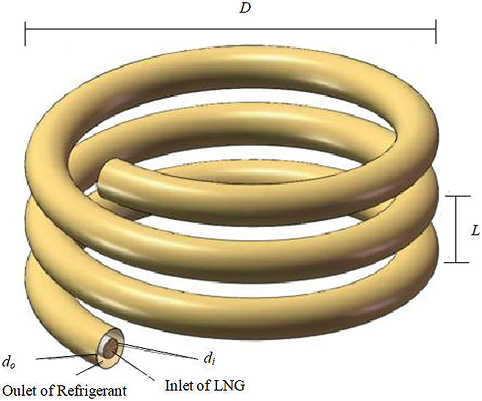
Figure 1: Structure of the HCTT heat exchanger
In numerical calculations of the two-phase flow, the space occupied by each phase is represented by volume fraction
where
The continuity equation, momentum equation, and energy equation related to two-phase flow can be described as the following equations:
The continuous equation of two-phase flow is expressed as Eq. (2).
In Eq. (2),
Momentum equation of two-phase flow is expressed as Eq. (3).
In Eq. (3),
Energy equation of two-phase flow is expressed as follows:
where
The boiling heat transfer numerical simulation adopts the wall boiling heat transfer model based on the Euler model. This model is amended according to the nucleate boiling model of Kurual et al. [27] and Lavieville et al. [30]. The heat flux
where
The k-ε model is based on the Reynolds average Navier-Stokes (randomized algorithm with non-uniform sampling, RANS) equation which uses the turbulent kinetic energy k and the turbulent energy dissipation rate ε to describe turbulence, so the changing process of the turbulence and predict the flow state of bending and rotation can be described.
The governing equation of turbulence energy k is expressed as Eq. (6).
The governing equation of turbulent energy dissipation rate ε is expressed as Eq. (7).
where
LNG is natural gas that is compressed and cooled to its boiling point temperature before becoming a liquid. Generally, LNG is stored under the conditions of 0.4~1.0 MPa and 90~111 K. The physical properties of LNG are basically the same as those of methane, so methane’s physical properties are used instead of LNG in numerical calculations. In the HCTT heat exchanger, LNG flows in the inner tube, and the system pressure is 0.5 MPa, and the inlet temperature of LNG is 110 K. The hydraulic diameter of LNG turbulent flow is set to di. The intensity of turbulence is calculated based on the Re.
Ethylene glycol is a colorless, slightly viscous liquid that can be mixed with water in any proportion. After mixing water with ethylene glycol, the vapor pressure of the cooling water is altered. Therefore, the freezing point of ethylene glycol aqueous solution significantly decreases. The specific heat capacity of ethylene glycol is 3.78 kJ/(kg·°C), and the thermal conductivity is 0.5 W/(m·K), which can meet the heat transfer requirements. Ethylene glycol aqueous solution has stable chemical properties, uniform density, low volatility, and evaporation rate. Therefore, the refrigerant used in this study is ethylene glycol aqueous solution.
The working fluid of the outer tube is ethylene glycol whose inlet temperature is 273.15 K, and the inlet velocity magnitude is 0.5 m/s.
2.4 Grids and Independence Verification
The numerical calculation adopts the finite volume method, and the mesh adopts the hexahedral mesh for the inner tube and the tetrahedral mesh for the outer tube. The grid of the coaxial sleeve heat exchanger is refined by adding a boundary layer near the wall of the heat exchange tube, which can be seen in Fig. 2. In the calculation setting, different numbers of grids are used for grid independence verification to ensure cost savings without affecting the accuracy of numerical solutions. The temperature changes at the inlet and the outlet of LNG flow were used as the basis for measuring grid independence, and the range of temperature changes was verified for grid numbers 286,740, 492,914, 637,212, 798,656, and 949,845, respectively. The results can be seen in Fig. 2. According to Fig. 3 when the number of grids is 798,656, the temperature changes at the inlet and outlet are not significantly different from those at 637,212 grids. As the number of grids increases to 949,845, the temperature change remains basically unchanged. The number of these elements is enough to obtain accurate simulation results, which can be considered grid independent.
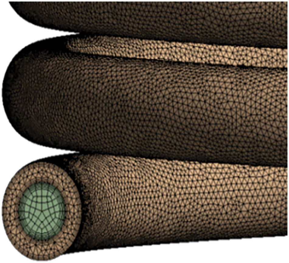
Figure 2: Calculation grids of helix tube
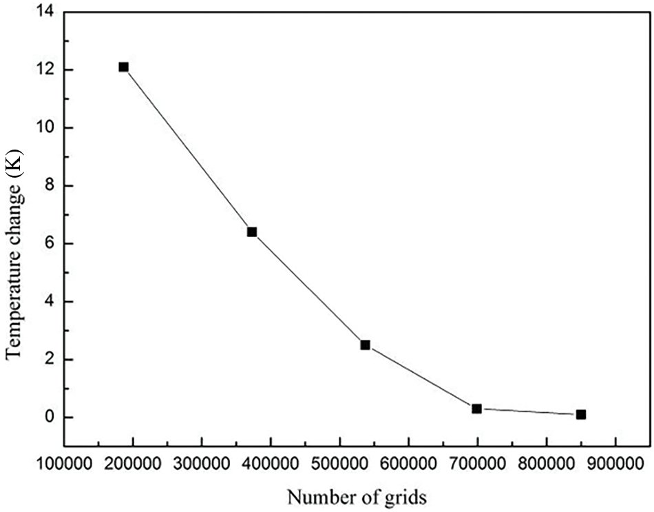
Figure 3: Grid independent verification
Due to the material of the inner tube being copper and having a wall thickness of only 1 mm, the thermal resistance can be ignored. The outer tube wall is insulated. The computational domain of this study is the LNG in the inner tube and the ethylene glycol aqueous solution in the outer tube. Therefore, when conducting calculations in the HCTT heat exchanger, and the calculation domain is the coaxial helical region of the two working fluids.
2.5 Comparison and Verification of Numerical Calculation Result and Existing Experimental Results
The physical model and the same boundary conditions of Chen et al.’s [16] boiling flow experiment are applied to verify the reliability of the numerical calculation model. The geometric parameters and boundary condition data in the experiment are shown in Table 1. In the verified experiment, thermocouples were uniformly arranged along the circumference of each temperature measurement section to measure the temperature of the outer tube wall and the distance between adjacent temperature measurement points of the helix coil is 300 mm. Four N-type thermocouples were evenly installed on the circumference of 0°, 90°, 180°, and 270° on each temperature measurement section. The extraction of temperature around the wall is measured by thermocouples. Therefore, as shown in Fig. 4, in the verification calculation process, the temperature calculation results at 0°, 90°, 180°, and 270° of the same position section were selected as the reference physical quantities. Water was used as the working medium. The comparison of experimental results and the simulation results can be seen from Fig. 5, in which the solid line are the experimental results and the dashed line are the simulation calculation results.

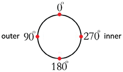
Figure 4: Position in the helix tube
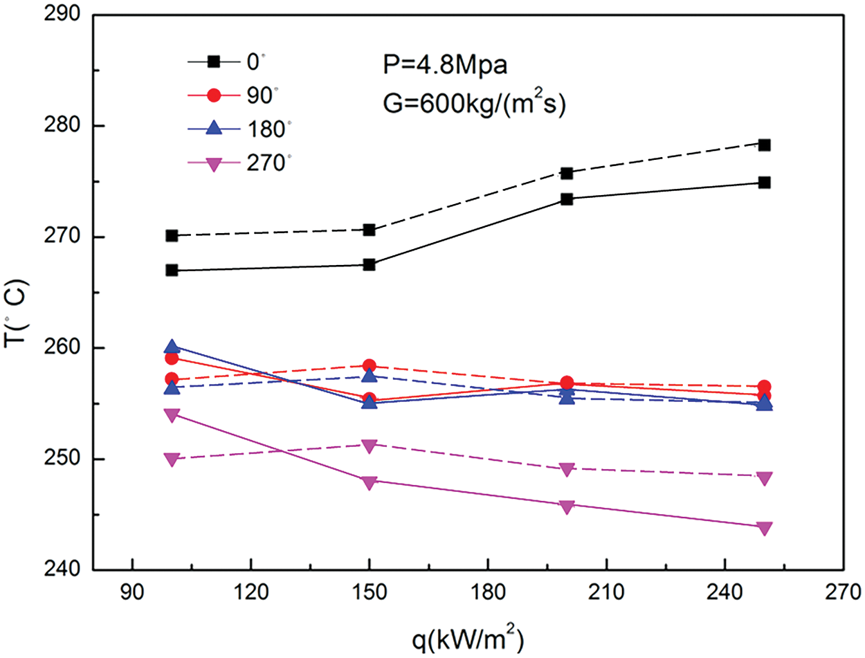
Figure 5: Comparison of experimental and calculation values
It can be seen from Fig. 5 that the distribution trend of numerical calculation results is similar to that of experimental results. The distribution trend of the calculated results on the wall of the inner tube is basically consistent with the experimental results, while the calculation values are slightly larger than the experimental values. The maximum deviation between the numerical calculation values and the experimental values of the inner tube wall temperature is 4.41%. The tube wall temperatures at positions 0°, 90°, and 180° in the experimental results show a slight decrease in fluctuation as the heat flux density increases. The numerical calculation results are a litter higher than the experimental values overall, and the temperature changes trend tend to be stable. The average deviation of the maximum temperature at the positions of 0°, 90°, and 180° is 2.75%. Although the overall trend of the calculated results differs slightly from the experimental results, the average deviation is still less than 10%. This indicates a high degree of fit between the numerical calculation values and the experimental values. Consequently, the selected calculation model is suitable for the numerical calculation of boiling heat transfer for the HCTT heat exchangers.
Regarding selecting the calculation mode, the second-order upwind is used as the discretization criterion, and the SIMPLEC algorithm is selected as the iterative algorithm to ensure the calculation accuracy. To improve the accuracy of the converged results, the calculation residual is set to 1e-5.
Under the condition of D = 200 mm, L = 30 mm, and di = 15 mm, variations of the LNG vapor volume fraction distribution, pressure distribution, and heat transfer efficiency in HCTT heat exchangers are calculated at the Re range of 13500~53500. The distributions of the LNG vapor volume fraction in the helix tube can be seen from Fig. 6, from which the results are similar to the results obtained by the experiment of Murai et al. [31].

Figure 6: Distributions of vapor volume fraction in helix tube under different Re
The liquid phase density is greater than that of the vapor phase, therefore gravity makes the liquid phase of LNG deposits. The upper part of the LNG in the helix tube begins to vaporize, and the liquid phase of LNG is near the outside wall of the helix tube. Meanwhile, the LNG flow is affected by the secondary flow generated from the helix tube. Therefore, the liquid phase of LNG is more affected by the centrifugal force and gravity during flow. The velocity difference between the vapor and liquid phases near the helix tube wall becomes larger, so the lifting forces of the bubbles increase and the upward movements of the bubbles are strengthened.
Fig. 7 shows the vapor volume fraction changes with the helix tube length under different Re. The equal division points of the helix tube length on the abscissa in Fig. 7 represent nodes that divide the helix tube length into 12 equal parts. The vapor volume fraction increases slowly close to the initial equal division points of the helix tube length. As the flow progresses, the growth rate of the vapor volume fraction is the highest at the 5th to 7th equal division point of helix the tube length, and the degree of vaporization is the most intense. The vapor volume fraction decreases with the increase of Re at the same equal division points of the helix tube length. Because when the flow conditions of the outer tube remain unchanged, the higher Re makes LNG keep in the liquid phase for a longer time, and the time for LNG to leave the boiling heat exchange state to complete vaporization is prolonged.
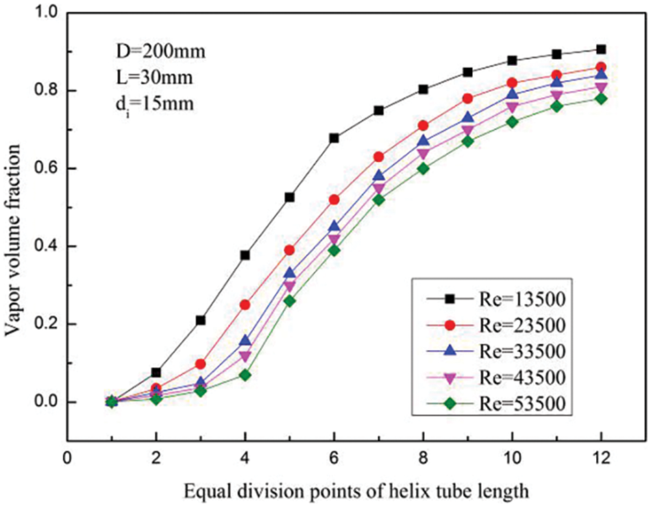
Figure 7: Variation of vapor volume fraction under differ Re
Fig. 8 shows the pressure change under different Re. The pressure distribution is close to linear when the Re is low. When the Re is greater than 33500, the pressure in the helix tube no longer changes linearly, and the pressure drop rate increases when the helix tube length increases. The area near the entrance of the helix tube is the single-phase heat exchange zone and gravity has a dominant effect on pressure drop. As the length of the helix tube increases, the LNG vapor volume fraction gradually increases. The frictional resistance and acceleration resistance become dominant factors to affect the pressure drop, so the decreasing rate of pressure become faster as the length of the helix tube increases.
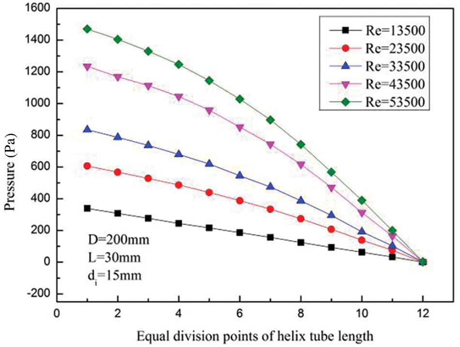
Figure 8: Variation of pressure under different Re
The Nusselt number Nu characterizes the intensity of convective heat transfer. In Fig. 9, the Nu changes under different Re can be seen. The results show that Nu increases when Re increases. The increase of Re will increase the turbulent flow intensity of LNG in the helix tube. Besides, the increase of the Re number results in an enhancement of the secondary flow, which is generated by the vortex, so the heat transfer boundary layer is destroyed through the secondary flow, and the efficiency of convective heat transfer increases.
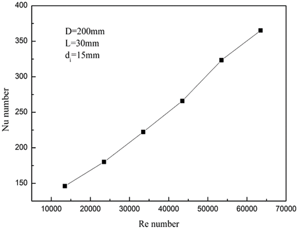
Figure 9: Variations of Nusselt number under different Re
As shown in Fig. 10, the heat transfer coefficient increases quickly at the LNG vapor volume fraction range of 0 to 0.2, and then slowly increases. The reason is that when the vapor volume fraction is from 0 to 0.2, the transition from liquid phase to vapor phase begins to occur. Meanwhile, the heat transfer process is transitioned from the single-phase flow to the nucleate boiling. The formation of bubbles effectively destroys the heat exchange boundary layer and the heat exchange wall surface is approximately a wet surface.
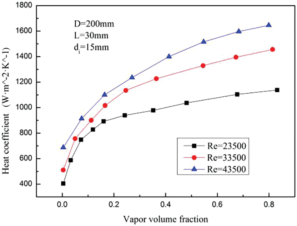
Figure 10: Variations of heat transfer coefficient with vapor volume fractions
3.2 Influence of Helix Tube Pitch L
Under the condition that D = 200 mm, Re = 33500, and di = 15 mm, variations of LNG vapor volume fraction distribution, pressure distribution and heat exchange efficiency in the HCTT heat exchangers is calculated at the helix tube pitch range of 30~50 mm. Figs. 11 and 12 show the distributions and variations of vapor volume fraction with different helix tube pitches. From Figs. 11 and 12, the change trend and magnitude of the vapor volume fraction under different helix tube pitch are not significantly different.

Figure 11: Distributions of vapor volume fraction with helix tube pitches
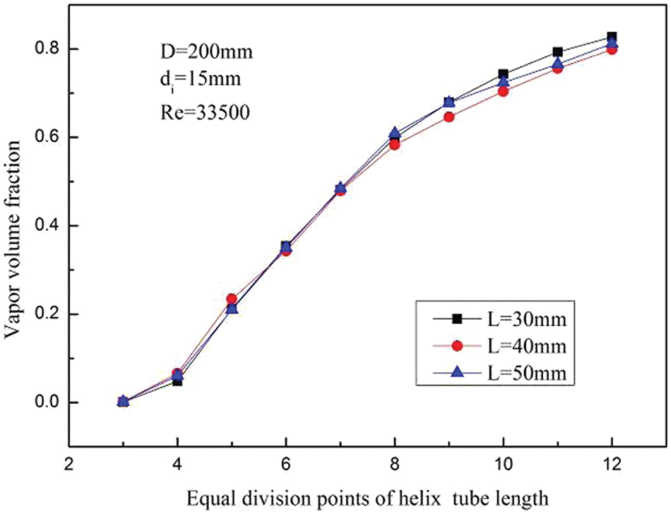
Figure 12: Variations of vapor volume fraction with helix tube pitches
Fig. 13 shows the pressure changes in the helix tube under different helix tube pitches. As the pitch of helix tube increases, the overall pressure loss in the helix tube decreases slightly. The reason is that as the helix tube pitch increases, the axial helix angle of the helix tube also increases, and the overall curvature of the helix tube becomes smaller, so the helix tube is closer to a straight tube. The resistance caused by the shape of the helix tube is reduced during the LNG flow, and the pressure loss is reduced.
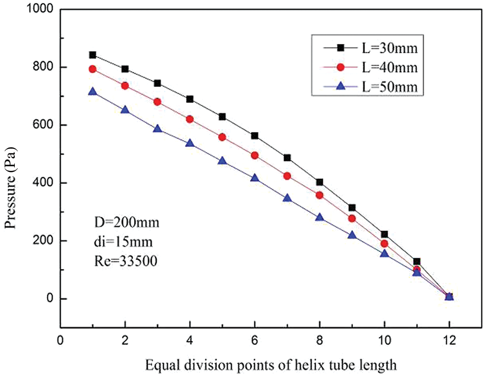
Figure 13: Variations of pressure with pitches
Fig. 14 shows the variations of Nu with L/di under the condition that the helix diameter and the inner tube diameter remain unchanged. The Nu has the same changing trend with L/di under different Re. The Nu decreases very little with the increase of helix tube pitches. In the range of L/di of 2.0 to 3.4, the Nu decreases by an average of 4.9% under different Re. The reason is that the increases in the helix tube pitches cause decreases in the curvature of the helix tube so that secondary flow in the LNG flow process is weakened which results in a decrease in heat exchange efficiency.
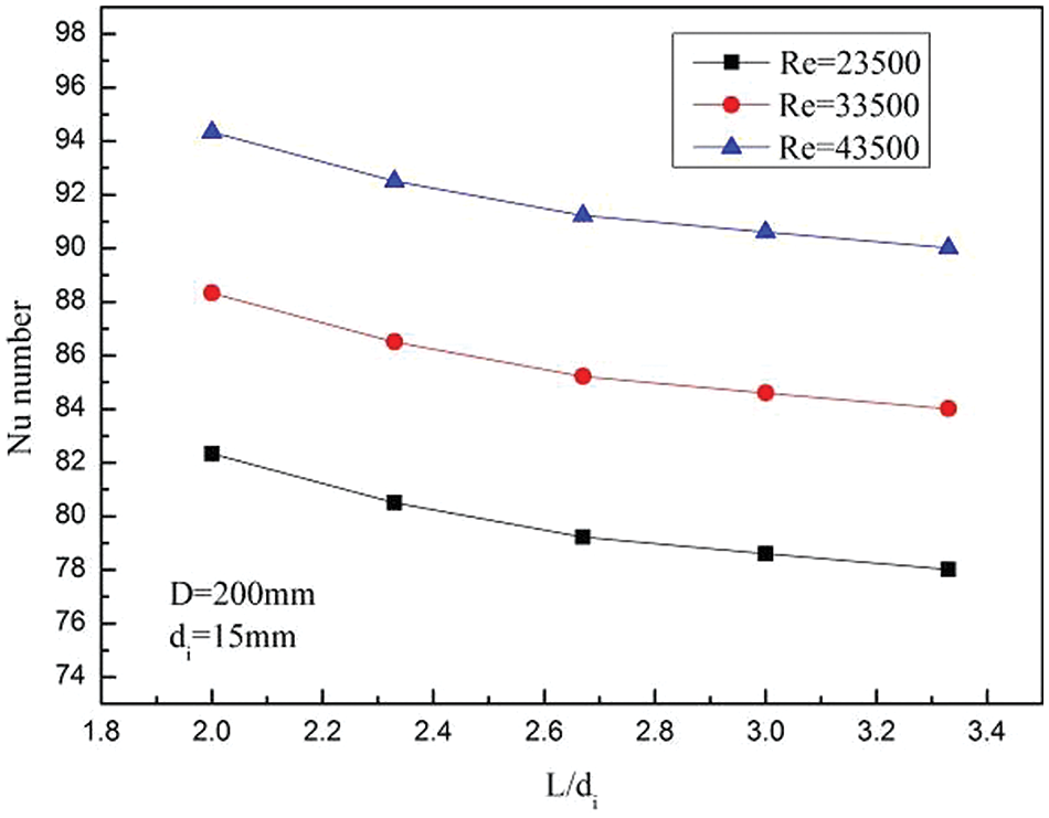
Figure 14: Variations of Nusselt number with different L/di
3.3 Influence of Helix Diameter of the Helix Tube D
Under the condition that L = 30 mm, Re = 33500, and di = 15 mm, variations of the LNG vapor volume fraction distribution, pressure distribution, and heat exchange efficiency in the HCTT heat exchangers are calculated in the helix diameter of helix tube range of 150~250 mm. Fig. 15 shows the distributions of vapor volume fraction under different helix diameters. Fig. 16 shows the variations of vapor volume fraction with different helix diameters. From Figs. 15 and 16, at the same equal division points of the helix tube length, the LNG vapor volume fraction decreases as the helix diameter of the helix tube increases. Under the condition that other geometric parameters of the helix tubes remain unchanged, the helix tube with a small helix diameter has a shorter LNG liquid phase flow length. The development of LNG liquid phase boiling is not complete. Therefore, the degree of vaporization of the helix tube with a small helix diameter is low.

Figure 15: Distributions of vapor volume fraction with helix diameters
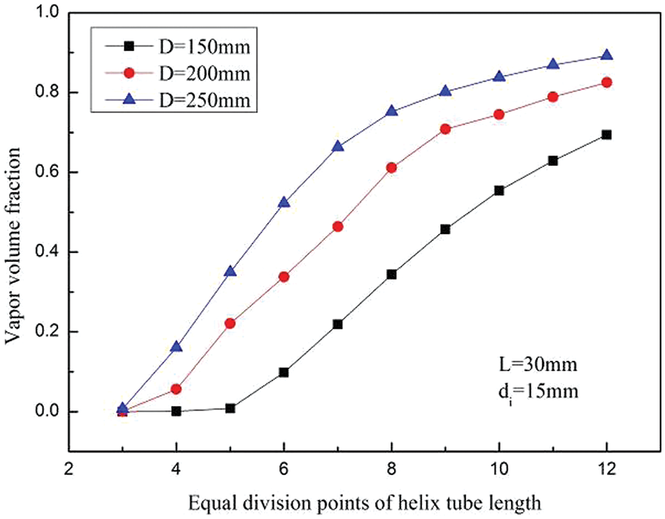
Figure 16: Variations of vapor volume fraction with helix diameters
Fig. 17 shows the variations of the pressure in the helix tube with different helix diameters of the helix tube. The magnitude of the pressure under different helix diameters of the helix tube is basically the same. As the helix diameter increases, the pressure loss increases slightly.
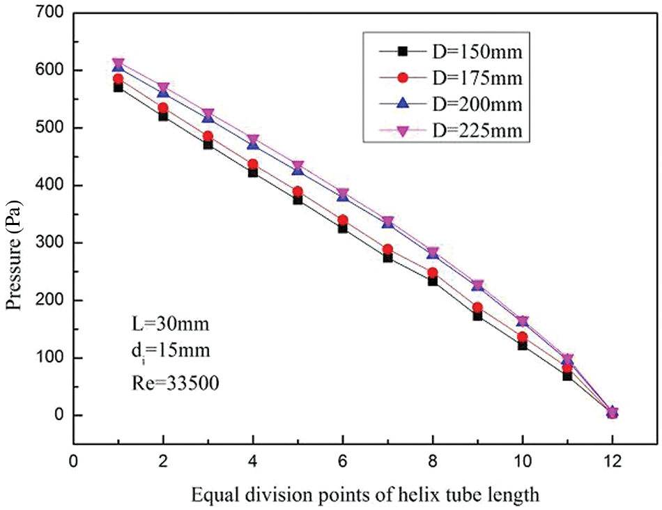
Figure 17: Variations of pressure with helix diameters
By searching for the relationship between the dimensionless parameters D/di and Nu, the heat transfer characteristics in HCTT heat exchangers can be obtained. Fig. 18 shows the variations of the Nu with the D/di under the condition that the inner tube diameter and helix tube pitch remain unchanged. The Nu decreases as the helix diameter of the helix tube increases. In the range of D/di from 10 to 16.76, the average reduction of Nu is 34.84% with different Re. The reason is that the helix diameter increases, the overall curvature of the helix tube becomes smaller, and the strength of the secondary flow in the LNG flow process is weakened. The disturbance of the secondary flow of LNG becomes weaker, which makes the thermal boundary layer difficult to be destroyed, and the heat exchange effect becomes worse.
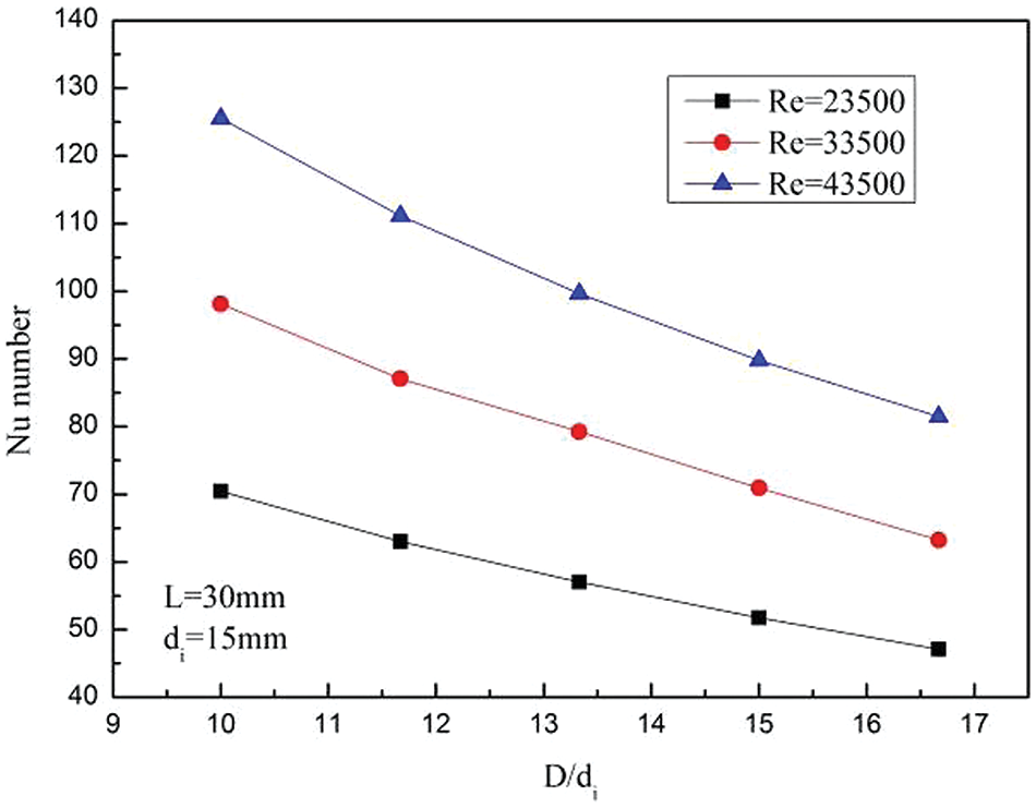
Figure 18: Variations of Nu with D/di
3.4 Influences of the Inner Tube Diameter of the Helix Tube di
Under the condition that L = 30 mm, Re = 33500, and D = 200 mm, variations of the LNG vapor distribution, pressure distribution, and heat exchange efficiency in the HCTT heat exchanger are calculated at the inner tube diameter range of 7.5~15 mm. Figs. 19 and 20 show the distributions of vapor volume fraction with inner tube diameters. From Figs. 19 and 20, at the same equal division points, the vapor volume fraction increases with the inner tube diameter decreases. When Re remains unchanged the decrease in inner tube diameter leads to a decrease in the mass flow of LNG. The reduction of the mass flow makes the rate of heat absorption and vaporization increase, and the degree of vaporization of LNG increases.

Figure 19: Distributions of vapor volume fraction with inner tube diameters
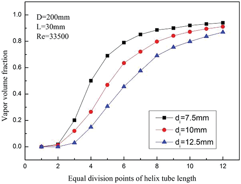
Figure 20: Variations of vapor volume fraction with inner tube diameters
As shown in Fig. 21, the variations of pressure under different inner tube diameters. Under the condition of different inner tube diameter, the total pressure change of LNG in the tube is basically the same. When the inner tube diameter decreases, the pressure drops faster at the beginning of the flow. The reason is that the frictional resistance and acceleration resistance increase as the inner tube diameter decreases when LNG starts to flow. When the liquid phase of LNG gradually transforms into the vapor phase, the frictional resistance of the vapor phase of LNG and the rate of pressure drop decrease.
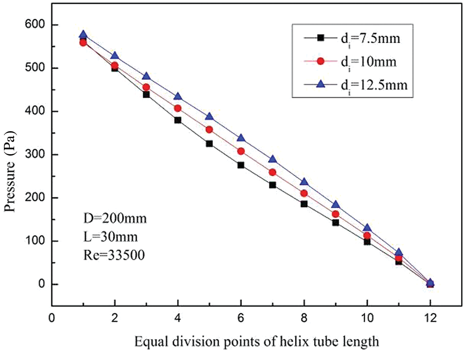
Figure 21: Variations of pressure with inner tube diameters
Fig. 22 shows the variations of the Nu with the D/di under the condition that the helix diameter and the helix tube pitch of the helix tube remain unchanged. The Nu decreases by an average of 43.17% under different Re in the range of D/di from 13.33 to 26.66. The Nu increases with the increase of the inner tube diameters. The reason is that the smaller the inner tube diameter, the stronger the restriction of the LNG flow in the helix tube. It is difficult for secondary flows to regenerate, so the heat transfer efficiency is reduced.
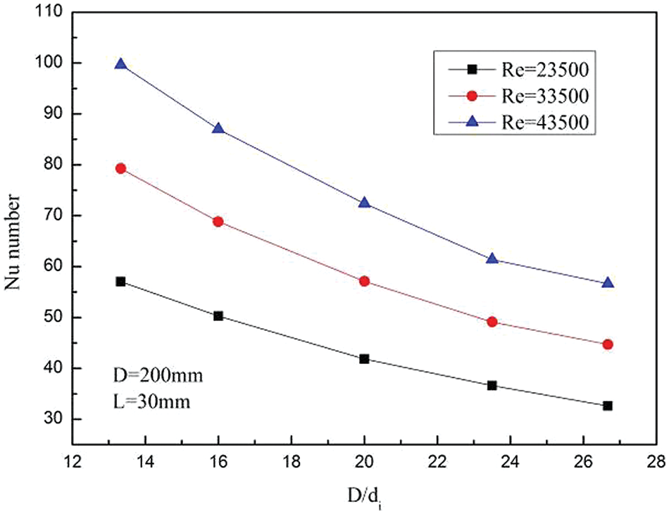
Figure 22: Variations of Nusselt number with D/di
4 Comparisons of Calculation Results with Existing Correlations
Under the conditions that di = 15 mm, D = 200 mm, system pressure is 0.5 MPa, and inlet Re is in the range of 20000–100000, the numerical calculation results are compared with the results of existing correlations, and the possible reasons for the differences between numerical calculation results and results of existing correlations are analyzed.
The Dn number [32] is used to measure the degree of turbulence of the secondary flow. Wongwises et al. [23] used the equivalent Dn number and Martinelli number
The calculation methods of liquid Rel number and vapor Reg number are expressed as Eq. (9).
Martinelli number
The correlation for calculating Nu proposed by Wongwises is expressed as Eq. (11).
Fig. 23 shows the comparisons between the numerical calculations results and the calculation results according to the above correlations. The deviation between the numerical simulation results and the calculation results of existing correlations is 72.3%, and the standard deviation is 23.6%. The calculation result of the correlations is much larger than that of the numerical calculation. The reason is that the calculation method of equivalent Dn number leads to a higher influence of mass flow on convective heat transfer in high vapor quality regions. The derivation of Wongwises correlations is based on a higher mass flow rate, so there is a large deviation from the numerical results.
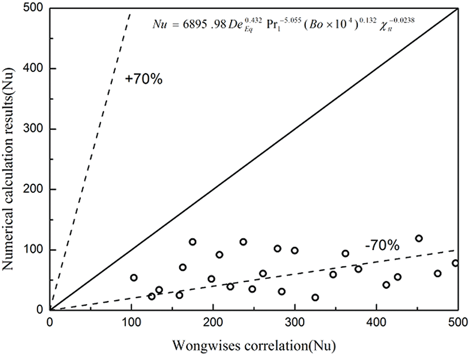
Figure 23: Comparisons of numerical results and Wongwises correlation
The numerical calculation result is compared with the calculation result of the correlation of Cui et al. [22]. Cui proposed the convective boiling number
Cui Nu correlation is:
Fig. 24 shows the comparisons between the numerical calculation results and the Cui correlation. The deviation between the numerical calculation results and the correlation is within 15%, the standard deviation is 5.4%, and the R-squared is 0.881. This means that the numerical calculation results are highly consistent with the results calculated through the correlation equations. The Nu of the LNG boiling flow in a helical tube can be empirically calculated by using the modified fitting formula.
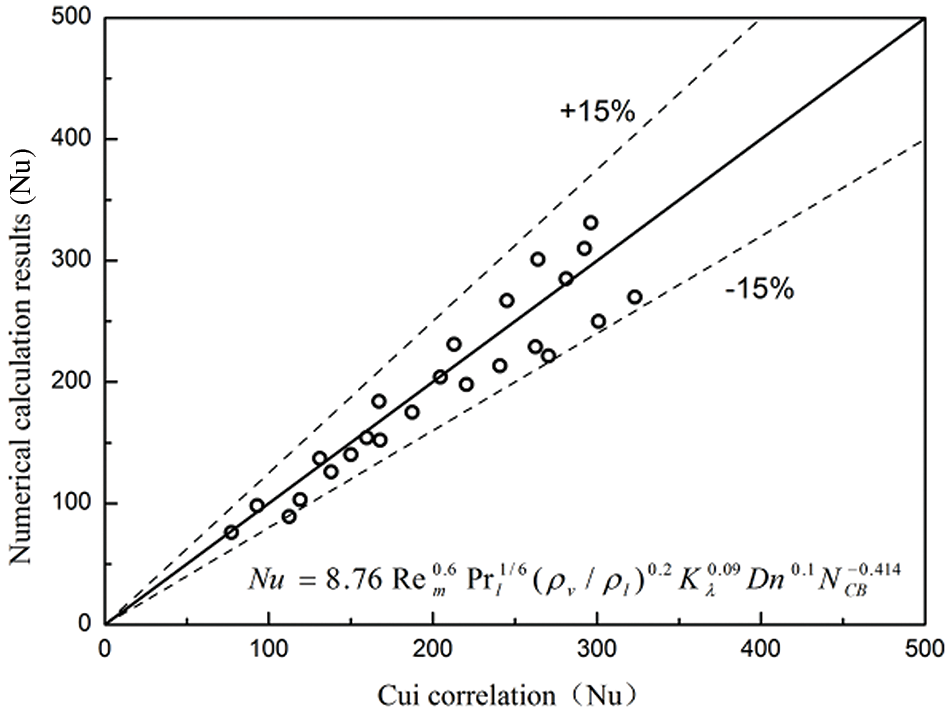
Figure 24: Comparisons of numerical results and Cui correlation
The effects of the inlet Re and the parameters of the helix tube on the degree of vaporization, pressure change, and heat transfer efficiency are numerically studied.
(1) The liquid phase of LNG affected by gravity and centrifugal force is close to the outer wall during the flow process, and the vaporization phenomenon starts from the inner wall first. The vapor volume fraction increases the fastest around the 5th to 7th equal points of the helix tube length, and the degree of vaporization is the most intense.
(2) When other conditions remain unchanged, increasing the inlet Re, increase the helix diameter of the helix tube, and decreasing the inner tube diameter will increase the vapor volume fraction. The helix tube pitch has very a minor impact on the vapor volume fraction.
(3) Under the condition that the inlet Re is lower than 33500, the pressure in the helix tube is approximately linearly distributed. Under the condition of high inlet Re, the pressure decreases faster with the increase of the length of helix tubes because of the frictional resistance and acceleration resistance. As the helix tube pitch decreases, the overall pressure loss will increase. The helix diameter of the helix tube and the inner tube diameter have little effect on the overall pressure loss.
(4) When the vapor volume fraction is at the range of 0~0.2, the heat transfer coefficient increases the fastest than other ranges.
(5) When other conditions remain unchanged, the Re increases, and the Nu increases; When inlet Re is 13500~53500, the Nu increases with the ratio D/di decreases; L/di has little effect on Nu.
(6) The numerical calculation result is compared with the calculation result of the correlation of Wongwises, the calculation deviation is 72.3%, and the standard deviation is 23.6%. Wongwises overestimates the size of the Nu, which may be due to the low mass flow used in the numerical calculation.
(7) The numerical calculation result is compared with the calculation result of the correlation of Cui. The deviation is within 15%. The standard deviation is 5.4%, and R-squared is 0.881.
Acknowledgement: The authors would like to thank the support of Shandong Jianzhu University for this study.
Funding Statement: This work is supported by Innovative Team Introduction Projects for New Universities in Jinan City (No. 2021GXRC075). URL: http://jnsti.jinan.gov.cn/attach/0/fd67c95066ff4b8a8408a10a5c960f8d.pdf (accessed on 2 December 2021).
Author Contributions: The author’s contributions are as follows: study conception and design: Fayi Yan; numerical simulation: He Lu, Shijie Feng; comparisons of results: Fayi Yan, He Lu; draft manuscript preparation: Fayi Yan, Shijie Feng. All authors reviewed the results and approved the final version of the manuscript.
Availability of Data and Materials: The data that support the study are available on request from the corresponding author.
Ethics Approval: Not applicable.
Conflicts of Interest: The authors declare that they have no conflicts of interest for the study.
References
1. Chen B, Zou TH, Li HQ, He W. Simulative and experimental research on the heat exchanger for cold energy recovery of liquefied natural gas. Appl Therm Sci. 2024;237(23):121798. doi:10.1016/j.applthermaleng.2023.121798. [Google Scholar] [CrossRef]
2. Wang GH, Wang DB, Peng X, Han LL, Xiang S, Ma F. Experimental and numerical study on heat transfer and flow characteristics in the shell side of helically coiled trilobal tube heat exchanger. Appl Therm Eng. 2019;149(12):772–87. doi:10.1016/j.applthermaleng.2018.11.055. [Google Scholar] [CrossRef]
3. Wang C, Cui ZY, Yu HM, Chen K, Wang JL. Intelligent optimization design of shell and helically coiled tube heat exchanger based on genetic algorithm. Int J Heat and Mass Trans. 2020;159(9–10):120140. doi:10.1016/j.ijheatmasstransfer.2020.120140. [Google Scholar] [CrossRef]
4. Pethkool S, Eiamsa-ard S, Kwankaomeng S, Promvonge P. Turbulent heat transfer enhancement in a heat exchanger using helically corrugated tube. Int Commun Heat Mass Transf. 2011;38(3):340–7. doi:10.1016/j.icheatmasstransfer.2010.11.014. [Google Scholar] [CrossRef]
5. Zhang C, Wang D, Xiang S, Han Y, Peng X. Numerical investigation of heat transfer and pressure drop in helically coiled tube with spherical corrugation. Int J Heat Mass Transf. 2017;113:332–41. doi:10.1016/j.ijheatmasstransfer.2017.05.108. [Google Scholar] [CrossRef]
6. Fouda A, Nada SA, Elattar HF, Refaey HA, Bin-Mahfouz AS. Thermal performance modeling of turbulent flow in multi tube in tube helically coiled heat exchangers. Int J Mech Sci. 2017;135(2):621–38. doi:10.1016/j.ijmecsci.2017.12.015. [Google Scholar] [CrossRef]
7. Liu SB, Huang WX, Bao ZW, Zeng T, Qiao M, Meng JC. Analysis, prediction and multi-objective optimization of helically coiled tube-in-tube heat exchanger with double cooling source using RSM. Int J Therm Sci. 2021;159(3):106568. doi:10.1016/j.ijthermalsci.2020.106568. [Google Scholar] [CrossRef]
8. Kirkara SM, Gonul A, Dalkilic AS. Enhancement of thermal and flow characteristics in helically coiled tubes with corrugated surfaces by Genetic Algorithm based optimization. Int J Heat Fluid Flow. 2024;106:109305. doi:10.1016/j.ijheatfluidflow.2024.109305. [Google Scholar] [CrossRef]
9. Mahdi JM, Abed AM, Al-Sadi HA, Khedher NB, Ibrahim RK, Amara MB. Augmenting the thermal response of helical coil latent-heat storage systems with a central return tube configuration. Case Stud Therm Eng. 2023;51:103657. doi:10.1016/j.csite.2023.103607. [Google Scholar] [CrossRef]
10. Wang N, Ghoushchi SP, Sharma K, Elbadawy I, Mouldi A, Loukil H, et al. Thermal performance enhancement in a double tube heat exchanger using combination of bubble injection and helical coiled wire insert. Case Stud Therm Eng. 2023;52(4):103722. doi:10.1016/j.csite.2023.103722. [Google Scholar] [CrossRef]
11. Cao Y, Abdous MA, Holagh SG, Shafiee M, Hashemian M. Entropy generation and sensitivity analysis of R134a flow condensation inside a helically coiled tube-in-tube heat exchanger. Int J Refrig. 2021;130:104–16. doi:10.1016/j.ijrefrig.2021.06.007. [Google Scholar] [CrossRef]
12. Wu JX, Li X, Liu HD, Zhao KL, Liu SL. Calculation method of gas-liquid two-phase boiling heat transfer in helically-coiled tube based on separated phase flow model. Int J Heat Mass Transf. 2020;161(19–20):120242. doi:10.1016/j.ijheatmasstransfer.2020.120242. [Google Scholar] [CrossRef]
13. Liang X, Xie YQ, Day R, Meng XH, Wu HW. A data driven deep neural network model for predicting boiling heat transfer in helical coils under high gravity. Int J Heat Mass Transf. 2021;166:120743. doi:10.1016/j.ijheatmasstransfer.2020.120743. [Google Scholar] [CrossRef]
14. Tsai MA, Chien LH, Hsu CY. Heat transfer enhancement of helical tubes during pool boiling. Int J Heat Mass Transf. 2023;211:124269. doi:10.1016/j.ijheatmasstransfer.2023.124269. [Google Scholar] [CrossRef]
15. Wu JX, Li Z, Li SG, Chen YB, Liu SL, Xia CJ, et al. Numerical simulation research on two-phase flow boiling heat transfer in helically coiled tube. Nucl Eng Des. 2022;395(1–2):111827. doi:10.1016/j.nucengdes.2022.111827. [Google Scholar] [CrossRef]
16. Chen S, Hu Z, Xiao Y, Gu H. Experimental investigation of subcooled flow boiling heat transfer in helical coils. Nucl Eng Des. 2018;327(5):187–97. doi:10.1016/j.nucengdes.2017.12.014. [Google Scholar] [CrossRef]
17. Moradkhani MA, Hosseini SH, Karami M. Forecasting of saturated boiling heat transfer inside smooth helically coiled tubes using conventional and machine learning techniques. Int J Refrig. 2022;143:78–93. doi:10.1016/j.ijrefrig.2022.06.036. [Google Scholar] [CrossRef]
18. Xiao Y, Hu ZX, Chen S, Gu HY. Experimental investigation of boiling heat transfer in helically coiled tubes at high pressure. Ann Nucl Energy. 2018;113:409–19. doi:10.1016/j.anucene.2017.11.052. [Google Scholar] [CrossRef]
19. Wu JX, Tang Z, Zhu YD, Li X, Wang HX, Shi Q. Two-phase secondary flow characteristics and heat transfer mechanism during boiling in a vertical helically coiled tube. Int Commun Heat Mass Transf. 2022;138(10):106398. doi:10.1016/j.icheatmasstransfer.2022.106398. [Google Scholar] [CrossRef]
20. Chen CG, Li XB, Zhang HN, Li FC. Numerical study on acoustic characteristics of flow boiling in a helical tube. Appl Therm Eng. 2024;247(3):123090. doi:10.1016/j.applthermaleng.2024.123090. [Google Scholar] [CrossRef]
21. Liaw KL, Kurnia JC, Sallih N, Mustapha M, Sasmito AP. Heat transfer analysis of subcooled flow boiling in copper foam helical coiled heat exchanger–a pore-scale numerical study. Int Commun Heat Mass Transf. 2024;155:107514. doi:10.1016/j.icheatmasstransfer.2024.107514. [Google Scholar] [CrossRef]
22. Cui W, Li L, Xin M, Jen T, Chen Q, Liao Q. A heat transfer correlation of flow boiling in micro-finned helically coiled tube. Int J Heat Mass Transf. 2006;49(17–18):2851–8. doi:10.1016/j.ijheatmasstransfer.2006.02.020. [Google Scholar] [CrossRef]
23. Wongwises S, Polsongkram M. Evaporation heat transfer and pressure drop of HFC-134a in a helically coiled concentric tube-in-tube heat exchanger. Int J Heat Mass Transf. 2006;49(3–4):658–70. doi:10.1016/j.ijheatmasstransfer.2005.08.017. [Google Scholar] [CrossRef]
24. Xie L, Xie Y, Yu J. Phase distributions of boiling flow in helical coils in high gravity. Int J Heat Mass Transf. 2014;80(3):7–15. doi:10.1016/j.ijheatmasstransfer.2014.08.094. [Google Scholar] [CrossRef]
25. Li C, Fang XD, Luo ZF, Da QM. Flow boiling heat transfer and pressure drop of R245fa inside horizontal 1.62 mm and 2.43 mm tubes under hypergravity. Int J Refrig. 2023;148(1):96–107. doi:10.1016/j.ijrefrig.2023.01.004. [Google Scholar] [CrossRef]
26. Onal BS, Kirkar SM, Skgul D, Celen A, Acikgoz O. Heat transfer and pressure drop characteristics of two phase flow in helical coils. Therm Sci Eng Progress. 2022;27(9):101143. doi:10.1016/j.tsep.2021.101143. [Google Scholar] [CrossRef]
27. Kurul N, Podowski MZ. Multidimensional effects in forced convection subcooled boiling. In: Proceedings of the Ninth International Heat Transfer Conference, 1990; Jerusalem, Israel; vol. 2, p. 21–6. doi:10.1615/IHTC9.40. [Google Scholar] [CrossRef]
28. Salehin M, Ehsan MM, Islam AS. Performance evaluation of nanofluid for heat transfer enhancement and pumping power reduction through a semicircular corrugated pipe. Model Measur and Cont B. 2017;86(1):296–311. doi:10.18280/mmc_b.860120. [Google Scholar] [CrossRef]
29. Mustakim A, Islam SM, Ahamed R, Salehin M, Ehsan MM. Numerical assessment of advanced thermo-hydrodynamic characteristics of nanofluid inside a helically featured straight pipe. Int J Thermofluids. 2024;21(2):100591. doi:10.1016/j.ijft.2024.100591. [Google Scholar] [CrossRef]
30. Lavieville J, Quemerais E, Mimouni S, Boucker M, Mechitoua N. Neptune CFD V1. 0, Theory manual. France: Electricite De France; 2005. [Google Scholar]
31. Murai Y, Inaba K, Takeda Y, Yamamoto F. Backlight imaging tomography for slug flows in straight and helical tubes. Flow Meas Instrum. 2007;18(5–6):223–9. doi:10.1016/j.flowmeasinst.2007.07.001. [Google Scholar] [CrossRef]
32. Brewster ME, Chung K, Belfort G. Dean vortices with wall flux in a curved channel membrane system: 1. A new approach to membrane module design. J Membr Sci. 1993;81(1–2):127–37. doi:10.1016/0376-7388(93)85037-W. [Google Scholar] [CrossRef]
Cite This Article
 Copyright © 2024 The Author(s). Published by Tech Science Press.
This work is licensed under a Creative Commons Attribution 4.0 International License , which permits unrestricted use, distribution, and reproduction in any medium, provided the original work is properly cited.


 Submit a Paper
 Propose a Special lssue
 View Full Text
 Download PDF
 Downloads
 Citation Tools