 Open Access
ARTICLE
Investigation of the Structure Design and Heat Transfer Characteristics of Heating Cable
1 School of Mechanical and Electrical Engineering, University of Shaoxing, Shaoxing, 312000, China
2 Department of Mechanical and Electrical Engineering, Xiamen University, Xiamen, 361002, China
3 Zhejiang Yuantong Cable Manufacturing Co., Ltd., Hangzhou, 311108, China
4 Zhejiang University of Technology, Key Laboratory of Special Equipment Manufacturing and Advanced Technology, Ministry of Education, Hangzhou, 310014, China
* Corresponding Author: Yanmin Zhang. Email:
(This article belongs to the Special Issue: Two-phase flow heat and mass transfer in advanced energy systems)
Frontiers in Heat and Mass Transfer 2024, 22(5), 1477-1492. https://doi.org/10.32604/fhmt.2024.052675
Received 11 April 2024; Accepted 03 July 2024; Issue published 30 October 2024
Abstract
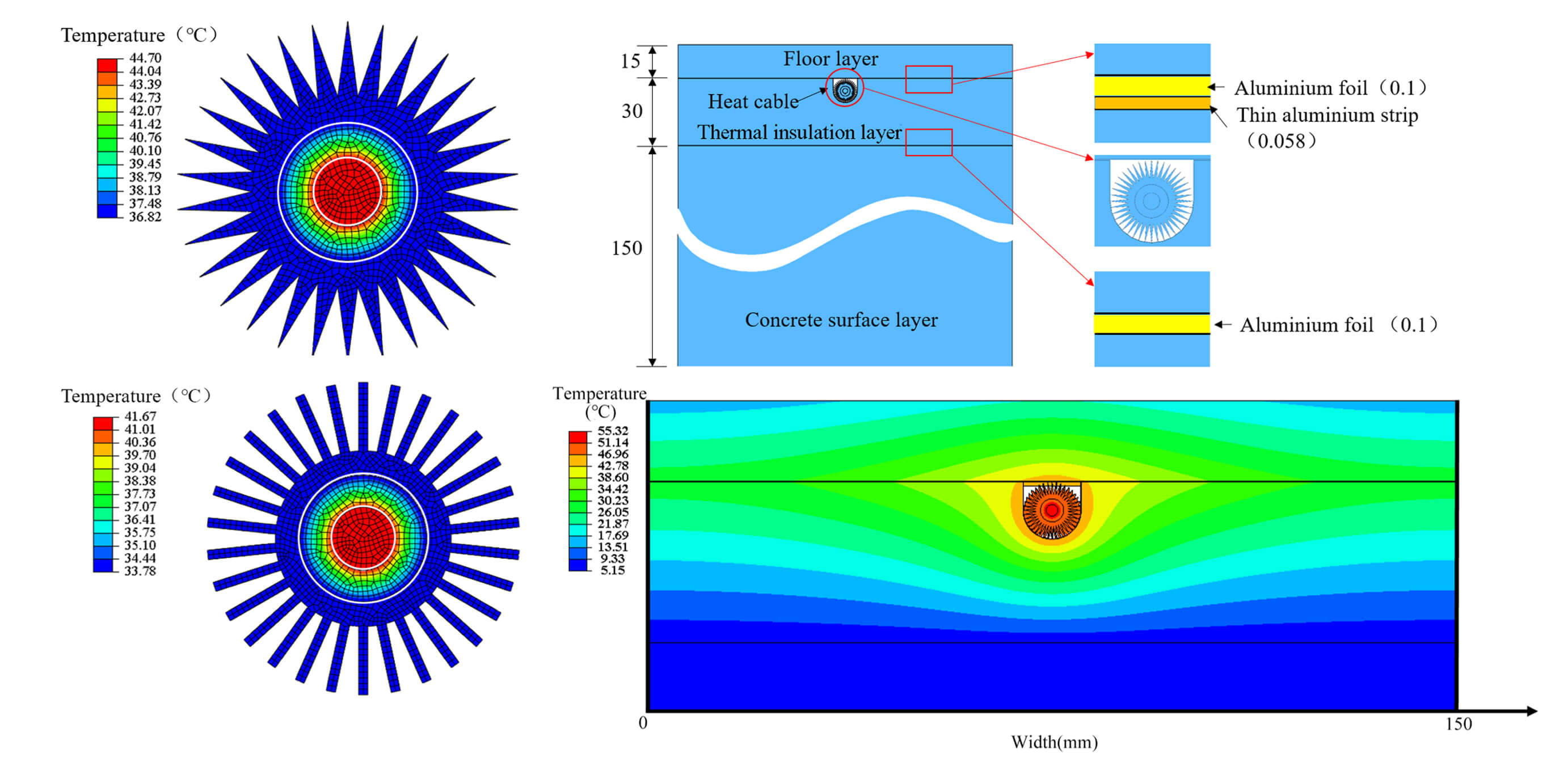
Indoor heating with an electrical heating cable, which has no harmful emissions to the environment, is an attractive way for radiant floor heating. To improve the heat transfer efficiency, a novel structure of the heating cable was designed by proposing the concept of the aluminum finned sheath. The transient heat transfer model from the embedded heating cables to the floor is established to validate the feasibility of this novel cable. The effects of the fin number and shape on the cable’s temperature and heat flux distribution were analyzed. The results show that, with the specific volume of the sheath, increasing the number of fins can enhance the thermal diffusion capacity of the heating cable and reduce its temperature. Rectangular fins exhibit higher performance for heat dissipation than triangular fins due to their larger surface area. The simulation result shows that the floor temperature above the cable rises from 5°C to 22.5°C after a 2-h heating process, which was validated with experimental results. The results and suggestions can provide reference to guide the design of the heating cable.Graphic Abstract
Keywords
Nomenclature
| A | Area (mm2) |
| C | Specific heat (J kg−1K−1) |
| IH-EHC | Indoor heating with electrical heating cable |
| NiAl | Nickel-aluminium alloy |
| N | Fin number |
| S | Surface area (mm2) |
| V | Volume (mm3) |
| XPLE | Cross-linked polyethylene |
| XPS | Extruded polystyrene board |
| λ | Thermal conductivity (W m−1K−1) |
| ρ | Density (kg m−3) |
| t | Time (s) |
| θ | Angle (°) |
| Subscripts | |
| S | Sheath of heating cable |
| in | Inner radius of the fin |
| out | Outer radius of the fin |
With the development of low carbon, the traditional coal-based heating technology in China is facing huge challenges. To mitigate the emissions from coal burning, electric heating technology has developed rapidly in recent years [1]. As one of the electric heating technologies, the heating cable has no gas emissions, and is widely applied in places and objects requiring heating and heat preservation, especially for the domains in snow/ice melting of road and roof surface, indoor heating, anti-freezing and insulation of chemical pipelines [2–6]. With the improvement in living standards, there is also a demand for heating in southern cities in winter. However, winter in the South may only have a few random freezing days, and the traditional water heating system, once turned on, is usually left on for a long time, which makes it wasteful when used in the South [7]. Heating cables are considered to be a suitable method to meet short-term heating demands. Up to date, the large-scale commercial application of heating cable is greatly limited, due to the complicated heat transfer (multiphase heat transfer integrating heat conduction, convection and radiation) [8].
Extensive research has been carried out on the heat transfer performance of heating cables in various environments. Yang et al. [9] found that snow and ice melting using heating cables has less damage to the environment and higher thermal efficiency compared to traditional methods. Su et al. [10] found that when the ambient temperature was as low as −7.5°C~−2.2°C, the heating cable technology could raise the temperature of the airport pavement by 13°C within 2.5 h, effectively improving the safety of the airport runway in freezing weather. Danilovic et al. [11] showed that heating cables could be used in oil wells to solve the problem of paraffin deposition. Tan et al. [12] investigated the temperature rise and ice melting patterns of heating cables fabricated by different metal wires, which could provide references for the design of actual bridges and roads. In the construction of the 2022 Winter Olympic Village, Liu et al. [13] compared different heating methods, and finally decided to use a heating cable. Some numerical methods, such as the finite element method, are used to simulate the heat-up process of heating cables and the results of these studies guide the practical application of heating cables in the room [14–16].
The above researches illustrate the feasibility of the heating cable technique, but as seen from the structure of the heating cable, its heat transfer characteristics are limited. The heating cable is composed of heating alloy, insulation layer, and sheath [17]. At present, most of commercial heating cable uses PVC as sheath material, which is at a low price, but the performance is less than satisfactory, especially since the heat conductivity is poor. Therefore, we propose to use a metal sheath to improve its heat transfer performance, and meanwhile enhance the mechanical strength and corrosion resistance. The material of aluminum is a good choice as it is light, and has a good shielding ability from electromagnetic radiation [18], which can improve the safety of the user, especially when the heating cables are applied in indoor heating. To further improve the heat dissipation efficiency of the heating cable, the structure of fins on the surface of the aluminum sheath is chosen to increase the heat dissipation area.
The methods to enhance heat transfer mainly include increasing heat transfer area, heat transfer temperature difference and heat transfer coefficient [19,20]. The fin is an effective way to strengthen heat transfer by increasing the heat transfer area, which is applied in heat exchangers of various industries, such as electronic components [21] and batteries [22–25]. Extensive research has been conducted to investigate the effect of different fin parameters on the heat transfer performance. The shape of the fins is an important feature that affects the heat transfer efficiency of finned heat exchangers. He et al. [26] established a heat dissipation model of the thermoelectric cooler hot side with a plate-fin sink to explore the performances of the plate-fin sink with different shapes, convection conditions and arrangements. A multi-objective optimization of the fins was proposed based on artificial neural networks (ANN) and non-dominated sorting genetic algorithm (NSGA-ІІ) in order to optimize the fin geometry. Liu et al. [27] studied the effect of fin spacing on the heat exchange performance of finned heat exchangers, and the results showed that either too large or too small fin spacing was not conducive to the best performance of heat exchange. Yang et al. [28] studied the effect of different fin parameters on the heat transfer performance of finned tubes, and validated their effectiveness through numerical simulation and physical experiments. The results showed that the outlet temperature of the heat exchanger has increased from the previous 28.6°C to 37.2°C, and the efficiency of heat transfer has been significantly improved.
In this paper, a novel all-aluminum clad heating cable is proposed to enhance the heat dissipation efficiency and other related properties of the heating cable by improving the material and structure of the outer sheath.
2 Structure Design of Heating Cable
The heating cable is mainly composed of three layers, including the inner heating alloy wire, the middle insulation layer and the outer sheath. When the power turns on, heat is generated by the heating alloy wire, and then transfers to the floor through multiple layers. The newly designed heating cable is shown in Fig. 1. It includes the heating alloy, insulation and sheath with triangular fins. The dimensions of the heating cable are defined as follows. The length of the heating cable along the z-direction is defined as l. The radius of the heating alloy and insulation are r1 and r2, respectively. The inner radius, r3in and outer radius r3out, along with the intersection angle θ, are defined as the fin shape parameters for the triangular fin. There are N fins in total along the outer circumference of the sheath. Based on the above parameters, the volume and surface area of the sheath can be calculated by Eqs. (1) and (2), respectively,
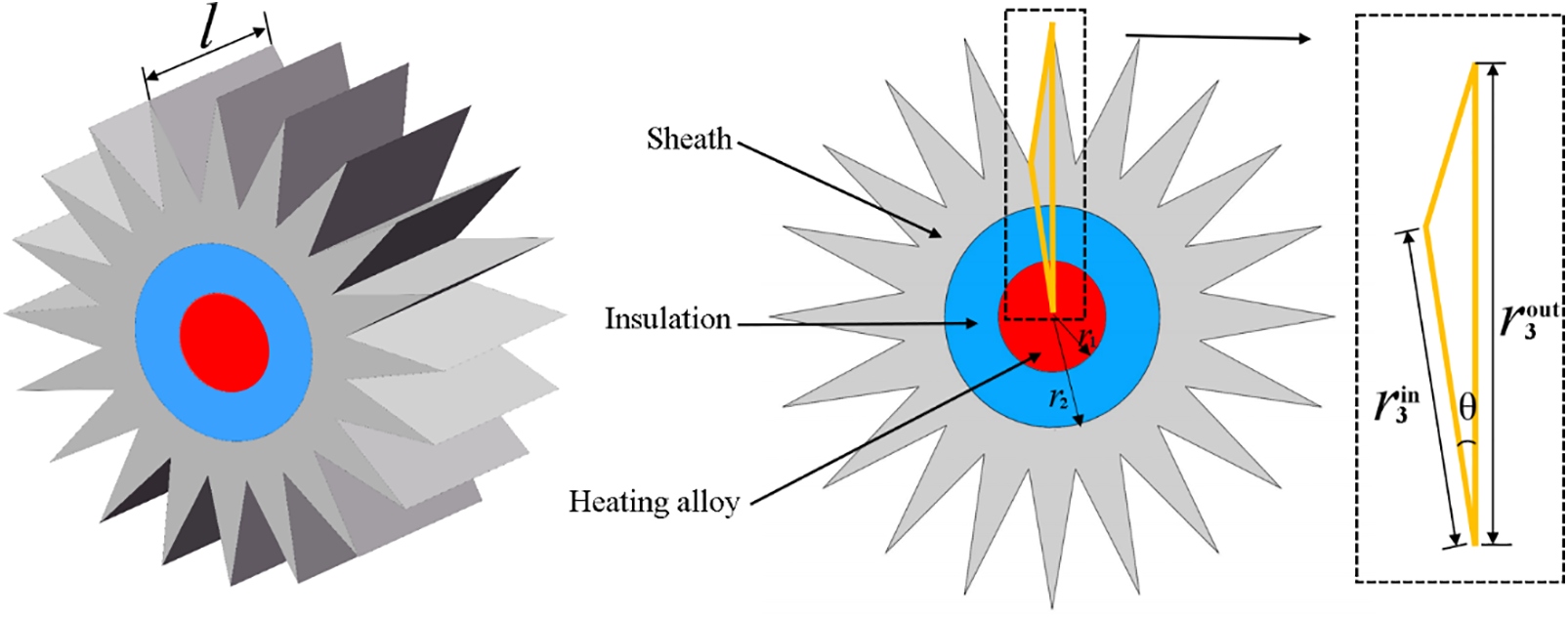
Figure 1: The structure of the heating cable
The volume of the sheath (Vs) determines the consumption of aluminum, and surface area As is the total heat dissipation area.
The influence of fin parameters on heat dissipation performance was investigated under the same volume of sheath material, in order not to increase the material cost of heating cable. As shown in Fig. 2, although the number of fins vary, the volume of the sheath is constant.
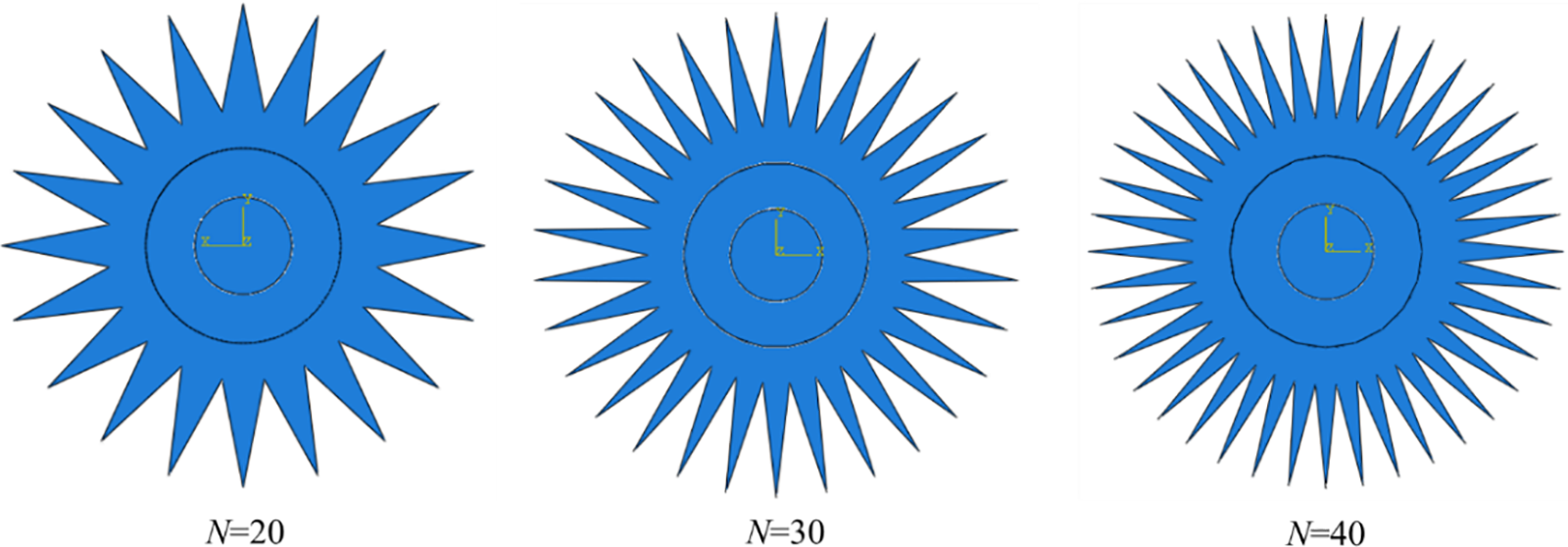
Figure 2: Geometry of heating cables with different fin numbers
3 Thermal Simulation of the Heating Cable
A pure heating cable that is not embedded under the floor for use was taken into consideration. The heating alloy, insulation layer and sheath materials are nickel-aluminum alloy, cross-linked polyethylene (XPLE) and 6061 aluminum alloy.
The modeling of the heated cable is performed under the following assumptions. (1) The electric heating cable is uniform along the length direction (z-axis). (2) The contact thermal resistance between different materials is ignored. The heat transfer of the heated cable was modeled as a two-dimensional transient heat conduction problem, while the heating alloy in the middle is regarded as the heat source. The energy equation in the model where the coordinate system is r-θ-z in Fig. 3 can be written by using Fourier’s law as follows [29]:
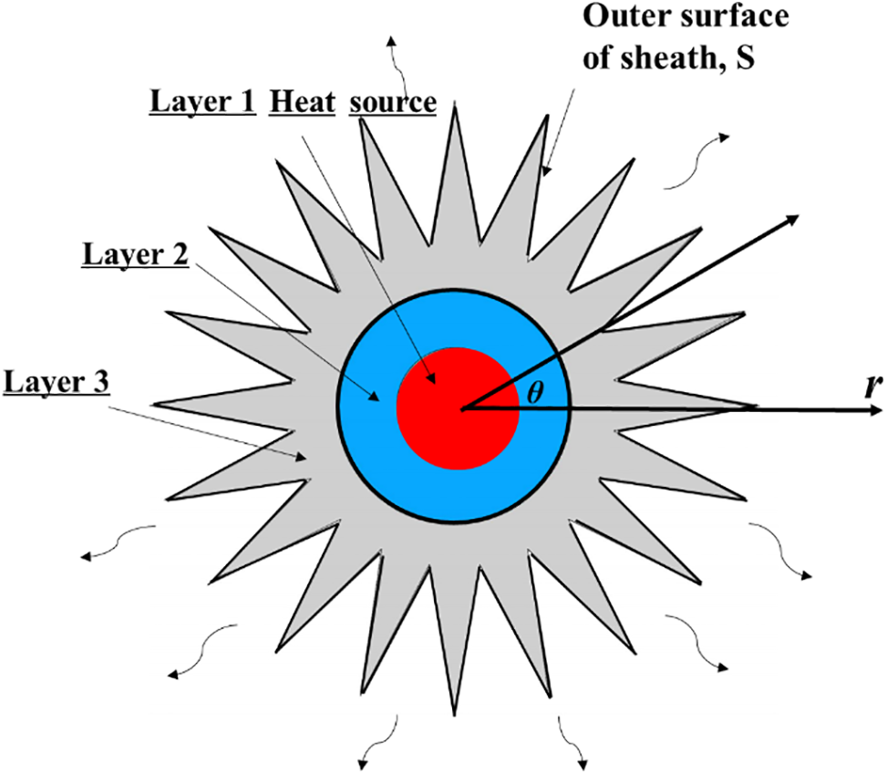
Figure 3: The heat transfer of the heating cable
The governing equation is subject to the following initial conditions:
The boundary conditions are expressed by Eq. (5). The sheath has convection heat transfer with the air. The outer surface of the sheath is defined as S.
The continuous conditions between the electric heated alloy and the insulation, and between the insulation and the aluminum fin are expressed by Eqs. (6)–(9).
Ti is the temperature of the heating cable, and i (i = 1, 2, 3) represents the layers of heating alloy, insulation and sheath, respectively. λi, ρi and Ci are the thermal conductivity, density and specific heat capacity of each material, as listed in Table 1.

The thermal simulation based on the finite element (FE) model was used to investigate the heat transfer performance of the heating cable with Aluminum finned structure through ABAQUS. According to the mathematical model, a detailed finite element model was built, as shown in Fig. 4. The 2-D geometry was meshed using the quadrilateral element. The meshes with different sizes are applied to perform the grid independence analysis. As shown in Fig. 5, the maximum temperature is 52.24°C, 52.37°C and 52.47°C corresponding to the grid numbers 834,1631 and 3486, which indicates the current grid density has little effect on temperature results. The grid number of 1631 is adopted for computation. For the analysis of time step independence, a series of different step sizes (5 to 40 s) are taken for calculation. The temperature difference is 0.59°C under maximum and minimum time steps. Therefore, the time step of the 20 s is selected for balancing the calculation accuracy and efficiency.
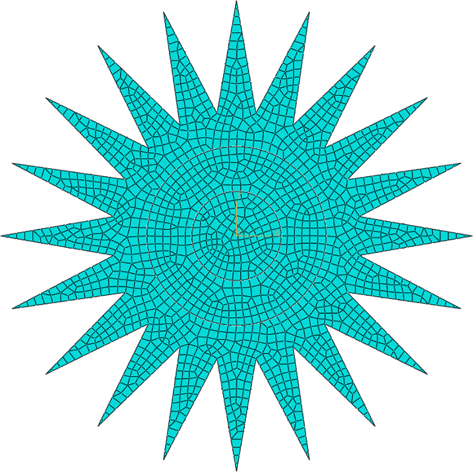
Figure 4: The FE meshing of the simulation for the heating cable

Figure 5: Temperature results with different mesh density
In our previous experiment, a heating cable with a length of 107 m was used, and the total power was 3 kW. Therefore, the power per volume is calculated by using the total power divided by the volume of the heating alloy, which is 7.65 × 10⁶ W/m3. The convective heat transfer coefficient is set as 6 W/(m2K) and the initial and ambient temperatures are 5°C.
3.3 Simulation Results and Analysis
The influence of the number and shape of fins on the temperature was studied. In order not to increase the material cost, the volume of the aluminum sheath remains unchanged. The volume was set as 178 mm3. The length of the heating cable along the axial direction is set to be l = 5 mm. So, the area of the aluminum sheath is determined as 35.6 mm2, which is used in the two-dimensional heat transfer problem. Therefore, when the number or shape changes, the rest of the fin shape parameters will change accordingly. The simulation duration is 10 min.
3.3.1 The Effect of the Fin Number on Temperature Response
The number of fins, N = 20, 30 and 40 are taken, respectively, and the fin Angle θ (=360°/2N) and outer radius of sheath r3out changes according to Eq. (1). Table 2 lists the fin shape parameters and the corresponding volume and surface area of sheath under different fin numbers.

The simulation results of different fin numbers are shown in Fig. 6. Temperature decreases as N increases. When N increases from 20 to 40, the average temperature of the heating cable declines from 48.5°C to 33.4°C. It indicates that more heat is diffused to the environment under larger N, since the total heat generation remains constant in our simulation. Therefore, a larger number of fins is beneficial to the heat dissipation of cable to the environment, and meanwhile reduces its own temperature increase, which is conducive to the anti-aging of insulation materials. The insulation of the heating cable will accelerate the aging rate under long-term high-temperature operation, which will affect the cable’s operating life [30].
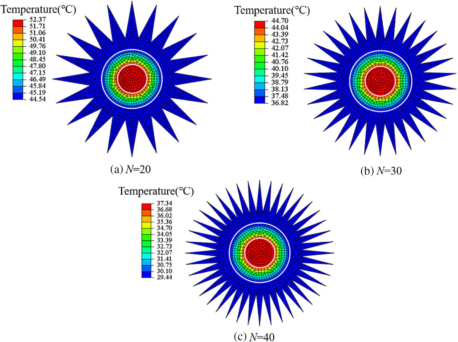
Figure 6: The effect of N on the temperature distribution of the heating cable
Due to the radial symmetry of the heating cable in geometry and boundary conditions, each fin has the same temperature distribution. To investigate the effect of N on transient fin temperature, five points were depicted from the root to the top of the fin, as shown in Fig. 7, which were used to calculate the average fin temperature. It is noted that although the length of the fins varies with its number to ensure the same volume, the five points are all chosen equidistant from the root to the top of the fin.
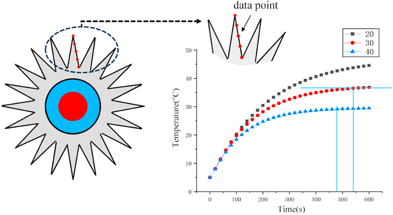
Figure 7: The effect of N on fin temperature
In Fig. 7, it can be observed that the fin temperature rises rapidly at first, and then tends to be stable. That is, the heating process changes from a non-steady state to a steady state. It is worth noting that, under different fin numbers, the time when the fin temperature reaches the steady state is different. For N = 20, the heating process did not reach the steady state when t = 600 s. For N = 30 and N = 40, the steady state is achieved at about t = 500 s and t = 400 s. The reason for this phenomenon is that the surface area of the fin changes with N. When N increases from 20 to 40, the surface area increases from 488 to 944 mm2, which makes the fin to dissipate the heat more efficiently, to reach the thermal equilibrium faster.
The heat flux of the heating cable under different fin numbers is shown in Fig. 8. It is the heat flux of the system at the isothermal surface. As to the distribution of heat flux, the inside and outside of the heating alloy show different rules. In the 2-D heat transfer model, the heating alloy is considered as a surface heat source, so the magnitude of heat flux inside the heating alloy increases with its area. However, outside the heating alloy, the magnitude of heat flux is inversely proportional to the area of heat flow, so it decreases from the insulation layer to the fin layer along the radial direction.
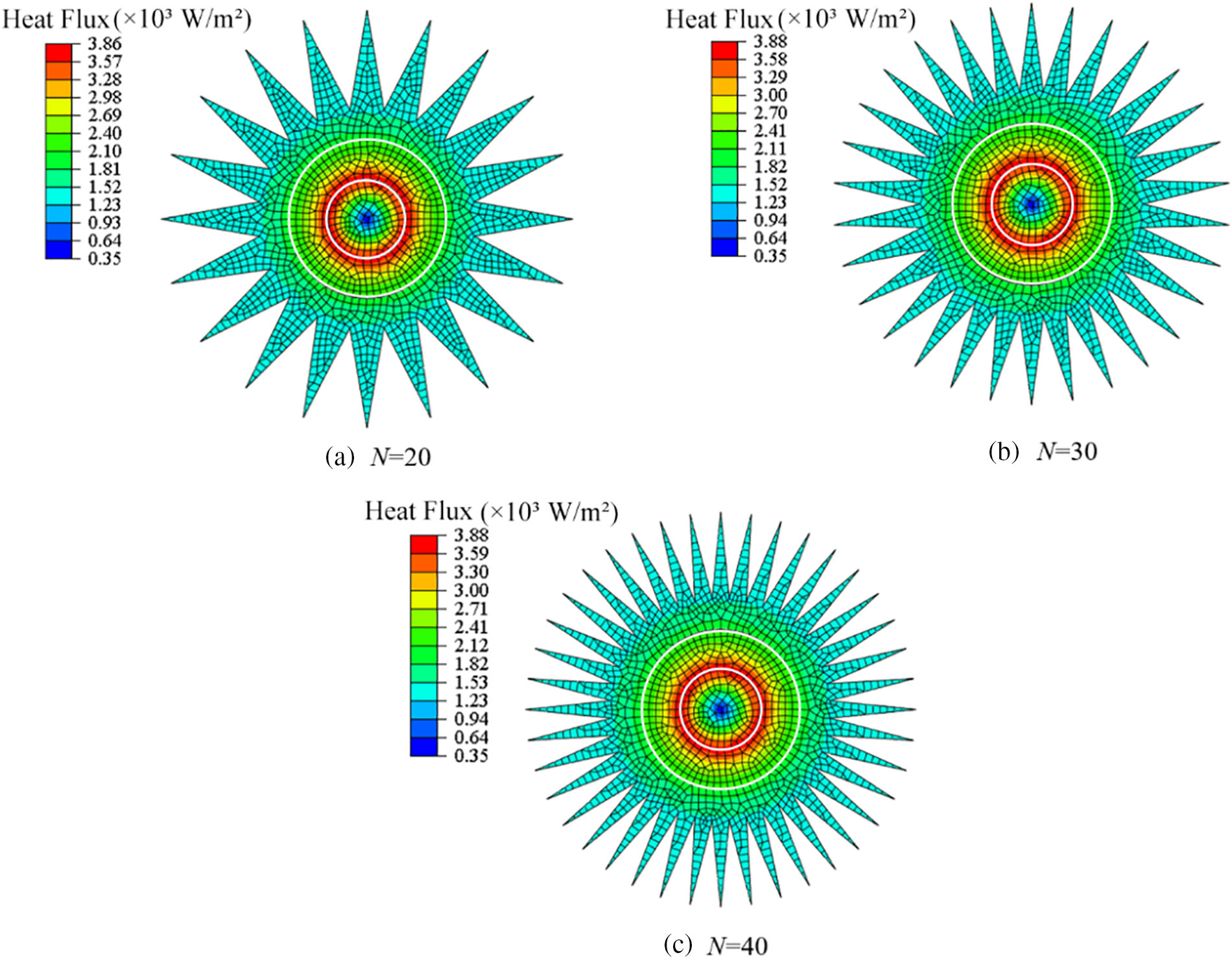
Figure 8: The effect of N on heat flux of heating cable
The maximum heat flux appears at the inner side of the insulation layer. When the thermal system is in a steady state, the maximum heat flux can be calculated by dividing the total heat generation of the heating alloy by the area of the inner surface of the insulation, that is
3.3.2 The Effect of Fin Shape on Temperature Response
The fins of different shapes, rectangular and triangular, were designed to investigate the effect of fin shapes on the heat transfer performance of heating cables. The volume of the sheath is maintained constant for both types of fins. Taking into account of the manufacturing issue, the spacing of rectangular fins is set as π/10. The fin shape parameters, the corresponding surface area and the volume of the sheath are listed in Table 3.

In Fig. 9, the average temperature of the rectangular fin is 37.7°C, lower than that of the triangular fin 40.8°C. It indicates that the rectangular fin has a better heat dissipation effect due to a larger surface area (shown in Table 3). The corresponding heat flux distribution is shown in Fig. 10. The magnitude and distribution of these two heat fluxes are close. For the rectangular fin, it is observed that the heat flux in the tip of the fin is smaller than the triangular fin, which is mainly attributed to the longer length of the rectangular fin.
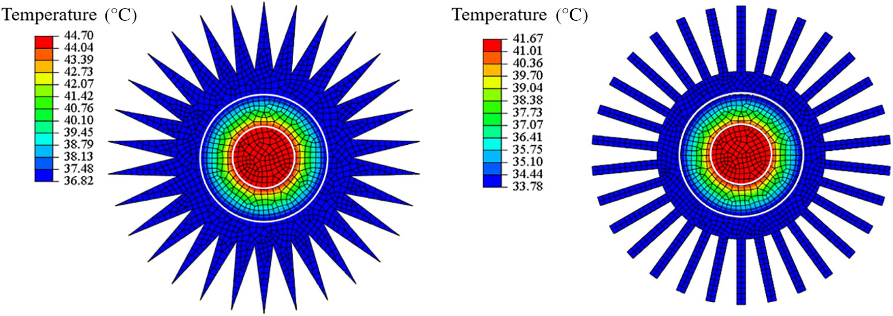
Figure 9: The effect of fin shape on the temperature of the heating cable
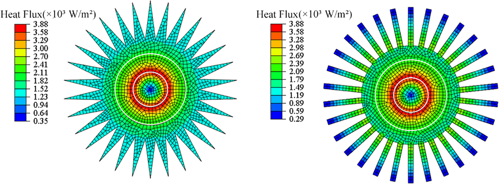
Figure 10: The effect of fin shape on heat flux of heating cable
4 Thermal Simulation of the Cable-Heated Floor
To investigate the temperature of the cable-heated floor, the structure of indoor heating with electrical heating cable (IH-EHC) is established, as shown in Fig. 11. The heating cables are embedded in the prefabricated hole of the insulation layer. The floor layer, which is made of wood, is located on top of the heating cables. The concrete layer is located at the bottom. The upper and lower surfaces of the insulation layer are covered with a small thickness of aluminum foil and thin aluminum strips, which are used as a cable shielding material to resist electromagnetic waves, radio frequency interference and noise. It is noted that only triangular fins can be manufactured now due to the limitation of the equipment. Therefore, triangular fins are applied here to validate with the experimental results.
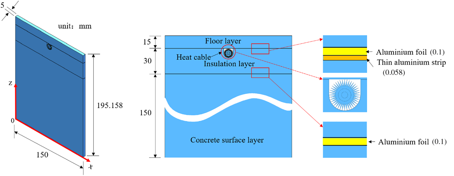
Figure 11: The simplification of the structure of IH-EHC
The thermal modeling is performed under the following assumptions: (1) The bottom boundary is adiabatic because the concrete surface layer is under the thermal insulation layer. (2) The top surface has a convective and radiative boundary condition with the room air. (3) The contact thermal resistance between different layers is ignored. The convective heat transfer coefficient is set at 6 W/(m2K), the radiation coefficient of the floor surface is 0.82, and the ambient temperature is 5°C [31]. The thermal properties of different materials in IH-EHC are shown in Table 4.

To verify the numerical result, an experimental setup was established (as shown in Fig. 12), and the materials were laid in accordance with the simulation model. A floor layer, a thin aluminum strip, a heating cable, an aluminum foil, an insulation board and a plastic pallet are stacked from the top to bottom. Since the heat is almost controlled in the thermal insulation layer, it will not cause errors to use the plastic pallet to substitute the concrete layer. Two thermocouples are placed on the floor surface directly above the heating cable to measure the temperature rise, as shown in Fig. 13.

Figure 12: Experimental (a) design, and (b) set up for indoor heating with an electrical heating cable
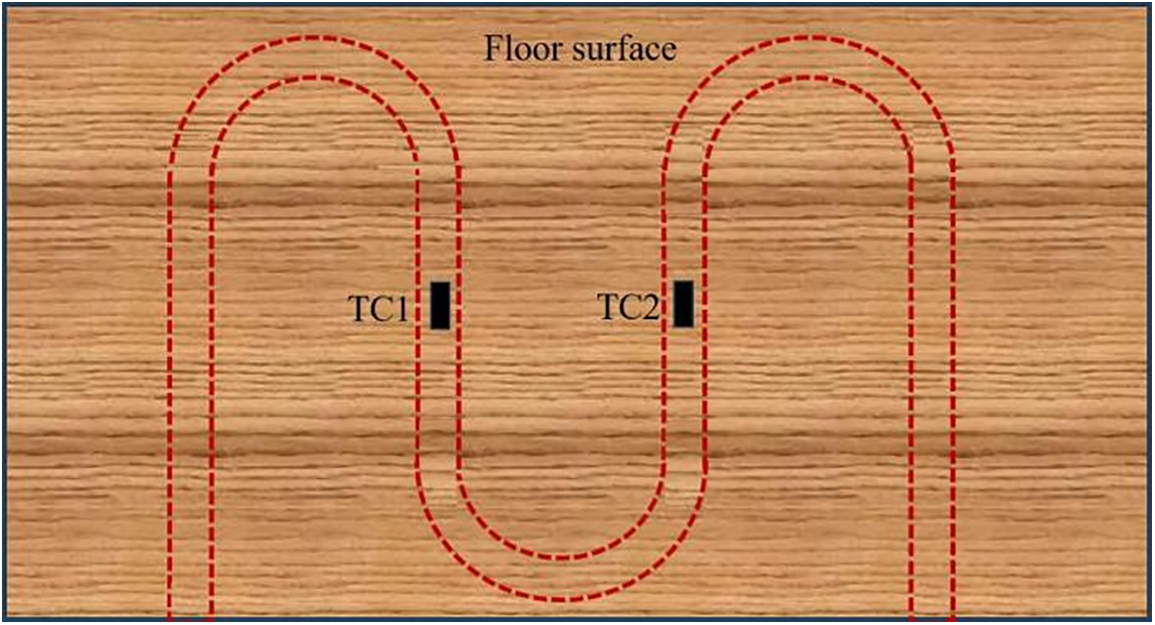
Figure 13: Thermocouples arranged on the floor surface
The simulated temperature distribution of IH-EHC after 2 h is shown in Fig. 14. The temperature is symmetrically distributed along the center line in the width direction. The heating cable has a maximum temperature of 55°C, which is lower than the melting point of the materials of the heating cable, including the nickel-aluminum alloy, cross-linked polyethylene, and 6061 aluminum alloy, and can ensure the safety of the cable. The bottom surface of the insulation layer has the minimum temperature, indicating the insulation layer has a good thermal insulation effect, and little heat is transferred down to the cement layer.
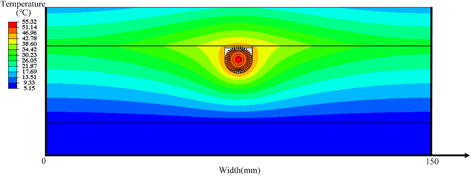
Figure 14: Floor temperature field with built-in heating cable
The heat generated by the cable is gradually transferred to the floor. After 2 h, the peak temperature on the floor surface is 22.5°C, appearing right above the heating cable. This numerical result is compared by experimentally measured temperature, as shown in Fig. 15. The temperature difference is lower than 2°C, which verifies the accuracy of the thermal model. As to the floor temperature distribution along the width direction, an uneven temperature field was observed in Fig. 16. This is a normal phenomenon since the volume of the heating cable is relatively small compared to the floor. Therefore, when the heating cable is used in indoor floor heating, the laying interval of the cables needs to be carefully considered.
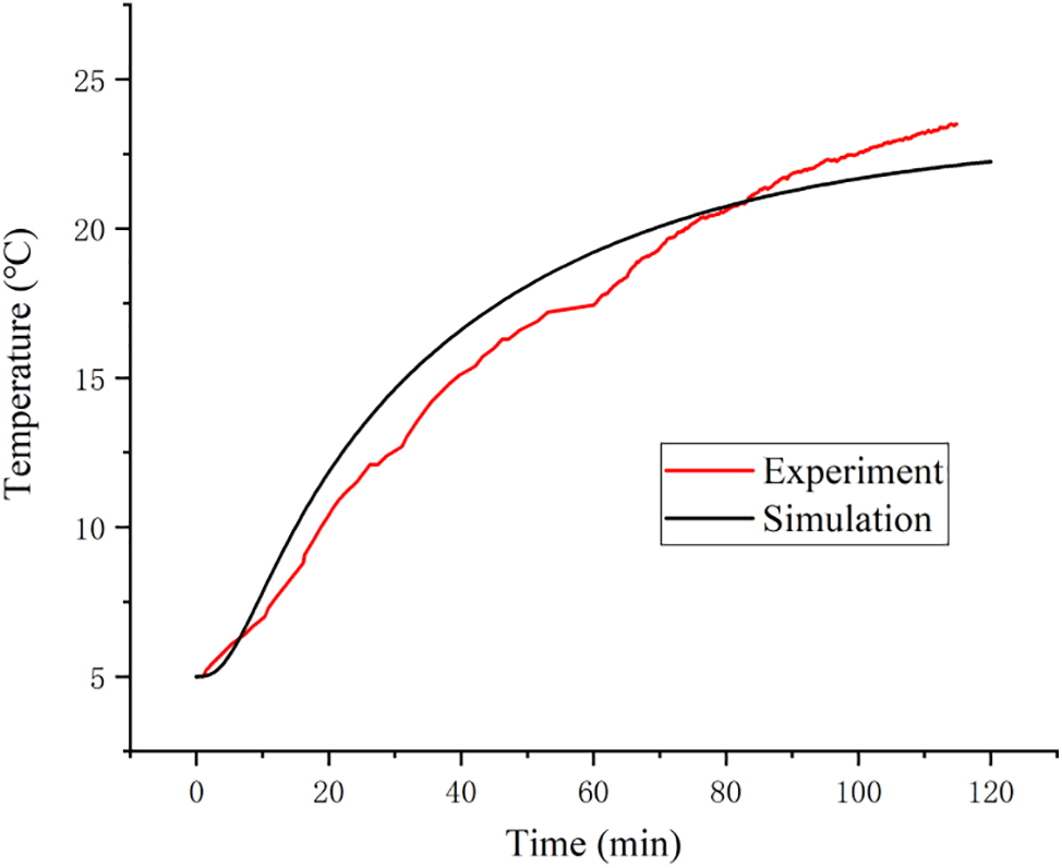
Figure 15: Experimentally measured and simulated temperature in the center of the floor surface
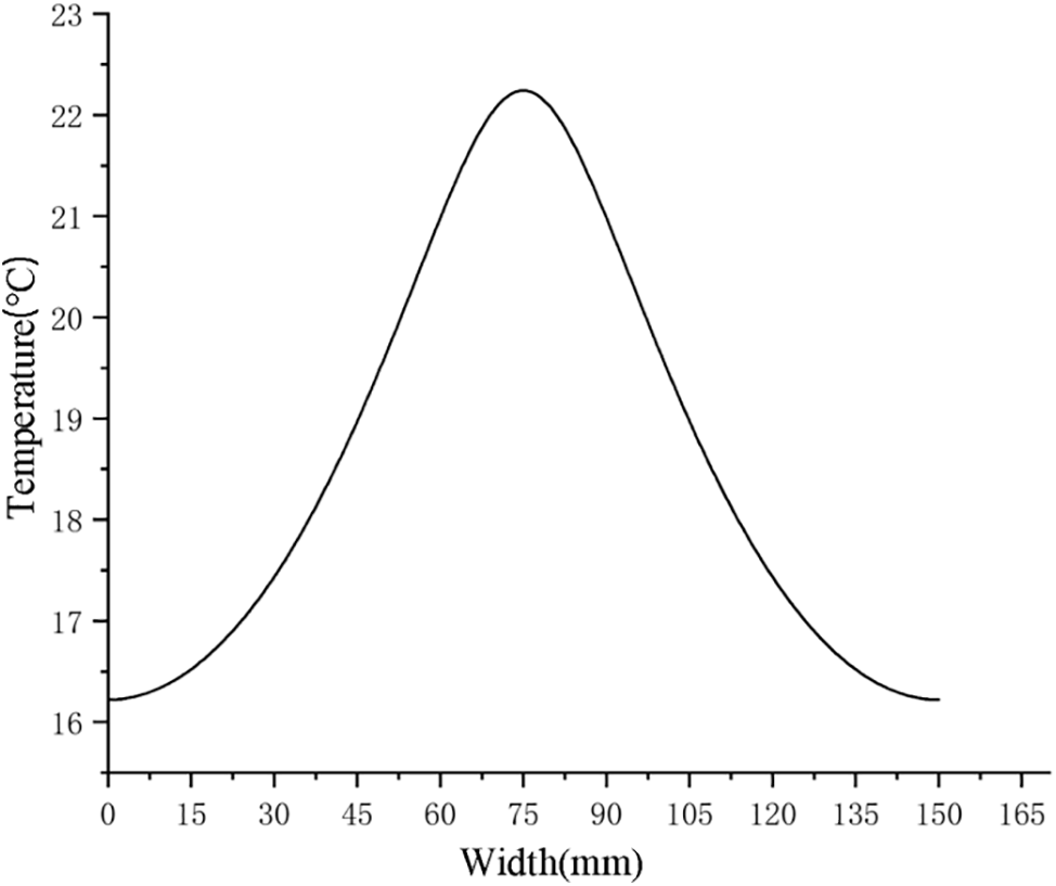
Figure 16: Temperature distribution across the floor surface
In this study, a novel structure of heating cable with finned aluminum sheath is proposed. The heat transfer characteristics of heating cables are investigated by constructing a 2D FEM. The main conclusions are as follows:
1. The number of fins on the sheath affects the heat transfer efficiency. The more fins, the faster the thermal system reaches thermal equilibrium.
2. The design of rectangular fins has larger surface areas than the triangular fins for the same volume of the sheath. Therefore, rectangular fins are more conducive to heat dissipation under natural convection conditions.
3. The triangular fins have a good heating effect on the floor, which is validated with experimental results. Under the initial temperature of 5°C, the maximum temperature on the floor surface rises to 22.5°C within only 2 h.
In this study, the indoor heating with one heating cable is investigated. In the future, a three-dimensional thermal model for the whole floor will be established. Due to the uniformity of floor temperature along the width direction, the pavement style and depth of the heating cables need to be carefully considered. The finned sheath can perform better in forced convection environments, numerical and experimental studies will also be done to further improve the heat transfer efficiency of this newly designed heating cable.
Acknowledgement: The authors would like to express sincere gratitude to Zhejiang Yuantong Cable Manufacturing Company for their technical support. Besides, the authors would thank Wenwen Jiang and Jinni Lu for their contributions to the FE simulation.
Funding Statement: The authors received no specific funding for this study.
Author Contributions: The authors confirm their contribution to the paper as follows: study conception and design: Wei Zhou, Weigang Li, Jixin Xu, Donghui Wen; data collection: Huichuang Yang, Yanmin Zhang. Analysis and interpretation of results: Lihui Zhang; draft manuscript preparation: Lihui Zhang, Huichuang Yang. All authors reviewed the results and approved the final version of the manuscript.
Availability of Data and Materials: Data will be made available on request.
Ethics Approval: Not applicable.
Conflicts of Interest: The authors declare that they have no conflicts of interest to report regarding the present study.
References
1. Su C, Hatef M, Bjrn P. Heating solutions for residential buildings in China: current status and future outlook. Energy Convers Manag. 2018;177:493–510. doi:10.1016/j.enconman.2018.10.005. [Google Scholar] [CrossRef]
2. Wu ZX, Hong NN, Ni Y, Gao L, Liu JP. Development status of domestic and foreign heating cable. Wire Cable. 2023;3:24–9 (In Chinese). [Google Scholar]
3. Mohammed AG, Ozgur G, Sevkat E. Electrical resistance heating for deicing and snow melting applications: experimental study. Cold Regions Sci Technol. 2019;160:128–38. doi:10.1016/j.coldregions.2019.02.004. [Google Scholar] [CrossRef]
4. Pei YY, Luo ZY, Xiao HL, Chen Z, Zhou XL, Yang ZY. A simple carbon fiber heating wire design method for preventing ice accretion on stay cables. Case Stud Therm Eng. 2022;34:101996. doi:10.1016/j.csite.2022.101996. [Google Scholar] [CrossRef]
5. Kong XF, Chang YF, Fan M, Li H. Analysis on the thermal performance of low-temperature radiant floor coupled with intermittent stratum ventilation (LTR-ISV) for space heating. Energy Build. 2023;278:112623. doi:10.1016/j.enbuild.2022.112623 [Google Scholar] [PubMed] [CrossRef]
6. Lai JX, Qiu JL, Fan HB, Chen JX, Xie YL. Freeze-proof method and test verification of a cold region tunnel employing electric heat tracing. Tunnelling Undergr Space. 2016;60:56–65. doi:10.1016/j.tust.2016.08.002. [Google Scholar] [CrossRef]
7. Xiao H, Jin G, Chu W. Residential space-heating energy demand in urban Southern China: an assessment for 2030. Energy Build. 2021;254:111598. [Google Scholar]
8. Zhang L, Zhang XM, Zhong XC, Song P. Thermal-mechanical coupling propagation and transient thermal fracture in multilayer coatings. Heat Transf Res. 2017;48:935–54. doi:10.1615/HeatTransRes.v48.i10. [Google Scholar] [CrossRef]
9. Yang ZY, Zhang JC, Xiao HL, Chen Z, Bao T, Liu Y. Assessment of the mechanical properties of carbon-fiber heating cables in snow and ice melting applications. Fluid Dyn Mater Process. 2023;19(9):2267–88. doi:10.32604/fdmp.2023.028652. [Google Scholar] [CrossRef]
10. Su X, Lai Y, Liu Y, Ma D, Wang P. Research of deicing and melting snow on airport asphalt pavement by carbon fiber heating wire. Adv Mater Sci Eng. 2020;2020(1):1–6. [Google Scholar]
11. Danilovic DS, Maricic VDK, Cokorilo AVB. Solving paraffin deposition problem in tubing by heating cable application. Therm Sci. 2010;14:247–53. doi:10.2298/TSCI1001247D. [Google Scholar] [CrossRef]
12. Tan YP, Zhu YT, Xiao HL. Model experimental study of carbon fiber heating wire for deicing and snow melting on a bridge deck. Adv Civil Eng. 2020;2020(1):1–15. [Google Scholar]
13. Liu J, Wang YW, Jia ZK, Liu JH, Hou YQ. Design of an electric heating system for Winter Olympic Village in Zhangjiakou district. Heat Vent Air Condition. 2022;52:94–8 (In Chinese). [Google Scholar]
14. Werner-Juszczuk AJ. Experimental and numerical investigation of lightweight floor heating with metallised polyethylene radiant sheet. Energy Build. 2018;177:23–32. doi:10.1016/j.enbuild.2018.08.011. [Google Scholar] [CrossRef]
15. Zhu XY, Zhang QF, Zhao D, Wu HT, Sun YT. Snow-melting pavement design strategy with electric cable heating system balancing snow melting, energy conservation, and mechanical performance. Resour Conserv Recycl. 2022;177:105970. doi:10.1016/j.resconrec.2021.105970. [Google Scholar] [CrossRef]
16. Zhao HB, Dai JJ, Wu K, Kong FH. Experimental and modeling analysis of thermal characteristics in carbon fiber wires. Heat Transf. 2020;49:1863–76. doi:10.1002/htj.v49.4. [Google Scholar] [CrossRef]
17. Jung BY, Je SM, Lee HG, Kim HS, Park JY, Oh BY, et al. Enhanced anti-freezing heating cable standard for fire prevention. Fire. 2022;5(6):216. doi:10.3390/fire5060216. [Google Scholar] [CrossRef]
18. Zhang HT, Lin SD. Research progress with membrane shielding materials for electro-magneti-c/radiation contamination. Membranes. 2023;13(3):315. doi:10.3390/membranes13030315 [Google Scholar] [PubMed] [CrossRef]
19. Mousavi Ajarostaghi SS, Zaboli M, Javadi H, Badenes B, Urchueguia JF. A review of recent passive heat transfer enhancement methods. Energies. 2022;15:986. doi:10.3390/en15030986. [Google Scholar] [CrossRef]
20. Sadeghianjahromi A, Wang CC. Heat transfer enhancement in fin-and-tube heat exchangers-a review on different mechanisms. Renew Sustain Energy Rev. 2021;137:110470. doi:10.1016/j.rser.2020.110470. [Google Scholar] [CrossRef]
21. Rezk K, Abdelrahman M, Attia A, Emam M. Thermal control of temperature-sensitive electronic components using a vapor chamber integrated with a straight fins heat sink: an experimental investigation. Appl Ther Eng. 2022;217:119147. doi:10.1016/j.applthermaleng.2022.119147. [Google Scholar] [CrossRef]
22. Hekmat S, Tavana P, Molaeimanesh GR. A novel compact battery thermal management system comprising phase change material, mini-channels, and fins suitable for EV battery packs. J Energy Storage. 2024;82:110392. doi:10.1016/j.est.2023.110392. [Google Scholar] [CrossRef]
23. Weng JW, Ouyang DX, Yang XQ, Chen MY, Zhang GQ, Wang J. Optimization of the internal fin in a phase-change-material module for battery thermal management. Appl Therm Eng. 2019;167:114698. [Google Scholar]
24. Zhang FR, Lu F, Liang BB, Zhu YL, Huan G, Kang X, et al. Thermal performance analysis of a new type of branch-fin enhanced battery thermal management PCM module. Renew Energy. 2023;206(203):1049–63. doi:10.1016/j.renene.2023.02.083. [Google Scholar] [CrossRef]
25. Xu JC, Fang HF, Wang MQ, Li X, Chen YJ. Simulation research on thermal management system of battery module with fin heat dissipation structure. Appl Therm Eng. 2024;239:122177. doi:10.1016/j.applthermaleng.2023.122177. [Google Scholar] [CrossRef]
26. He ZX, Yu QH, Ye JD, Yan FW. Optimization of plate-fin heat exchanger performance for heat dissipation of thermoelectric cooler. Case Stud Therm Eng. 2024;53:103953. doi:10.1016/j.csite.2023.103953. [Google Scholar] [CrossRef]
27. Liu J, Zhao B, Xie YM. Analysis of the effect of fin spacing on the performance of tube-fin radiators. Mech Des Manuf. 2020;11:82–5 (In Chinese). [Google Scholar]
28. Yang WJ, Wang H, Cong PW, Zhou XY, Xu YM. Structural optimization of finned tube heat exchanger. Metal Heat Treat. 2017;42:208–11 (In Chinese). [Google Scholar]
29. Tao WQ, Yang SM. Heat transfer. Xi’an, China: Xi’an Jiaotong University Press, Higher Education Press; 2006 (In Chinese). [Google Scholar]
30. Gupta A, Kumar N, Sachdeva A. Factors affecting the ageing of polymer composite: a state of art. Polym Degrad Stab. 2024;221:110670. doi:10.1016/j.polymdegradstab.2024.110670. [Google Scholar] [CrossRef]
31. Yang YX, Wang ZJ, Zhou FZ, Liu C, Duanmu L, Zhai YC, et al. Comparison of indoor thermal environments and human thermal responses in Northern and Southern China during winter. J Build Eng. 2024;82:108131. doi:10.1016/j.jobe.2023.108131. [Google Scholar] [CrossRef]
Cite This Article
 Copyright © 2024 The Author(s). Published by Tech Science Press.
This work is licensed under a Creative Commons Attribution 4.0 International License , which permits unrestricted use, distribution, and reproduction in any medium, provided the original work is properly cited.


 Submit a Paper
 Propose a Special lssue
 View Full Text
 Download PDF
 Downloads
 Citation Tools