
 Submit a Paper
 Propose a Special lssue
 Open Access
ARTICLE

Optimization of Finned-Tube Heat Exchanger in a Gravity-Assisted Separated Heat Pipe
1 Huadong Engineering Corporation Limited, Power Construction Corporation of China, Hangzhou, 310014, China
2 Institute of Refrigeration and Cryogenics, Zhejiang University, Hangzhou, 310027, China
* Corresponding Author: Shaozhi Zhang. Email:
(This article belongs to the Special Issue: Computational and Numerical Advances in Heat Transfer: Models and Methods II)
Frontiers in Heat and Mass Transfer 2024, 22(4), 1209-1229. https://doi.org/10.32604/fhmt.2024.052415
Received 01 April 2024; Accepted 06 June 2024; Issue published 30 August 2024
 View Full Text
 Download PDF
Abstract
Finned-tube heat exchanger (FTHE) is often used as an evaporator in commercial products of separated heat pipe (SHP). The working conditions of FTHE in gravity-assisted SHP are significantly different from those working in refrigerators and air conditioners. Although FTHE is widely used in commercial products of SHP, previous research on its characteristics is very limited. In this paper, a mathematical model for a SHP with FTHE as the evaporator and plate heat exchanger as the condenser is established and verified with experiments. Parametric analyses are carried out to investigate the influences of evaporator design parameters: air inlet velocity, number of tube rows, tube diameter, and fin pitch. With the increasing of air velocity, number of tube rows and tube diameter, and the decreasing of fin pitch, the heat transfer rate increases, while the energy efficiency ratio (EER) decreases monotonically. Using the total cost of the ten-year life cycle as the performance index, the structure parameters of the evaporator with a given heat transfer rate are optimized by the method of orthogonal experimental design. It is found that the total cost can differ as large as nearly ten times between groups. Among the three factors investigated, the number of tube rows has a significant impact on the total cost of the evaporator. With more tube rows, the total cost will be less. The impacts of fin pitch and tube diameter are insignificant. These results are of practical importance for the engineering design of FTHE in gravity-assisted SHP.Keywords
Nomenclature
| Boiling number | |
| Cw | Specific heat capacity of water |
| Equivalent diameter | |
| D | Inner diameter of the tube |
| f | Friction coefficient |
| F | Enhancement factor of forced convection |
| Volume flow rate of air | |
| The maximum volume flow rate | |
| g | Gravity acceleration |
| Mass flux | |
| Outlet enthalpy of working fluid | |
| Inlet enthalpy of working fluid | |
| Outlet air enthalpy | |
| Inlet air enthalpy | |
| Vaporization heat | |
| Heat transfer coefficient at the point x = 90% | |
| Heat transfer coefficient of single-phase vapor | |
| Total heat transfer coefficient | |
| L | Length of the tube |
| Fin length along the air flow direction | |
| Length of the two-phase zone | |
| The mass of working fluid in the evaporator | |
| The mass of working fluid in the condenser | |
| The mass of working fluid in the riser | |
| The mass of working fluid in the downcomer | |
| Flowrate of the working fluid | |
| Flowrate of air | |
| M | Molecular weight |
| Nu | Nusselt number |
| Pr | Prandtl number |
| Pressure of working fluid | |
| Critical pressure of working fluid | |
| q | Heat flux |
| Effective heat flux | |
| Q | Heat transfer rate |
| Re | Reynolds number |
| Reynolds number of liquid phase | |
| S | Suppression factor of forced convection |
| Two | Temperature of return water |
| Twi | Temperature of inlet water |
| Average air temperature at the evaporator inlet | |
| u | Velocity |
| Air velocity at the narrowest section | |
| Velocity of working fluid | |
| vw | Water flow rate |
| Internal volume of the evaporator | |
| The liquid volume of filled working fluid | |
| Fan power | |
| x | Quality of the working fluid |
| Martinelli parameter | |
| Void fraction | |
| Filling ratio | |
| Fan efficiency | |
| Condensation heat transfer coefficient | |
| ρw | Water density |
| Density of liquid | |
| Density of vapor | |
| Density of working fluid | |
| Density of saturated gas | |
| Heat transfer area of the segment | |
| Acceleration pressure drop | |
| ΔPevap | Evaporator pressure drop |
| ΔPv | Riser pressure drop |
| ΔPcond | Condenser pressure drop |
| ΔPl | Downcomer pressure drop |
| Friction pressure drop | |
| Gravity pressure drop | |
| Maximum operating pressure lift | |
| Heat exchanged | |
| Temperature difference between cold and hot sources | |
| Dynamic viscosity of saturated liquid | |
| Dynamic viscosity of saturated gas | |
| Heat conductivity of liquid working fluid | |
| Thermal resistance of the system |
The data center is becoming a usual and necessary facility in many countries all over the world. For a typical data center, the electricity consumption of traditional cooling may possess 38% of the total consumption [1]. To alleviate the pressure of increasing energy requirements imposed by data centers, many kinds of free cooling technologies have been put forward [2,3]. Among these technologies, separated heat pipe (SHP), or loop thermosyphon has been a hot topic during recent years [4,5]. Many fundamental studies about heat and flow of SHP were carried out. Tang et al. studied the flow and heat transfer characteristics of an SHP in which the evaporator and the condenser consisted of 5-tube-banks [6]. Ding et al. did visualization experiments on boiling heat transfer and flow characteristics of R134a and R22 in a tube-in-tube evaporator [7]. Further studies by the same group focused on the relationship between mass flow and boiling heat transfer of R134a at different filling ratios [8]. Zhang et al. investigated the startup of loop thermosyphon with multiple evaporators and found the oscillation interaction between two adjacent evaporators [9]. Louahlia-Gualous et al. conducted experimental investigations on a loop thermosyphon using water as a working fluid and proposed new correlations for evaporation and condensation heat transfer coefficients [10]. In their study, the condenser consists of two coaxial copper tubes and the evaporator consists of liquid and vapor chambers and a mini-channel layer.
Besides fundamental studies, more studies were about the application of loop thermosyphon in data centers. Ling et al. built a steady-state mathematical model for a micro-channel separate heat pipe, validated it with experimental data from an enthalpy difference laboratory, and analyzed the effects of geometrical design and environment conditions [11]. Zhang et al. investigated a CO2 loop thermosyphon with a microchannel parallel-flow evaporator and condenser with the help of thermal imaging and optimized the filling ratio with a distributed-parameter model [12]. In their further studies, the performance of CO2 is compared with traditional working fluids R22 and R134a, and the effects of some key geometric parameters were evaluated [13]. Tong et al. studied the self-regulating performance of a loop thermosyphon with two evaporators and CO2 as the working fluid under uniform and nonuniform heating conditions and found that the self-regulating ability of the loop thermosyphon is very limited [14]. Nadjahi et al. presented an analytical model for a loop thermosyphon with a mini-channel parallel-flow evaporator and finned-tubes condenser and identified the most influencing parameters for the cooling capacity [15]. Zhang et al. found that a separate heat pipe with a partially liquid-filled downcomer can maintain 95% of its maximum heat transfer capacity in a wide range of working fluid charges by the establishment of a numerical model, and the lower limit of the range is related to vapor quality at evaporator exit and the upper limit is related to liquid column height in the downcomer [16]. To meet increased cooling requirements, a multi-row heat exchanger instead of a single-row heat exchanger seems more beneficial. Xia et al. proposed a distributed parameter model that reflects the effects of non-uniform distributed refrigerant flow and the interaction of air among rows and verified it by experiment. It was found that the increment of heat transfer capacity by adding a row will be less than 2% when the number of tube rows is larger than 5 [17].
To improve the performance of traditional SHP, some new ideas were proposed. Zhu et al. introduced a separator in the loop to ensure that only vapor fluid enters the condenser and proved that the separator-assisted two-phase thermosyphon loop can achieve a better performance than the basic two-phase thermosyphon loop [18]. Zhu et al. introduced the simulation module of a separate heat pipe heat exchanger in the building energy simulation tool DeST and demonstrated its engineering applications. The heat transfer performance and the energy consumption characteristic were described by a grey-box model [19]. Wang et al. investigated the combination of evaporative condensation and microchannel in a separated heat pipe system about its energy-saving potential and found that the new system could save 62.04% of the energy used annually compared to the standard cooling system [20].
The finned-tube heat exchanger (FTHE) is often used as an evaporator in commercial products of gravity-assisted SHP, and yet there are very few studies about its performance and improvement, as can be seen from Table 1 in which the type of evaporator employed in SHP in recent literature is listed. Chen et al. did experiments on a heat-pipe backplane using FTHE as an evaporator and found that the cooling capacity was improved when the diameter of the copper tube in the heat exchanger was reduced from 7 to 5 mm [21].

Currently, FTHE is also widely used in refrigerators and air conditioners. Stewart et al. examined finned-tube condenser heat exchangers used in residential air conditioning systems to find an optimum design under constraints of material cost, aspect ratio, and frontal area [22]. Kim et al. investigated the JF factor by varying the number of passes and the inlet diameter so that the optimal number of passes for a fixed size of heat exchanger could be determined [23]. Geb et al. made a ten-parameter optimization of FTHE with a genetic algorithm optimizer by fast solving volume-averaged conservation equations of mass, momentum, and energy [24]. Zhang et al. developed a numerical model to determine the performance of FTHE in a low-pressure environment and investigated the impacts of air pressure on the air-side heat transfer coefficient [25]. Macchitella et al. reviewed the modeling and optimization methods for plate-finned tube heat exchangers used in refrigeration and gave a focus on circuitry configurations [26]. The working conditions of finned-tube heat exchangers in refrigerators and air conditioners are very different from those working in gravity-assisted separated heat pipes, especially over the mass flux of working fluid. Therefore, the optimization results of FTHE for the former cannot apply to the former.
To fill the gap of FTHE optimization used as an SHP evaporator in the data center, experimental and theoretical investigations on a gravity-assisted SHP that employs FTHE as the evaporator and plate heat exchanger as the condenser are presented in this study. Firstly, the experiment is described, followed by the introduction of the mathematical model. The model for the SHP is validated by the experimental data. Then the impacts of design parameters on FTHE performance and the optimization of FTHE under certain constraints are carried out and discussed. Finally, the conclusions for the optimization are drawn.
The schematic diagram of the setup for the experimental study of a SHP is shown in Fig. 1. R134a is used as the working fluid of the SHP. The evaporator of the SHP is an FTHE which acts as a backplane panel of a cabinet. The condenser of the SHP is a water-cooled plate heat exchanger. The height difference between the top of the evaporator and the bottom of the condenser is 2.6 m. The size information of the SHP is given in Table 2. The cabinet is placed in an air-conditioned room. The simulated loads in the cabinet are four electric heaters. The power of each heater is 2 kW. The cooled water is supplied by a small water-cooled chiller. The fan of the cooling tower is driven by an inverter.
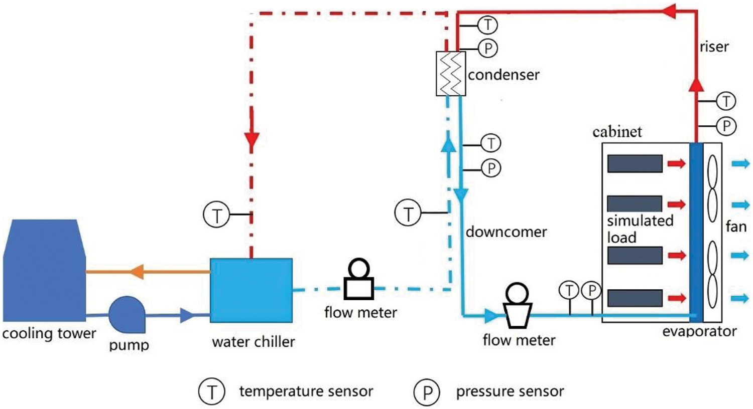
Figure 1: Schematic diagram of the experimental setup

The information on the sensors is given in Table 3. The sensors are connected to a data acquisition unit, Agilent 34970a. The software accompanied by the instrument, BenchLink Data Logger, is used to collect the experimental data.

The water side parameters are used to calculate the heat transfer rate:
The thermal resistance of the system is defined as:
Because the driving force of the SHP relies on gravity, the power consumption of the SHP only comes from the axial fans of the evaporator. Thus, the energy efficiency ratio of the SHP is calculated by [27]:
The experimental uncertainty mainly comes from the errors of measurement equipment. The uncertainties are calculated with the method suggested by Ding et al. [28]. The maximum uncertainties for the heat transfer rate, the thermal conductivity, and the EER are 2.81%, 2.96%, and 2.98%, respectively.
3 Model for a Gravity-Assisted Separated Heat Pipe
The schematic of a SHP with FTHE as the evaporator and plate heat exchanger as the condenser is shown in Fig. 2. To analyze the cooling performance of the SHP, a steady-state thermal and hydraulic model is established. The following assumptions are made to develop this model: (1) the working fluid is uniformly distributed in all the parallel tubes on the same row of the evaporator, and the fluid flow is one-dimensional in the evaporator; (2) the riser and downcomer have no heat exchange with the environment, or they are adiabatic; (3) the airflow through the evaporator is uniform; (4) the pressure drops in the manifolds of both the evaporator and condenser are neglected; (5) the pressure drops in the riser and downcomer due to flow turn are neglected; (6) the downcomer is filled with liquid.
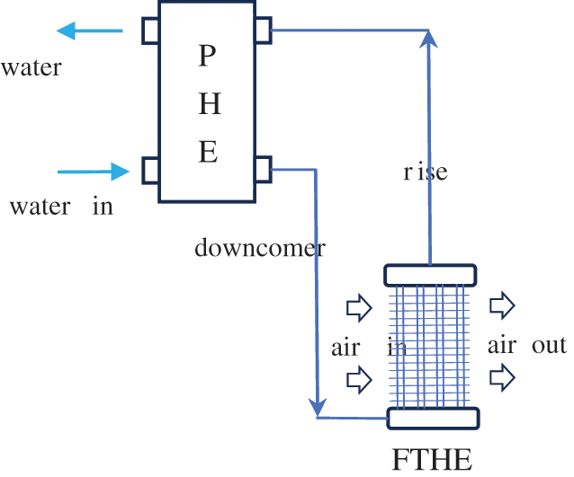
Figure 2: Schematic diagram of a SHP with FTHE as the evaporator and plate heat exchanger as the condenser
The mass flow rate of working fluid in the loop is determined by the equation of pressure drop as:
3.1.1 Pressure Drop in the Evaporator
The evaporator may be divided into three zones according to the state of the working fluid: subcooled zone, two-phase zone and superheated zone. In the subcooled and superheated zones, the pressure drop may be calculated by:
where
where
In the two-phase zone, the pressure drop may be calculated by:
where
in which subscript out denotes the outlet of the zone, subscript in denotes the inlet of the zone,
3.1.2 Pressure Drop in the Condenser
The condenser may be divided into three zones according to the state of the working fluid: superheated zone, two-phase zone and subcooled zone. In superheated zone or subcooled zone, the pressure drop consists of two parts:
For single phase flow of gas or liquid in the superheated zone or subcooled zone, the correlation of friction coefficient proposed by Muley et al., which considers the effects of chevron angle and surface area enlargement factor, is adopted [31].
In the two-phase zone, the pressure drop may be calculated by:
where the gravity pressure drop
3.1.3 Pressure Drop in the Riser and Downcomer
The pressure drops in the riser and downcomer are calculated by:
where friction coefficient f is derived from Eqs. (5) or (6).
The air pressure drop through tube array with plain flat fins is calculated by a correlation provided in [33].
where constant A equals 0.0113 for rough surface.
The working fluid exchanges heat with cooling water in the condenser and with hot air in the evaporator. Energy conservation and heat transfer equations can be established for each segment of the two heat exchangers. As shown in Fig. 3, the evaporator is segmented in two dimensions, one along the flow direction of working fluid, and the other along the flow direction of air. As shown in Fig. 4, for one element (i, j) of the evaporator, the following equations can be established if NTU-efficiency method is employed [34]:
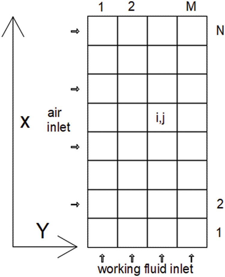
Figure 3: Segmentation of the evaporator

Figure 4: One element of the evaporator
3.2.1 Heat Transfer in the Evaporator
For single phase heat transfer of working fluid in the tube, different correlations, Hausen, Gnielinski, and Dittus-Boelter, are applied according to Renold number [35].
For evaporative heat transfer of working fluid, the Gungor et al. correlation is adopted as follows [36]:
For evaporative heat transfer where fluid quality is greater than 90%, a correlation suggested by [37] is employed:
A heat transfer coefficient correlation for plain flat fins on staggered tube bundles is adopted from [33] to calculate heat transfer coefficient of air side:
where m and C are functions of
3.2.2 Heat Transfer in the Condenser
For water, superheated gas or subcooled liquid of working fluid in plate heat exchanger, a correlation proposed by Roetzel et al. is adopted for single phase heat transfer calculation [38]:
For two-phase condensation of working fluid in plate heat exchanger, a correlation from a technical manual is used [39]:
Zivi model is employed to describe the relationship between void fraction and quality of working fluid [29]:
The total charge of working fluid consists of four parts as described below:
Filling ratio is defined as follows:
The fan model estimates the pressure lift with a quadratic curve:
The power consumption is calculated by:
where
To evaluate the comprehensive effect of the fan, the energy efficiency ratio (EER) of the heat pipe is defined as follows:
where Q is the heat exchanged by the evaporator.
All the fluid physical properties are obtained through calling the REFPROP (version 10.0) program of NIST [40].
When the configuration of the heat pipe (including the structure of the heat exchangers, the length and diameter of the riser and downcomer, the height difference between the evaporator and the condenser), the state parameters of the inlet fluids and the charge amount of working fluid in the heat pipe are known, the working state of the heat pipe may be determined by solving the above-listed equations which describe heat transfer, fluid flow, energy conservation and momentum conservation. The calculation procedure is shown in Fig. 5 and described briefly as follows: (1) input the known parameters; (2) assume the total flowrate of the working fluid, the inlet pressure and subcooling of the evaporator; (3) calculate the evaporator column by column the heat transfer and the fluid flow and adjust the flow distribution of working fluid between columns according to the balance of pressure drop; (4) calculate the riser, condenser and the downcomer; (5) compare the state parameters between downcomer outlet and evaporator inlet, the calculated working fluid charge and the given charge, and adjust the total flowrate, the inlet pressure and subcooling of the evaporator according to the comparison; (6) repeat (3) until convergence is reached; (7) output the calculation results, including outlet parameters of both heat exchangers, flowrate of working fluid, pressure drop on air side, heat transfer rate.

Figure 5: Flowchart of the calculation program
The performance of SHP is influenced by many factors. The exchanged heat depends on: (1) the inlet temperature and flowrate of the evaporator and the condenser; (2) the structure and area of the evaporator; (3) the structure and area of the condenser; (4) the installation height difference between the heat exchangers; (5) the internal diameter and the length of the riser and the downcomer; (6) the filling ratio of working fluid. The present work focuses on the optimization of the evaporator structure while the other factors are considered as follows: (1) the heat resistance will be used instead of the exchanged heat to eliminate the impacts of the inlet parameters; (2) the configuration of the condenser, the riser and the downcomer are fixed, taken from Table 2; (3) the filling ratio of working fluid will be optimized for each evaporator configuration; (4) the impact of the installation height difference on the optimization will be investigated.
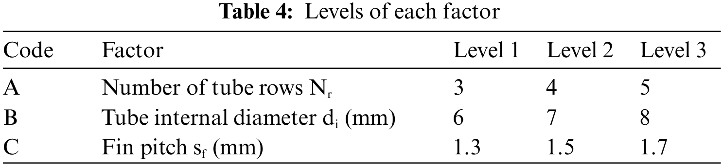
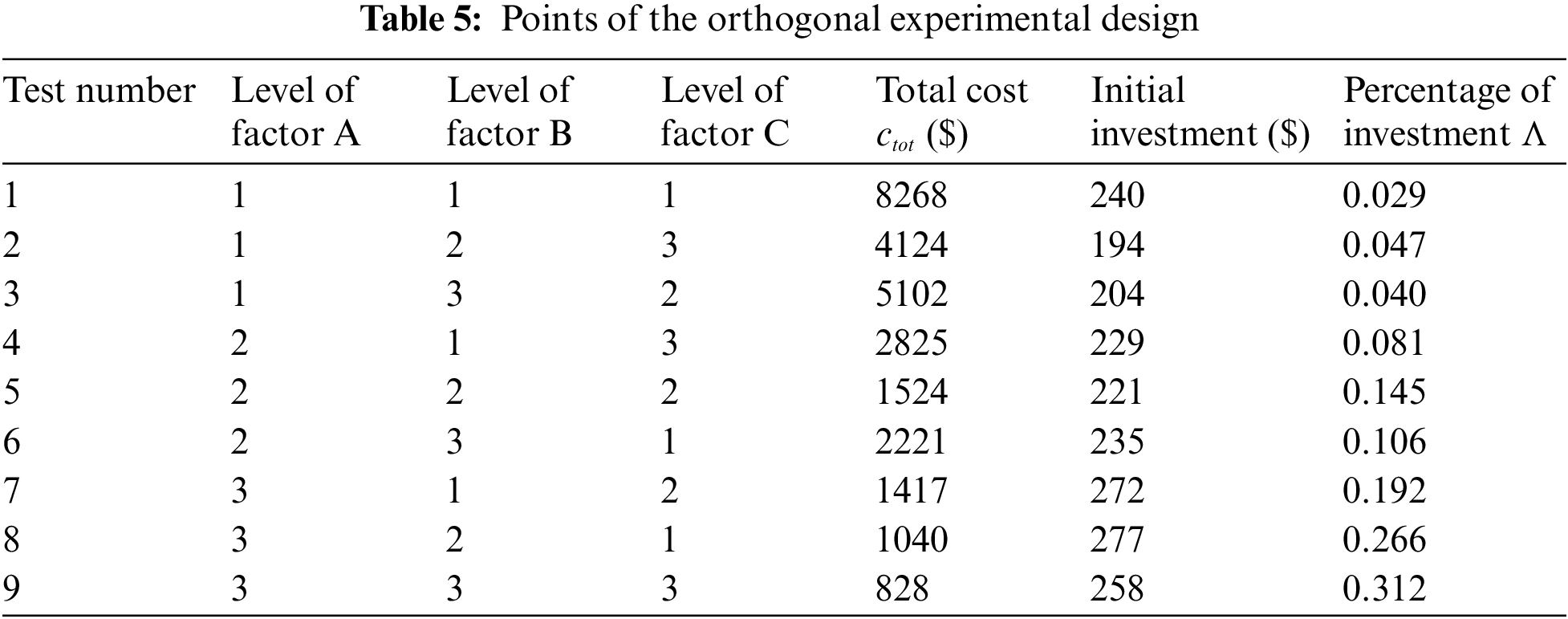
The structure parameter of the evaporator will be optimized by economic analysis with the method of orthogonal experimental design when the overall dimension of the evaporator is limited. Three factors are considered: tube internal diameter di, fin pitch sf, and number of tube rows Nr. The factors and their levels are listed in Table 4. An orthogonal experimental design L9(33) is done with the help of SPSSAU-Data Science Analysis Tool [41].
The total cost includes initial investment cost and electricity cost of the fan to flow the air over the finned tubes [42]:
where
Fig. 6 shows a comparison of Q, heat dissipated by the evaporator, between experimental and numerical results under different filling ratios, while the other conditions are as follows: air flow rate 3200 m3/h, water flow rate 1.34 ton/h, height difference between evaporator and condenser 0.6 m, water inlet temperature 20°C. The average discrepancy is 4.3%, and the maximum discrepancy is 10.7%. Fig. 7 shows a comparison of Q between experimental and numerical results under different water inlet temperatures, while the other conditions are as follows: air flow rate 3200 m3/h, water flow rate 1.34 ton/h, height difference between evaporator and condenser 0.6 m, filling ratio 97.1%. The average discrepancy is 3.6%, and the maximum discrepancy is 6.8%. From the comparisons, it can be inferred that the established model is consistent with the experiment.

Figure 6: Comparison of heat transfer rate vs. filling ratio between test and simulation

Figure 7: Comparison of heat transfer rate vs. water inlet temperature between test and simulation
With the established model and code, parametric analyses are carried out to investigate the influences of different design parameters of the evaporator.
As air inlet velocity increases, heat transfer will be enhanced, meanwhile, air pressure dop and fan power will increase. Fig. 8 gives the impact of air inlet velocity on heat transfer rate and EER under the following conditions: water flow rate 1.34 ton/h, height difference between evaporator and condenser 0.6 m, filling ratio 97.1%, water inlet temperature 16°C, air inlet temperature 35°C. The heat transfer rate increases monotonically with air velocity, while EER decreases monotonically with air velocity. As air velocity increases from 1.0 to 3.5 m/s, the heat transfer rate will improve by 83.1%, while EER will reduce to 21.7%. The variation amplitude of EER is much larger than that of heat transfer rate because air pressure drop and air flow rate is more influenced by air velocity than heat transfer coefficient. For the operation of the heat pipe, the EER-heat transfer rate relationship obtained implies that lowering fan speed at low load of heat dissipation can greatly improve EER.
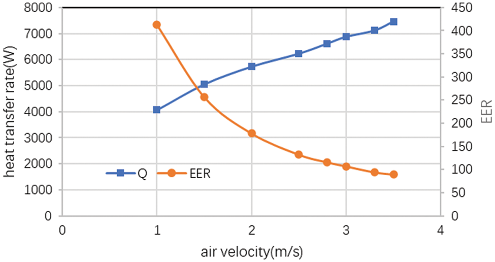
Figure 8: Impact of air inlet velocity on heat transfer rate and EER
As the number of tube rows along the air path increases, the heat exchange area will increase, but the temperature difference between hot air and cold fluid will decrease, and the marginal benefit of row addition will decrease. On the other hand, the total mass flow rate of working fluid will change to a small extent with the number of tube rows, thus the mass flux of working fluid will be inversely proportional to the number of tube rows. However, for very low mass flux (≤20 kg/m2s) of working fluid in a vertical tube, the variation of the evaporative heat transfer coefficient with mass flux is very limited, let alone the total heat transfer coefficient of the evaporator. The comprehensive influence of the number of tube rows may be evaluated by simulation. Fig. 9 demonstrates the impact of the number of tube rows on capacity and EER under the following conditions: water flow rate 1.34 ton/h, height difference between evaporator and condenser 0.6 m, water inlet temperature 16°C, air inlet temperature 35°C. When the number of tube rows changes from 2 to 6, the heat transfer rate will increase by 94.0% because more heat transfer area is available, while EER will decrease by 35.3% because the increased amplitude of air pressure drop is larger than that of heat transfer coefficient. For number of tube rows 5 and 6, their EERs are almost the same.

Figure 9: Impact of number of tube rows on heat transfer rate and EER
The flow area of working fluid is proportional to the square of internal tube diameter. As internal tube diameter increases, the flow area of working fluid will increase, thus leading to lower flow resistance and higher flow rate. At the same time, the working fluid mass flux may decrease. Fig. 10 shows the comprehensive impact of tube diameter on heat transfer rate and EER under the following conditions: water flow rate 1.34 ton/h, height difference between evaporator and condenser 0.6 m, water inlet temperature 16°C, air inlet temperature 35°C. As the tube diameter increases from 6 to 9 mm, the heat transfer rate will improve by 22.4%, and EER will decrease by 18.1%. The increase of heat transfer rate may be due to the decreased flow resistance on working fluid side. The decrease of EER is due to the increased pressure drop on air side.

Figure 10: Impact of tube diameter on heat transfer rate and EER
The fin pitch will influence the performance of FTHE in two aspects. One is the pressure drop of air side, or the power consumption of the fans. The other is the fin efficiency. Fig. 11 shows the impact of fin pitch on heat transfer rate and EER under the following conditions: water flow rate 1.34 ton/h, height difference between evaporator and condenser 0.6 m, water inlet temperature 16°C, air inlet temperature 35°C. As the fin pitch increases from 1.2 to 1.8 mm, the heat transfer rate will decrease by 9.4% because the heat transfer area is reduced, however, EER will increase by 35.0% because pressure drop on air side decreases at a larger amplitude.

Figure 11: Impact of fin pitch on heat transfer rate and EER
The nine experimental points obtained from the orthogonal experimental design are shown in Table 5. It is noted that the total cost can be differed as large as nearly tenfold between test 1 and test 9. For all tests, the major part of the total cost is the operation or electricity cost. To obtain the minimum total cost, the optimal condition is A3B3C3. An analysis of variance (ANOVA) is performed to show that factor A, number of tube rows, has a significant impact (P = 0.036), while factor B and C have insignificant impacts (P = 0.183, 0.319).
FTHE has many design parameters which make its optimization complicated. Two methods are adopted to fulfil the task: optimization algorithm and design of experiment (DOE). For the former, genetic algorithm and simplex algorithm are often employed. Stewart et al. developed a system model with great detail in the condenser component for an 8.8 kW vapor compression, residential air conditioner to optimize the finned-tube condenser [22]. Ten different design parameters were searched with the simplex algorithm. They found that for a fixed frontal area, the smallest tube gives the best results, leading to benefits of decrease in the air-side form drag caused by the tubes, increase in the heat transfer coefficients due to a smaller hydraulic diameter and less refrigerant charge in the tubes. Sepehr et al. designed an FTHE used for heat recovery with genetic algorithm [42]. Six parameters (pipe diameter, pipe length, number of pipes per row, number of rows, fin pitch, and fin length ratio) were optimized for the least total cost and the highest effectiveness. Geb et al. optimized an FTHE used for air cooling/heating with water with genetic algorithm [24]. 10-dimensional space was searched for the highest effectiveness. As for the latter, orthogonal experimental design, Taguchi method and response surface method are often employed. Geb et al. applied Taguchi method to investigate the influences of seven geometric parameters on the overall thermal-hydraulic performance of a H-type FTHE [24]. The intuitive analysis and analysis of variance were used to determine the important parameters. Here in our study, orthogonal experimental design is adopted for the optimization of an FTHE used as evaporator in a loop heat pipe. From the analysis results, it can be inferred that the method is appropriate for the optimization task.
Very few studies have been involved with FTHE used as evaporator in a loop heat pipe. Existing studies focused on FTHE in refrigerators and air conditioners. Chen et al. studied a heat pipe backplane air-conditioning system coupled with an indirect–direct evaporative cooling chiller and compared the experimental results obtained with 5 and 7 mm diameter copper tubes. They found that smaller tube increases the flow area of the air and decreases the resistance, thus leading to air flowrate increment of about 16% and capacity increment of 12.46% [21]. Their study emphasized the importance of the flow resistance of the air side. FTHE in gravity-assisted SHP is different from those in refrigerators and air conditioners, having much lower mass flux of working fluid. Nevertheless, from our study, similar logistics may be noted about the importance of air-side pressure drop. The optimized configuration adopts the largest fin pitch.
A mathematical model for a gravity-assisted SHP with FTHE as the evaporator and plate heat exchanger as the condenser is established and compared with experiments. Parametric analyses and optimization work are carried out. The findings can be summarized as follows:
1) The average deviation of the calculated heat transfer rate from the experimental data is 4.3%. The mathematical model is validated.
2) Within the investigated ranges, i.e., air inlet velocity 1.0 to 3.5 m/s, number of tube rows 2 to 6, tube diameter 6 to 9 mm, and fin pitch 1 to 2 mm, the heat transfer rate and EER changes monotonically with the factors. When air velocity, the number of tube rows, and tube diameter increase and fin pitch decreases, the capacity increases, but EER decreases.
3) The number of tube rows of the evaporator has the largest impact on its total cost of the ten-year life cycle, and the impacts of fin pitch and tube diameter are insignificant. To minimize the total cost for the presented case in this study, the optimal parameters are listed as follows: number of tube rows 5, tube diameter 8 mm, fin pitch 1.7 mm.
These findings can help to improve the design of FTHE which is used in gravity-assisted SHP.
Acknowledgement: The authors would like to thank Chen Guangming and Tang Liming for their suggestions on the experiment.
Funding Statement: This work was supported by Archaeological Artifact Protection Technology Project of Zhejiang Province (NO2021013).
Author Contributions: Study conception and design: Shaozhi Zhang, Yiming Rongyang; experiment: Bowen Du, Shuai Wang; analysis and interpretation of results: Weitao Su, Shaozhi Zhang; draft manuscript preparation: Yiming Rongyang, Shaozhi Zhang, Jianjian Wei. All authors reviewed the results and approved the final version of the manuscript.
Availability of Data and Materials: The data are available from the corresponding author upon reasonable request.
Conflicts of Interest: The authors declare that they have no conflicts of interest to report regarding the present study.
References
1. Habibi KA, Halgamuge SK. A review on efficient thermal management of air-and liquid-cooled data centers: from chip to the cooling system. Appl Energ. 2017;205:1165–88. [Google Scholar]
2. Xu S, Zhang H, Wang Z. Thermal management and energy consumption in air, liquid, and free cooling systems for data centers: a review. Energies. 2023;16(3):1279. [Google Scholar]
3. Alkrush AA, Salem MS, Abdelrehim O, Hegazi AA. Data centers cooling: a critical review of techniques, challenges, and energy saving solutions. Int J Refrig. 2024;160:246–62. [Google Scholar]
4. Zhang H, Shao S, Tian C, Zhang K. A review on thermosyphon and its integrated system with vapor compression for free cooling of data centers. Renew Sust Energ Rev. 2018;81:789–98. [Google Scholar]
5. Wang X, Wen Q, Yang J, Xiang J, Wang Z, Weng C, et al. A review on data center cooling system using heat pipe technology. Sustain Comput-Infor. 2022;35:100774. [Google Scholar]
6. Tang Z, Liu A, Jiang Z. Two phase flow and heat transfer characteristics of a separate-type heat pipe. Heat Mass Transfer. 2011;47(7):841–6. [Google Scholar]
7. Ding T, Cao HW, He ZG, Li Z. Visualization experiment on boiling heat transfer and flow characteristics in separated heat pipe system. Exp Therm Fluid Sci. 2018;91:423–31. [Google Scholar]
8. Ding T, Cao H, He Z, Li Z. Experimental investigations of the influence factors for the boiling heat transfer characteristics of R134a coolant in a loop thermosiphon system. Int J Refrig. 2020;115:182–90. [Google Scholar]
9. Zhang H, Shao S, Xu H, Tian C. Experimental investigation on a loop thermosyphon with three evaporators: unique startup and oscillation phenomena. Int J Refrig. 2019;99:363–70. [Google Scholar]
10. Louahlia-Gualous H, Le Masson S, Chahed A. An experimental study of evaporation and condensation heat transfer coefficients for looped thermosyphon. Appl Therm Eng. 2017;110:931–40. [Google Scholar]
11. Ling L, Zhang Q, Yu Y, Wu Y, Liao S. Study on thermal performance of micro-channel separate heat pipe for telecommunication stations: experiment and simulation. Int J Refrig. 2015;59:198–209. [Google Scholar]
12. Zhang H, Shi Z, Liu K, Shao S, Jin T, Tian C. Experimental and numerical investigation on a CO2 loop thermosyphon for free cooling of data centers. Appl Therm Eng. 2017;111:1083–90. [Google Scholar]
13. Zhang H, Shao S, Jin T, Tian C. Numerical investigation of a CO2 loop thermosyphon in an integrated air conditioning system for free cooling of data centers. Appl Therm Eng. 2017;126:1134–40. [Google Scholar]
14. Tong Z, Liu X, Jiang Y. Experimental study of the self-regulating performance of an R744 two-phase thermosyphon loop. Appl Therm Eng. 2017;186:1–12. [Google Scholar]
15. Nadjahi C, Louahlia-Gualous H, Le Masson S. Experimental study and analytical modeling of thermosyphon loop for cooling data center racks. Heat Mass Transfer. 2020;56(1):121–42. [Google Scholar]
16. Zhang J, Song G, Qiu Z, Li H. Thermal analysis and effects study of evaporator exit vapor quality in a separate heat pipe. Appl Therm Eng. 2020;181:115716. [Google Scholar]
17. Xia G, Zhuang D, Ding G, Lu J, Han W, Qi H. A distributed parameter model for multi-row separated heat pipe with micro-channel heat exchangers. Appl Therm Eng. 2021;182:116113. doi:10.1016/j.applthermaleng.2020.116113. [Google Scholar] [CrossRef]
18. Zhu L, Yu J. Performance analysis of a separator assisted two-phase thermosyphon based on an experimentally validated model. Appl Therm Eng. 2017;125:532–45. doi:10.1016/j.applthermaleng.2017.07.050. [Google Scholar] [CrossRef]
19. Zhu D, Yan D, Li Z. Modelling and applications of annual energy-using simulation module of separated heat pipe heat exchanger. Energ Buildings. 2013;57:26–33. doi:10.1016/j.enbuild.2012.11.003. [Google Scholar] [CrossRef]
20. Wang Y, Huang X, Chu J, Du Y, Tang X, Dai C, et al. Analysis of an evaporative condensation system coupled to a microchannel-separated heat pipe for data centers. Energies. 2022;15(23):9056. doi:10.3390/en15239056. [Google Scholar] [CrossRef]
21. Chen S, Zhang X, Zhao S. Research on heat-pipe backplane air-conditioning system based on evaporative cooling in data center. J Refrig. 2023;44(5):32–40 (In Chinese). [Google Scholar]
22. Stewart SW, Shelton SV, Aspelund KA. Finned-tube heat exchanger optimization methodology. Heat Transfer Eng. 2005;26(7):22–8. doi:10.1080/01457630590959340. [Google Scholar] [CrossRef]
23. Kim M, Lee K, Song S. Effects of pass arrangement and optimization of design parameters on the thermal performance of a multi-pass heat exchanger. Int J Heat Fluid Flow. 2008;29(1):352–63. doi:10.1016/j.ijheatfluidflow.2007.05.010. [Google Scholar] [CrossRef]
24. Geb D, Zhou F, DeMoulin G, Catton I. Genetic algorithm optimization of a finned-tube heat exchanger modeled with volume-averaging theory. J Heat Transfer. 2013;135(8):082602. doi:10.1115/1.4024091. [Google Scholar] [CrossRef]
25. Zhang L, Wang J, Liu R, Li G, Han X, Zhang Z, et al. Numerical study of fin-and-tube heat exchanger in low-pressure environment: air-side heat transfer and frictional performance, entropy generation analysis, and model development. Entropy. 2022;24(7):887. doi:10.3390/e24070887. [Google Scholar] [PubMed] [CrossRef]
26. Macchitella S, Colangelo G, Starace G. Performance prediction of plate-finned tube heat exchangers for refrigeration: a review on modeling and optimization methods. Energies. 2023;16(4):1948. [Google Scholar]
27. Zhang P, Li X, Li R, Shi W, Wang B. Comparative study of two-phase natural circulation and gas-side mechanically driven loop used in air-conditioning systems. Appl Therm Eng. 2019;153:848–60. doi:10.1016/j.applthermaleng.2019.01.089. [Google Scholar] [CrossRef]
28. Ding T, Zg He, Hao T, Li Z. Application of separated heat pipe system in data center cooling. Appl Therm Eng. 2016;109:207–16. doi:10.1016/j.applthermaleng.2016.08.025. [Google Scholar] [CrossRef]
29. Zivi SM. Estimation of steady-state steam void-fraction by means of the principle of minimum entropy production. J Heat Transfer. 1964;86(2):247–51. doi:10.1115/1.3687113. [Google Scholar] [CrossRef]
30. Friedel L. Improved friction pressure drop correlations for horizontal and vertical two phase pipe flow. Rohre-Rohreleitungsbau-Rohreleitungstransport. 1979;18:485–91. [Google Scholar]
31. Muley A, Manglik RM. Experimental study of turbulent flow heat transfer and pressure drop in a plate heat exchanger with chevron plates. J Heat Transfer. 1999;121(1):110–7. doi:10.1115/1.2825923. [Google Scholar] [CrossRef]
32. Han D, Lee K, Kim Y. The characteristics of condensation in brazed plate heat exchangers with different chevron angles. J Korean Phys Soc. 2003;43(1):66–73. [Google Scholar]
33. Zhang ZY. Refrigeration principal and equipment. China: Mechanical Industry Press; 1987. p. 205–6 (In Chinese). [Google Scholar]
34. Yang S, Tao W. Heat transfer. China: Higher Education Press; 2006. p. 486–7. [Google Scholar]
35. Shah RK, Sekulić DP. Fundamentals of heat exchanger design. NJ: John Wiley & Sons; 2003. p. 482–3. [Google Scholar]
36. Gungor KE, Winterton RHS. A general correlation for fow boiling in tubes and annuli. Int J Heat Mass Tran. 1986;29(3):351–8. doi:10.1016/0017-9310(86)90205-X. [Google Scholar] [CrossRef]
37. Bensafi A, Borg S, Parent D. CYRANO: a computational model for the detailed design of plate-fin-and-tube heat exchangers using pure and mixed refrigerants. Int J Refrig. 1997;20(3):218–28. doi:10.1016/S0140-7007(96)00052-7. [Google Scholar] [CrossRef]
38. Roetzel W, Das SK, Luo X. Measurement of the heat transfer coefficient in plate heat exchangers using a temperature oscillation technique. Int J Heat Mass Tran. 1994;37(1):325–31. doi:10.1016/0017-9310(94)90033-7. [Google Scholar] [CrossRef]
39. Chen BH, Li XR, Feng ZL, Yao RY. Application manual of plate heat exchanger and heat transfer device. China: China Architecture Industry Press; 2005. p. 149–50. [Google Scholar]
40. Lemmon EW, Huber ML, McLinden MO. REFPROP, NIST standard reference database 23, version 9.0; 2010. https://www.nist.gov/srd/refprop. [Accessed 2024]. [Google Scholar]
41. The SPSSAU Project. SPSSAU (Version 21.0); 2021. Available from: https://www.spssau.com. [Accessed 2024]. [Google Scholar]
42. Sepehr S, Modarrespoor D. Thermal-economic multi-objective optimization of heat pipe heat exchanger for energy recovery in hvac application using genetic algorithm. Therm Sci. 2014;18(2):375–91. doi:10.2298/TSCI111024203S. [Google Scholar] [CrossRef]
43. Li N, Hou SY, Yuan T, Xue YY. Construction of user pricing strategies selection model based on transmission and distribution tariffs. Power Demand Side Manage. 2024;26(2):107–12 (In Chinese). [Google Scholar]
Cite This Article
 Copyright © 2024 The Author(s). Published by Tech Science Press.
This work is licensed under a Creative Commons Attribution 4.0 International License , which permits unrestricted use, distribution, and reproduction in any medium, provided the original work is properly cited.
 Downloads
 Citation Tools