
 Submit a Paper
 Propose a Special lssue
 Open Access
ARTICLE

Analysis of the Influence of Oxygen Enrichment in the Blast on Temperature Field and NO Generation near the Burner in Reheating Furnace
School of Energy and Environmental Engineering, University of Science & Technology Beijing, Beijing, 100083, China
* Corresponding Author: Fuyong Su. Email:
(This article belongs to the Special Issue: Heat and Mass Transfer in Fire)
Frontiers in Heat and Mass Transfer 2024, 22(3), 719-732. https://doi.org/10.32604/fhmt.2024.051950
Received 19 March 2024; Accepted 06 May 2024; Issue published 11 July 2024
 View Full Text
 Download PDF
Abstract
In order to study the effect of oxygen-enriched combustion technology on the temperature field and NO emission in the continuous heating furnace, this paper studies the oxygen-enriched combustion of a pushing steel continuous heating furnace in a domestic company. This study utilizes numerical simulation method, establishes the mathematical models of flow, combustion and NO generation combustion process in the furnace and analyzes the heat transfer process and NO generation in the furnace under different air oxygen content and different wind ratio. The research results show that with the increase of oxygen content in the air, the combustion temperature in the furnace rises significantly, and the emission concentration of NO increases. Furthermore, the NO emission concentration is related to the proportion of primary and secondary air.Graphic Abstract
Keywords
Currently, energy depletion and environmental pollution have emerged as global focal points. As a national pillar industry characterized by high levels of energy consumption and pollution, the steel sector exhibits low utilization rates of secondary energy and solid waste. In comparison to advanced industrial nations, China’s steel industry demonstrates approximately 30% higher energy consumption and an environmental protection index that is 10–30 percentage points lower. Analyzing key statistics from January to October 2018 for steel enterprises reveals that under the condition of a 4.9% growth in crude steel production, there was a year-on-year decrease of 0.9% in total energy consumption [1]. These findings indicate that while some progress has been made, significant efforts are still required for China’s steel industry to effectively reduce its energy consumption and emissions.
The heating furnace is a specialized equipment employed for the purpose of heating materials and workpieces. Being the foremost contributor to energy consumption and pollution in the iron and steel industries, its waste of energy mainly arises from thermal losses. Statistical data reveals that a substantial proportion of heat generated by industrial furnaces dissipates through flue gas emissions. The estimate of an annual loss is equivalent to over 50 million tons of standard coal in China alone. Consequently, implementing strategies for conserving energy and reducing consumption becomes imperative not only for cost reduction but also for bolstering the competitive edge among iron and steel enterprises.
In terms of energy saving and emission reduction, oxygen-enriched combustion (OEC, Oxygen-Enriched Combustion) technology has been applied in many fields such as large steel enterprises, achieving significant effects of energy saving and emission reduction at present. European countries, Japan, the United States, and Australia are actively researching and developing full oxygen combustion technology. In terms of emission reduction, full oxygen or oxygen-enriched combustion can reduce the NOX content in the flue gas to a level close to zero, and full oxygen combustion technology has been widely promoted and used in glass melting kilns.
Oxygen-enriched combustion technology refers to the utilization of air with a higher oxygen content (21%) than ordinary air as a combustion enhancer to burn. The ultimate state of oxygen-enriched combustion is pure oxygen combustion. Nitrogen not only remains uninvolved in burning in the combustion process but also absorbs significant amounts of heat, thereby influencing both the combustion process within the furnace and boiler pressure, leading to increased heat loss and electrical power consumption from exhaust emissions. By increasing the oxygen content, the nitrogen content in the combustion aid decreases accordingly, so lots of nitrogen-related issues can be solved effectively. The enriched oxygen environment enhances fuel-oxygen contact, elevates flame temperature, reinforces radiation heat transfer in the furnace, and reduces gas volume within the combustion chamber; hence developed countries refer to oxygen-enriched combustion technology as “resource-creating technology”. However, it should be noted that NOX emission problems arise due to elevated flame temperatures in oxygen-enriched combustion, which prompts research by some scholars [2,3]. oxygen-enriched combustion finds extensive applications in steel and nonferrous metal smelting [4], glass manufacturing processes, garbage incineration [5], and various other industries. Furthermore, it is also being studied in engines [6,7], cement decomposition kilns [8], fluidized beds [9], boilers [10], and other equipment.
In the research on oxygen-enriched combustion technology for heating furnaces using numerical simulation methods, numerous scholars have conducted extensive investigations and achieved some results. Schluchner et al. [11] discovered that oxygen-enriched combustion can be potentially applied in industrial reheating furnaces (e.g., stepped beam reheating furnace) preheating, heating, and heat uniformity processes to enhance productivity and reduce the material loss caused by scale formation. Prieler et al. [12] conducted steady-state simulations on the reaction flow and heat conduction of billets in air combustion and oxygen-enriched combustion (25% O2 and 75% N2) by using the CFD method. The research found that the heat flux of the billet is 200 kW lower by oxygen-enriched combustion than by air combustion when the billet is heated to the same temperature. Han et al. [13] analyzed the efficiency of both air fuel combustion and oxygen-enriched fuel combustion in heating furnaces, revealing that total heat transfer was 1.5 times higher for oxygen-enriched combustion across all billets compared to air combustion conditions. Additionally, In the study of using CFD to predict the heating characteristics of billet in a step-by-step heating furnace, Prieler et al. [14] proposed a new iterative numerically efficient heating furnace solution strategy. The gas phase combustion applies steady state simulation, while the transient heat transfer of the billet uses a separate transient simulation. This method is considered a good alternative to the region model, which calculates radiative heat flux and convection by using an empirical correlation of assumed region temperatures and heat transfer coefficients or to compute simultaneous transient simulations of demanding gaseous combustion and load heating. This study provides a basis for future simulation of blast furnaces under oxygen-enriched conditions with oxygen content up to 25%. Mayr et al. [15] found that the efficiency of laboratory-scale furnaces increased from 46% under air combustion to 76% under pure oxygen combustion with the increase of oxygen concentration in the oxidizer. Studies on industrial heating furnaces also show the beneficial effect of enriched oxygen in the oxygenizer. When the oxygen concentration in the oxidizer reaches 25%, the heat input can be reduced by 8%, while the heat flux of the load remains almost unchanged [16,17].
Numerical simulation technology is an effective method for studying the temperature field inside the furnace. Emadi et al. [18] developed a mathematical heat transfer model to study the heating characteristics of steel billets in a heating furnace. They found that by increasing the surface emissivity from 0.7 to 0.95, the residence time can be reduced by 5%. Chen et al. [19] developed a slab temperature model based on the finite difference method. By optimizing the reheating process, the average residence time in the furnace of the slab was reduced by 13 min, and the throughput rate in the furnace was increased by 9.72%. Jang et al. [20] established a heat transfer model for steel billets based on a two-dimensional finite element (FEM) model and obtained the temperature distribution of the steel billets during reheating. Prieler et al. [21] studied a natural gas stepper furnace for heating steel billets. A new numerical method was adopted to predict the gas-phase combustion, heat transfer, and transient heating characteristics of steel billets in the furnace. Wang et al. [22] conducted numerical simulations of thermal fluid dynamics phenomena in heating furnaces. The heating characteristics of the slab in a heating furnace were studied using the Finite Volume Method (FVM). The temperature distribution considering the motion of the slab in the heating furnace was obtained through unsteady calculations. ANSYS FLUENT software was used to numerically simulate the radiation of walls and gases. More scholars have proposed a new method for studying the reheating process of slab in a walking beam heating furnace by combining a three-dimensional computational fluid dynamics (CFD) model with a two-dimensional heat transfer model [23–27]. A comprehensive three-dimensional CFD model has been established inside the industrial slab heating furnace to calculate flow characteristics, combustion process, and multimodal heat transfer phenomena. A two-dimensional heat transfer model for the slab reheating process was established based on the finite difference method. The simulation results of the three-dimensional CFD model provide detailed heat transfer boundary conditions for the two-dimensional heat transfer model. Under typical heating furnace operating conditions, slab tests were conducted, and the test results were used for calibration of the two-dimensional model. The results indicate that the three-dimensional CFD and two-dimensional heat transfer models can effectively predict the reheating process of the slab [28–30].
In this context, the simulation research of oxygen-enriched combustion in the continuous rolling furnace is carried out in this paper, and the combustion process, temperature change, and NOX generation change in the furnace with oxygen-enriched combustion technology are emphatically studied. Based on the establishment of a mathematical model for the thermal process in the furnace, the oxygen-enriched combustion in the furnace is comprehensively analyzed and studied in this paper.
2 Physical Model and Mathematical Model
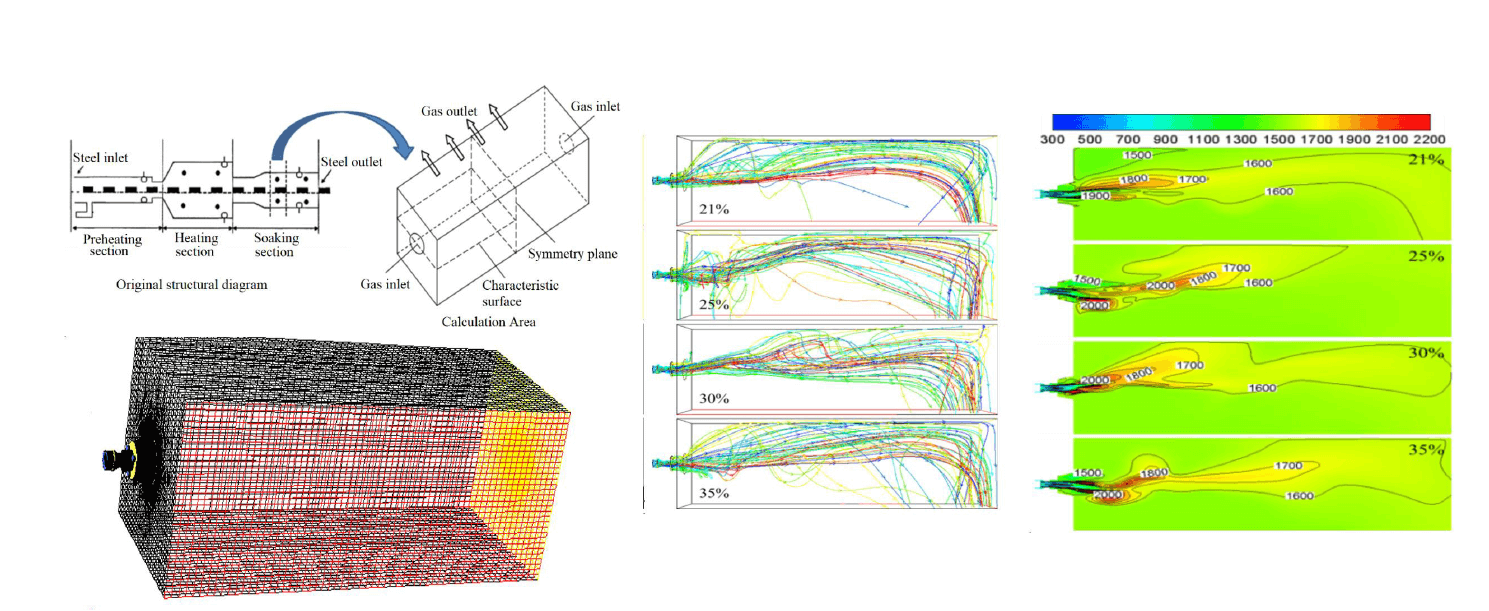
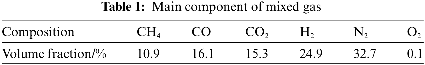
The object of this paper is a pushing steel continuous heating furnace of a company. The heating furnace can be divided into preheating section, heating section, and heat uniform section from the temperature control. The furnace width is 12 m, and the furnace height is between 1.6 and 2.2 m. Along the furnace length, symmetrical burners are arranged on both sides of the furnace for mutual jet combustion heating. The burner adopts a low NOX mixed gas flame-controlling burner, and the distance between the burner and the burner is 2 m. The combustion air of the burner is supplied through central air, primary air, and secondary air. The primary air adopts the way of swirl, and the proportion of primary air and secondary air can be adjusted. The furnace uses mixed gas as fuel, and the composition of mixed gas is shown in Table 1.
This paper selects a set of burners in the soaking zone of the pushing-type continuous heating furnace for simulation calculation. The furnace height is 2 m and the burners are in the center of the furnace wall. Fig. 1 shows the heating furnace and the structural sketch of the calculation area. As can be seen from Fig. 1, the furnace width direction of the soaking zone is symmetrical along the center, so only half of the furnace width direction is taken in the calculation process, and the symmetric surface is set as the symmetric boundary condition in the calculation in FLUENT.
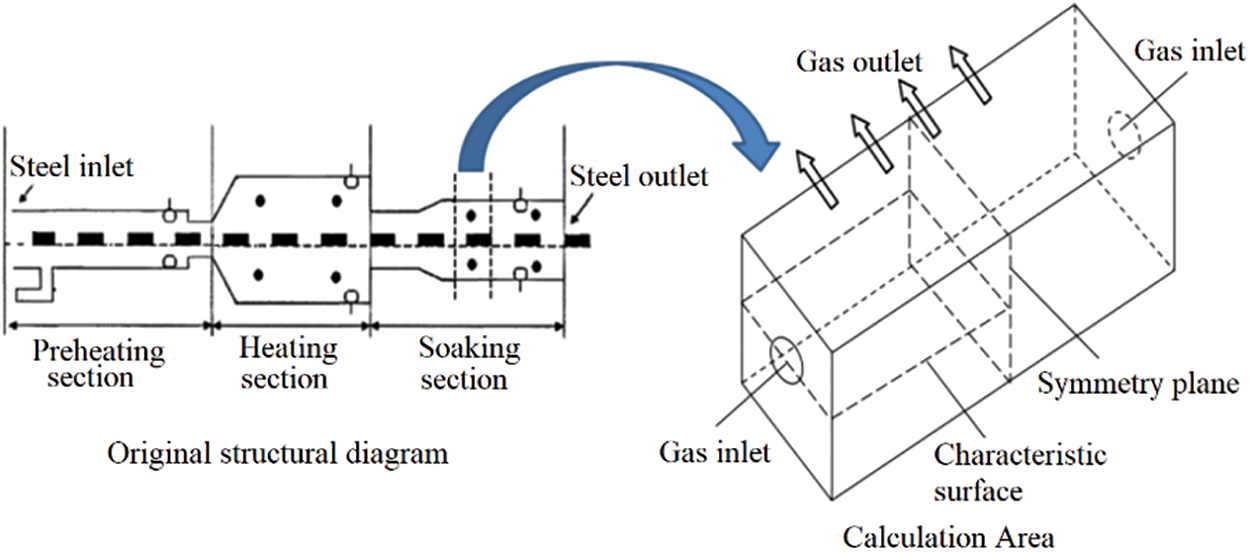
Figure 1: Schematic diagram of geometric model of heating furnace research section
The mathematical models established in this paper are based on the basic conservation equation, combined with experimental techniques and theoretical analysis techniques, with the purpose of application, the basic conservation equation is moderately simplified, and the physical process is more specifically described in mathematics. Based on the continuity equation, momentum conservation equation, and energy equation, the mathematical models used in this paper are mainly the RNG bi-equation model, eddy dissipation (EBU) model, discrete ordinates (DO) model, and NOX generation model. In the combustion process of the burner studied in this paper, gas, and air are mixed and burned after being injected into the furnace, so it belongs to non premixed combustion. The non premixed combustion model is very commonly used in calculating turbulent diffusion flames in rapid chemical reaction systems. Meanwhile, as the combustion model does not require solving the component transport equation, the chemical reaction calculation part is also completed in the pre PDF.
2.3.1 Determination of Inlet Boundary Conditions
In the model studied in this paper, there are three air mass flow inlet boundaries and one gas mass flow inlet boundary. According to the field data, the mass flow of gas inlet is 726 m3/h, and the temperature is 20°C; the central air supply to the burner accounts for 3% of the total air volume, and the proportion of primary air and secondary air can be adjusted. The mass flow of the air inlet is calculated according to the air consumption coefficient (1.06) and the oxygen content in the air, and the temperature is 520°C.
2.3.2 Determination of Export Boundary Conditions
Pressure outlet boundary conditions are adopted, and the pressure value of the outlet is given as one atmosphere. The reflow gas at the outlet is the flue gas after complete combustion, and its temperature is set as the average temperature of the gas in the furnace.
2.3.3 Determination of Boundary Conditions of Furnace Wall
The tangential velocity of the fluid on the solid wall satisfies the condition of no slip velocity,and the normal velocity satisfies the condition of no penetration. The furnace wall is treated according to the thermal conductive solid boundary condition, and the inner lining surface is treated according to the second type of boundary condition, namely the equal heat flow boundary condition. The heat flux density is calculated according to Eq. (1).
Here
After calculation, the approximate heat flux density of the furnace top is −1230 W/m2, and the heat flux density of the side wall is −800 W/m2.
2.3.4 Determination of Billet Boundary Conditions
Assuming that the bottom of the furnace is the upper surface of the billet, as a wall surface, the tangential velocity of the fluid should also meet the no slip velocity condition, and the normal velocity to meet the no penetration condition. In addition, the first type of boundary conditions, namely isothermal boundary conditions, are adopted. According to the field data, the temperature is set at 1200°C, and the surface blackness is set at 0.8.
Fig. 2 shows the grid of the calculation area generated by Gambit software. The burner has a complex and irregular structure, with large variations of cross-sectional dimensions and drastic flow changes. Encrypted structured grids are used for these parts. Structured hexahedral grids are used for the nozzle and combustion area, which gradually become sparse with the development of flow. The grid generation of the entire heating furnace geometry model is completed according to the above method, with a total number of about 700,000 grid nodes.
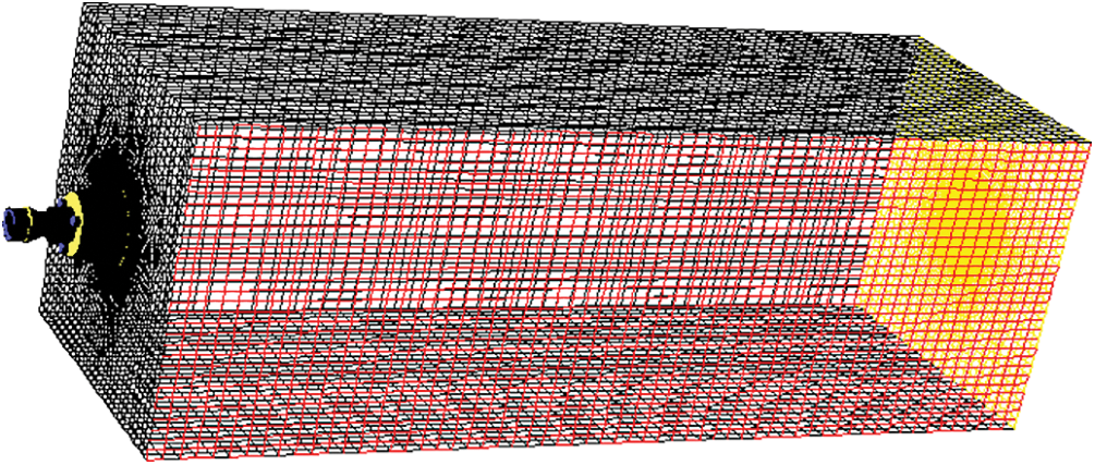
Figure 2: Schematic diagram of calculating grid division of heating furnace
3 Analysis of Simulation Results
Considering only the combustion characteristics with the air oxygen content ranging from 21% to 35%, the simulation conditions used are shown in Table 2, and the air consumption coefficient is taken as 1.06. Primary air refers to the airflow supplied at the center of the burner, mainly used to stabilize the combustion flame. The secondary air is distributed around the periphery of the burner and diffuses with the fuel in the center for combustion. Wind ratio refers to the ratio of primary and secondary air volume.
3.1 Comprehensive Analysis of Combustion Process in Furnace
Fig. 3 shows the flow field trace chart and characteristic surface velocity distribution cloud chart’s change law with the variation of oxygen content in the air under different primary and secondary air ratios. As can be seen from the trace map, the symmetrical arrangement of the burners on both sides of the furnace wall causes the airflow in the furnace to produce the effect of counter-injection at the central symmetrical surface, thus producing a certain reflux effect on the airflow in the furnace. In addition, due to the gas suddenly getting into the large space through the entrance, on the one hand, the flow direction needs to be expanded, and on the other hand, the wall pressure will also form a part of the reflux gas. These reflux gases improve the distribution of airflow and temperature in the furnace and the mixing of gas components to some extent and make a part of high-temperature products reflux to the flame root, which helps stabilize the flame.
Figure 3: Flow field track and characteristic surface velocity profile under different primary and secondary wind ratio conditions
Fig. 4 shows the CO concentration distribution cloud chart on the characteristic surface under the conditions of 1:3 and 1:7 primary and secondary air ratios. As can be seen from the figure, the combustion in the furnace is completely sufficient under different oxygen content in the air and primary and secondary air ratios, which is basically consistent with the actual situation. The mixed airflow of fuel and oxygen-rich air has a fierce combustion reaction just after entering the furnace. As can be seen from the figure, the combustion is basically completed at the half of the furnace, and the fuel entering the furnace is basically completely burned.
Figure 4: CO concentration distribution diagram on characteristic surface
The average volume concentration of CO2 in the heating furnace under different combustion schemes. As can be seen from the figure, the content of CO2 in the heating furnace increases with the increase of oxygen content in the air, and the trend is very obvious. When the oxygen content in the air increases to 35%, the average volume concentration of CO2 in the furnace increases by about 40% compared with that under conventional air combustion, which is very beneficial to the separation and recovery of CO2.
3.2 Comprehensive Analysis of Temperature Field in Furnace
Fig. 5 shows the variation law of characteristic surface temperature distribution with oxygen content in the air under different primary and secondary air ratios. The figure shows that the temperature field distribution of different schemes is similar, and the temperature gradually increases along the airflow direction, and then gradually decreases when it reaches a maximum value. This is because the diffusion combustion process occurs, and the fuel is burned while it is mixed with air. The high-temperature flue gas of combustion transfers heat to the unburned mixture, causing it to combust. The heat released by the combustion reaction of the unburned mixture is much greater than its heat absorption, so the heat released by the combustion reaction gradually increases until the fuel as well as the CO produced by pyrolysis are burned out, and the temperature reaches the highest value. Subsequently, as the high-temperature flue gas lost its heat source, and radiated heat to the surroundings, the temperature of the flue gas decreased gradually.
Figure 5: Temperature distribution diagram of characteristic surface under different primary and secondary air ratios
As can be seen from Fig. 5, with the increase of oxygen content in the air, the furnace temperature gradually rises, and the flame shape remains almost unchanged under different oxygen content in the air. However, the temperature of the flame peak rises with the increase of oxygen content in the air, and the high-temperature area in the flame center becomes more and more obvious, indicating that the application of enriched oxygen improves the combustion rate of fuel and changes the heat dissipation characteristics of the combustion field. However, the emergence of local high-temperature area in the furnace is not favorable for enriched oxygen combustion.
To better compare the furnace combustion conditions under different oxygen content, the highest combustion temperature, highest furnace temperature, average furnace temperature, and uneven coefficient of furnace temperature are used as comparison parameters. The uneven coefficient of furnace temperature is defined as formula (2), which refers to the degree of deviation of gas temperature at each position in the furnace from the average temperature. The greater the uneven coefficient is, the greater the degree of deviation of gas temperature at each position in the furnace from the average temperature is, that is, the worse the unevenness of temperature in the furnace is
Here Ti and Tave respectively represent the temperature of each cell in the furnace calculation area and the average temperature of the furnace calculation area, K, Vi and V respectively represent the volume of each cell in the furnace calculation area and the volume of the furnace calculation area, m3.
Fig. 6 shows the variation law of the above four parameters with the oxygen content in the air under different one or two air ratio conditions. It can be seen from the figure that the maximum temperature of combustion, the maximum temperature in the furnace, and the average temperature in the furnace increase with the increase of the oxygen content in the air. There are two reasons for this: on the one hand, with the increase of oxygen-rich concentration, the probability of collision between gas molecules and oxygen molecules increases when gas and air are at the same mixing level, thus accelerating the combustion reaction speed and shortening the flame. Compared with the long flame, the heat released by the combustion reaction is released in a smaller space in a shorter time, and the combustion temperature rises rapidly; on the other hand, the increase of oxygen-rich concentration will reduce the amount of nitrogen carried in the air, so that the volume of flue gas generated eventually decreases, and the flue gas can be heated to a higher temperature when the same combustion reaction heat is released.
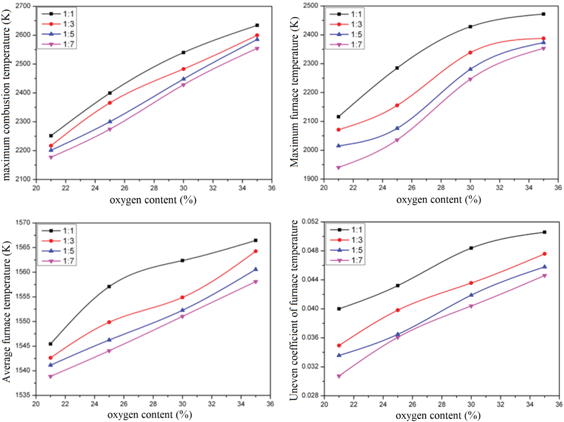
Figure 6: Diagram of combustion temperature under different primary and secondary air ratios
In addition, it can be seen that the maximum combustion temperature and the average furnace temperature show an approximate linear growth law with the oxygen content in the air, but the maximum temperature’s increasing trend with the oxygen content in the air in the furnace gradually slows down.
Furthermore, the difference between the highest temperature of combustion and the highest temperature in the furnace also shows that during the operation of the reheating furnace, the highest temperature of combustion occurs at the burner position, which makes the use of the burner in a harsh environment, which is not conducive to the operation of the burner.
3.3 Comprehensive Analysis of NOX Generation in Furnace
Fig. 7 displays the NOX emission concentration values for different schemes. The concentration mentioned here refers to the NOX emission concentration, which is corrected in dry flue gas with an oxygen content of 11% under standard conditions. The calculation method is presented in formula (3).
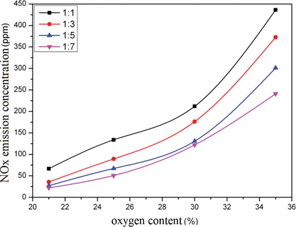
Figure 7: NOX emission concentrations in different scenarios
Here
As can be seen from the figure, when conventional air combustion is adopted, that is, when the oxygen content in the air is 21%, the NOX emission concentration is the minimum. Therefore, with the increase of the oxygen content in the air, the NOX emission concentration gradually increases and rises exponentially. When the oxygen content in the air is 35%, the NOX emission concentration is about 10 times that of conventional air combustion. The reason for this phenomenon is that the NOX produced by gas combustion is mainly thermal type, and the thermal type NOX rises exponentially with the temperature. After the adoption of oxygen-enriched combustion, there is a relatively large increase in the combustion temperature of the heating furnace, and the oxidizing atmosphere in the furnace is strengthened. Therefore, the NOX emission will increase with the increase of the oxygen content in the air.
The adoption of oxygen-enriched combustion technology will lead to an increase in NOX emissions. Analysis shows that, on the one hand, due to the energy-saving effect of oxygen-enriched combustion, under the condition of constant energy demand, NOX emissions can be reduced due to the reduction of fuel consumption and flue gas amount. On the other hand, due to the high flame temperature of oxygen-enriched combustion, the thermal NOX generation in gas flame is greatly increased. Therefore, in general, after the adoption of oxygen-enriched combustion technology, the total amount of NOX emissions is multiplied, at which time the combustion mode must be changed, or other measures must be taken to reduce NOx generation.
In addition, when the ratio of primary air to secondary air is 1:1, the NOX emission concentration is the largest, and then with the increase of secondary air, the NOX emission concentration gradually decreases. This is also due to the increase of secondary air, making the combustion temperature of the heating furnace reduce, resulting in the reduction of thermodynamic NOX generated in the furnace. Generally, the simulation results show that staged combustion can effectively reduce NOX emissions.
(1) With the increase of oxygen content in the air, the velocity of gas in the furnace decreases and the flame length tends to be shorter, but the combustion temperature in the furnace rises, which makes the temperature distribution in the furnace more uneven, which is not conducive to the heating of the billet, but also makes the burner operate in a more harsh environment, which will reduce the service life of the burner.
(2) Oxygen-enriched combustion increases the emission concentration of NOX. When conventional air combustion is changed into oxygen-enriched air combustion with 35% oxygen content, the emission concentration of NOX increases by about 10 times. At this time, the combustion mode must be changed, or other measures must be taken to reduce the generation of NOX.
(3) In staged combustion, the increase of secondary air volume can effectively reduce NOX emissions.
Acknowledgement: The authors acknowledge the National Natural Science Foundation of China.
Funding Statement: Supported by the National Natural Science Foundation of China (52330003).
Author Contributions: The authors confirm their contribution to the paper as follows: study conception and design: Fuyong Su; data collection: Xiaojun Li; analysis and interpretation of results: Fuyong Su, Xiaojun Li; draft manuscript preparation: Fuyong Su, Xiaojun Li. All authors reviewed the results and approved the final version of the manuscript.
Availability of Data and Materials: The authors confirm that the data supporting the findings of this study are available within the article.
Conflicts of Interest: The authors declare that they have no conflicts of interest to report regarding the present study.
References
1. Chan DYL, Yang KH, Lee JD, Hong GB. The case study of furnace use and energy conservation in iron and steel industry. Energy. 2010;35(4):1665–70. doi:10.1016/j.energy.2009.12.014. [Google Scholar] [CrossRef]
2. Zhu T, Hu Y, Tang C, Wang L, Liu X, Deng L, et al. Experimental study on NOx formation and burnout characteristics of pulverized coal in oxygen enriched and deep-staging combustion. Fuel. 2020;272:117639. doi:10.1016/j.fuel.2020.117639. [Google Scholar] [CrossRef]
3. Yihao X, Yaojie T, Hu J, Congcong L, Zean W, Hao L. Numerical study on a novel burner designed to improve MILD combustion behaviors at the oxygen enriched condition. Appl Therm Eng. 2019;152:686–96. doi:10.1016/j.applthermaleng.2019.02.023. [Google Scholar] [CrossRef]
4. Zhou ZF, Xue QG, Li CL, Wang G, She XF, Wang JS. Coal flow and combustion characteristics under oxygen enrichment way of oxygen-coal double lance. Appl Therm Eng. 2017;123:1096–105. doi:10.1016/j.applthermaleng.2017.05.177. [Google Scholar] [CrossRef]
5. Chen M, Bo L, Dongmei C, Terrence W, Wenchao M, Fawei L, et al. An investigation of an oxygen-enriched combustion of municipal solid waste on flue gas emission and combustion performance at a 8 MWth waste-to-energy plant. Waste Manage. 2019;96:47–56. doi:10.1016/j.wasman.2019.07.017. [Google Scholar] [CrossRef]
6. Gong CM, Li JB, Peng LG, Chen YL, Liu ZL, Wei FX. Numerical investigation of intake oxygen enrichment effects on radicals, combustion and unregulated emissions during cold start in a DISI methanol enginet. Fuel. 2019;253:1406–13. doi:10.1016/j.fuel.2019.05.140. [Google Scholar] [CrossRef]
7. Baskar P, Senthilkumar A. Effects of oxygen enriched combustion on pollution and performance characteristics of a diesel engine. Eng Sci Technol. 2016;19(1):438–43. [Google Scholar]
8. Xu SS, Yang YL, Shi ZM, Liu FH, Wu H, Xiao YQ. Research on oxy-fuel combustion of blended coal in precalciner kiln. J Cent South Univ. 2017;48(11):3116–25. [Google Scholar]
9. Engin B, Kayahan U, Atakül H. A comparative study on the air, the oxygen-enriched air and the oxy-fuel combustion of lignites in CFB. Energy. 2020;196:117021. doi:10.1016/j.energy.2020.117021. [Google Scholar] [CrossRef]
10. Zhou AQ, Xu HP, Tu YJ, Zhao FY, Zheng ZM, Yang WM. Numerical investigation of the effect of air supply and oxygen enrichment on the biomass combustion in the grate boiler. Appl Therm Eng. 2019;156:550–61. doi:10.1016/j.applthermaleng.2019.04.053. [Google Scholar] [CrossRef]
11. Schluckner C, Gaber C, Demuth M, Forstinger S, Prieler R, Hochenauer C. CFD-model to predict the local and time-dependent scale formation of steels in air-and oxygen enriched combustion atmospheres. Appl Therm Eng. 2018;143:822–35. doi:10.1016/j.applthermaleng.2018.08.010. [Google Scholar] [CrossRef]
12. Prieler R, Mayr B, Demuth M, Holleis B, Hochenauer C. Numerical analysis of the transient heating of steel billets and the combustion process under air-fired and oxygen enriched conditions. Appl Therm Eng. 2016;103:252–63. doi:10.1016/j.applthermaleng.2016.04.091. [Google Scholar] [CrossRef]
13. Han SH, Lee YS, Cho JR, Lee KH. Efficiency analysis of air-fuel and oxy-fuel combustion in a reheating furnace. Int J Heat Mass Tran. 2018;121:1364–70. doi:10.1016/j.ijheatmasstransfer.2017.12.110. [Google Scholar] [CrossRef]
14. Prieler R, Mayr B, Demuth M, Holleis B, Hochenauer C. Prediction of the heating characteristic of billets in a walking hearth type reheating furnace using CFD. Int J Heat Mass Tran. 2016;92:675–88. doi:10.1016/j.ijheatmasstransfer.2015.08.056. [Google Scholar] [CrossRef]
15. Mayr B, Prieler R, Demuth M, Hochenauer C. Comparison between solid body and gas radiation in high temperature furnaces under different oxygen enrichments. Appl Therm Eng. 2017;127:679–88. doi:10.1016/j.applthermaleng.2017.08.054. [Google Scholar] [CrossRef]
16. Shirneshan A, Amiri M, Zare A. Effects of oxygen addition on thermal and pollutant emission characteristics of a cylindrical furnace fueled with 1-Hexanol-biodiesel–diesel blends. Energy Rep. 2023;10:2080–9. doi:10.1016/j.egyr.2023.09.014. [Google Scholar] [CrossRef]
17. Motamedifar N, Shirneshan A. An experimental study of emission characteristics from cylindrical furnace: effects of using diesel-ethanol-biodiesel blends and air swirl. Fuel. 2018;221:233–9. doi:10.1016/j.fuel.2018.01.018. [Google Scholar] [CrossRef]
18. Emadi A, Saboonchi A, Taheri M, Hassanpour S. Heating characteristics of billet in a walking hearth type reheating furnace. Appl Therm Eng. 2014;63(1):396–405. doi:10.1016/j.applthermaleng.2013.11.003. [Google Scholar] [CrossRef]
19. Zhang C, Ishii T, Hino Y, Sugiyama S. The numerical and experimental study of non-premixed combustion flames in regenerative furnaces. J Heat Transfer. 2000;122(2):287–93. doi:10.1115/1.521466. [Google Scholar] [CrossRef]
20. Huang MJ, Hsieh CT, Lee ST, Wang CH. A coupled numerical study of slab temperature and gas temperature in the walking-beam-type slab reheating furnace. Numer Heat Transf Part A Appl. 2008;54(6):625–46. doi:10.1080/10407780802289475. [Google Scholar] [CrossRef]
21. Jaklic A, Vode F, Kolenko T. Online simulation model of the slab-reheating process in a pusher type furnace. Appl Therm Eng. 2007;27(5–6):1105–14. [Google Scholar]
22. Han SH, Chang D, Kim CY. A numerical analysis of slab heating characteristics in a walking beam type reheating furnace. Int J Heat Mass Transf. 2010;53(19–20):3855–61. [Google Scholar]
23. Han SH, Chang D. Optimum residence time analysis for a walking beam type reheating furnace. Int J Heat Mass Transf. 2012;55(15–16):4079–87. [Google Scholar]
24. Casal JM, Porteiro J, Míguez JL, Vázquez A. New methodology for CFD three dimensional simulation of a walking beam type reheating furnace in steady state. Appl Therm Eng. 2015;86:69–80. doi:10.1016/j.applthermaleng.2015.04.020. [Google Scholar] [CrossRef]
25. Li Z, Barr PV, Brimacombe JK. Computer simulation of the slab reheating furnace. Can Metall. 1988;27(3):187–96. doi:10.1179/cmq.1988.27.3.187. [Google Scholar] [CrossRef]
26. Chen S, Poshard D, Abraham S. Modifification of reheat furnace practices through comprehensive process modeling. Iron Steel Technol. 2008;5(8):66–79. [Google Scholar]
27. Jang J, Kim SW. An estimation of a billet temperature during reheating furnace operation. Int J Control Automation Syst. 2007;5(1):43–50. [Google Scholar]
28. Wang S, Xiao J, Wang J, Jian G, Wen J, Zhang Z. Application of response surface method and multi-objective genetic algorithm to confifiguration optimization of shell-and-tube heat exchanger with fold helical baffs. Appl Therm Eng. 2018;129:512–20. doi:10.1016/j.applthermaleng.2017.10.039. [Google Scholar] [CrossRef]
29. Jang JY, Huang JB. Optimization of a slab heating pattern for minimum energy consumption in a walking beam type reheating furnace. Appl Therm Eng. 2015;85:313–21. doi:10.1016/j.applthermaleng.2015.04.029. [Google Scholar] [CrossRef]
30. Gu MY, Chen G, Liu X, Wu C, Chu H. Numerical simulation of slab heating process in a regenerative walking beam reheating furnace. Int J Heat Mass Transfer. 2014;76:405–10. doi:10.1016/j.ijheatmasstransfer.2014.04.061. [Google Scholar] [CrossRef]
Cite This Article
 Copyright © 2024 The Author(s). Published by Tech Science Press.
This work is licensed under a Creative Commons Attribution 4.0 International License , which permits unrestricted use, distribution, and reproduction in any medium, provided the original work is properly cited.
 Downloads
 Citation Tools