
 Submit a Paper
 Propose a Special lssue
 Open Access
ARTICLE

Performance Study of Dynamic Intake and Exhaust Façades in Hot and Dry Climates: Iraq Case Study
School of Mechanical Engineering, Iran University of Science and Technology, Tehran, Iran
* Corresponding Authors: S. M. Hosseinalipour. Email: ; S. Asiaei. Email:
(This article belongs to the Special Issue: Multiscale Heat and Mass Transfer and Energy Conversion)
Frontiers in Heat and Mass Transfer 2024, 22(3), 747-767. https://doi.org/10.32604/fhmt.2024.051541
Received 03 March 2024; Accepted 07 May 2024; Issue published 11 July 2024
 View Full Text
 Download PDF
Abstract
This paper is part of a series addressing the urgent need for effective technologies to reduce energy demand and mitigate climate impact. This study focused on the implementation and development of dynamic insulation technology for a sustainable and energy-efficient future in the region, especially in Iraq. The study assessed the energy efficiency of dynamic insulation technology by analyzing three wall models (static, dynamic, and modified) during the winter season. This paper expands the analysis to include a hot, dry summer scenario, providing valuable insights into the year-round performance of dynamic walls and enabling sustainable and energy-efficient solutions for Iraq’s climate. The study evaluates the thermal efficiency of the dynamic intake and exhaust facades during the cooling season for the city of Baghdad. The finding indicated that the dynamic intake facade reduces energy consumption by 16.3% for the dynamic wall and 17.2% for the modified dynamic wall. In addition, the dynamic exhaust front reduces energy consumption by 46% during the cooling season, with the maximum permissible exhaust air level. Dynamic insulation is suitable for hot and dry climates, improving energy consumption.Keywords
Indeed, the need to supply indoor spaces with larger quantities of fresh and clean air has become paramount. Adequate ventilation and air exchange play a crucial role in reducing the concentration of airborne pollutants and minimizing the risk of virus transmission in enclosed environments. By increasing the ventilation rates and ensuring a sufficient supply of fresh air, indoor air quality can be improved, creating a healthier and safer environment for occupants. However, this process results in a higher heat load that must be removed from the building, resulting in increased energy consumption [1–5]. Dynamic insulation is a type of insulation that takes advantage of the inherent air permeability in fabric buildings to recover heat loss through the active flow of fluid (usually air) against a thermal gradient. It is an effective method where part or all of the heat loss by conduction is reclaimed. This innovative approach is commonly known as dynamic insulation. The flow of fluid in dynamic insulation can be classified into two modes: counterflow and pro-flow. In the counterflow mode, the fluid moves in the opposite direction to the heat flow, facilitating efficient heat recovery. Dynamic insulation or dynamic facades allow for a significant volume of air to be drawn into the building at low air velocities when there is a pressure difference not exceeding 50 Pa between the outdoor and indoor environments. It is important to note that maintaining the pressure difference within this range is crucial to prevent difficulties in opening windows and doors [6–9].
The energy consumption of a region is greatly influenced by its geographical location and climate conditions. Iraq experiences hot and dry summers, as well as cold and wet winters. Situated between latitudes 30° and 37° North, Iraq is exposed to high solar radiation, leading to outdoor temperatures in the summer that can surpass 45°C [10]. To provide a visual representation of Baghdad’s climate trends from 2001 to 2019, Fig. 1 showcases the data generated by the Climate Consultant software (version 6.0, 2018). Due to Iraq’s hot and dry climate in summer, there is a necessity to condition outdoor air to the desired comfortable humidity and temperature before supplying it to indoor spaces. Iraq is recognized as one of the countries most susceptible to desertification and climate change. These factors underscore the immediate necessity to tackle climate change impacts and adopt effective measures for climate mitigation in Iraq [11–13]. In this regard, the use of dynamic facades (Dynamic Insulation) provides a solution by pre-cooling the air before it enters the building, thus reducing the overall cooling demand and energy consumption. This approach helps achieve a balance between ensuring adequate supplies of clean air and improving energy efficiency in Iraq’s climatic conditions [14,15]. Gan’s study [16] on dynamically insulated rooms using CFD found that hermetically closed rooms with controlled heat inlets can provide thermal comfort and energy savings. However, if the internal surface temperature is significantly lower than the room air temperature, thermal problems may arise. For leaky buildings, dynamic insulation or heat recovery may not be effective. Careful design is necessary to ensure the inner surface temperature of the insulation wall is close to the room temperature for optimal performance. Elsarrag et al. [14] introduced Energyflo™ Cell, a dynamic insulation product, and evaluate its performance in the hot, humid climate of the UAE. The study demonstrates cost reductions, improved ventilation, and the potential for reducing CO2 emissions. Dynamic insulation can enhance the built environment, lower energy demand, increase property values, and make air conditioning sustainable and affordable, benefiting high-rise buildings. The utilization of dynamic insulation (DI) in building facades offers a promising solution for enhancing energy efficiency. By implementing dynamic insulation, the demand for air conditioning energy can be reduced, all while ensuring the maintenance of indoor air quality and comfort. The integration of DI can lower overall energy consumption, enhance built environments, and contribute to a more sustainable and affordable air conditioning option [17,18]. In their study, Elsarrag et al. [19] focused on enhancing the energy efficiency of building fabric in hot and humid climates through the use of dynamic insulation. The study dealt with the establishment and monitoring of the villa’s environmental outcomes. The results showed that dynamic insulation reduced the increase in fabric conductivity by 41%, indicating its effectiveness in improving energy efficiency. The study proves the suitability of dynamic insulation in hot and humid climates, and has contributed to the development of optimal products for the Gulf region. Further trials are necessary to facilitate wider implementation of this technology. Imbabi [20] introduced Void space dynamic insulation (VSDI), a technology that combines conventional insulation materials with efficient ventilation to create thin wall constructions. VSDI eliminates condensation and overheating risks during the summer, offers energy efficiency, and works well in both hot and cold climates. It can be easily implemented in current building practices and used with other energy-saving technologies. The author recommended conducting research and construction experiments to further explore the practical potential of VSDI. Alongia et al. [21] conducted a study on rock wool samples, analyzing their microscopic geometry and using the volume averaging technique to study fibrous materials. Through numerical simulations, they evaluated thermal dispersion and thermal tortuosity. The results emphasized the significance of porosity in thermal tortuosity and its influence on effective thermal conductivity, providing valuable insights into the thermal behavior of dynamic insulation in building envelopes. Additionally, the study found that thermal dispersion was negligible compared to volume average thermal conductivity. Fantucci et al. [22] presented the results of an experimental campaign on a ventilated double-skin façade (supply air façade and exhaust air façade configuration) using hollow clay bricks. The dynamic insulated systems showed reduced heat losses and the ability to pre-heat supply air. The study highlights the potential of this technology, although further research and integration with HVAC systems are needed.
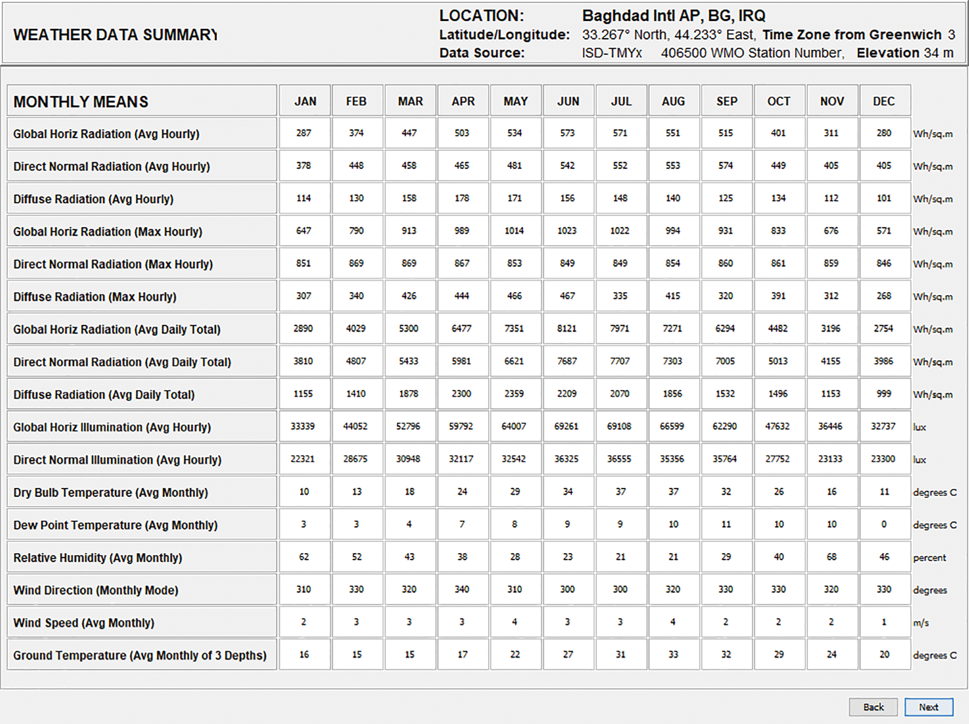
Figure 1: Weather data summary for Baghdad’s climate for the past twenty years from 2001 to 2019 [23]
With increasing awareness of the environmental and economic benefits of dynamic insulation. There is importance in studying the effectiveness of dynamic insulation technology in diverse climatic conditions. Studies on dynamic insulation in hot climates are limited, and there is a lack of studies on its application in hot and dry climates. Iraq’s diverse climate offers a conducive environment for conducting tests and evaluating dynamic insulation performance. This research evaluates the energy efficiency achieved by implementing dynamic insulation at dynamic intake and exhaust facades, specifically during the cooling season. When performing dynamic insulation, it is necessary to ensure that the air drawn into the building does not have a high velocity. By carefully managing air velocity, dynamic insulation can effectively contribute to energy savings and thermal comfort in buildings.
The study focuses on evaluating three typical facades and understanding the physical phenomena associated with the flow of fresh air or exhaust air through these facades. The analysis specifically examines thermal insulation, air movement, and energy efficiency to determine the effectiveness of dynamic insulation facades in the Iraqi climate. To predict the behavior and performance of these facades, numerical simulation using Solidworks Flow Simulation Software (2022) was conducted under specified conditions. The study includes an evaluation of the thermal performance of three models. The first model serves as a reference for comparison, representing a static insulation facade. The second model represents a dynamic insulation facade, while the third model proposes a design aimed at enhancing dynamic insulation performance. The impact of air flow rate on performance is examined through the use of mechanical ventilation. By employing these comprehensive methods, the study aims to provide guidance on construction and design considerations for dynamic insulating facades in the Iraq environment.
Ensuring high indoor air quality (IAQ) is a significant concern with social and economic implications. Various architectural approaches can contribute to achieving successful IAQ, especially in crowded spaces [24,25]. By integrating regulated ventilation, and careful planning for the use of suitable and safe building materials within a comprehensive design strategy, good indoor air quality can be achieved. An approach to consider is the implementation of porous walls or dynamic walls, which function to reduce interior humidity as part of an overall IAQ design strategy. These walls effectively prevent fungal growth on wall surfaces [3,26,27]. In addition to promoting excellent indoor air quality, especially in densely populated urban areas that suffer from air pollution. It serves as both an effective insulator and an exceptional air filter, meeting ventilation requirements outlined by the ASHRAE standard [27,28]. According to the ASHRAE standard, various studies have demonstrated that it is necessary to replace more than half of a home’s volume per hour with fresh air to maintain healthy indoor air quality. This percentage represents the minimum ventilation rates recommended for non-residential buildings [29,30]. Careful selection of porous insulating materials is necessary when using dynamic insulation facades to meet air quality and thermal performance requirements, ensuring optimal results.
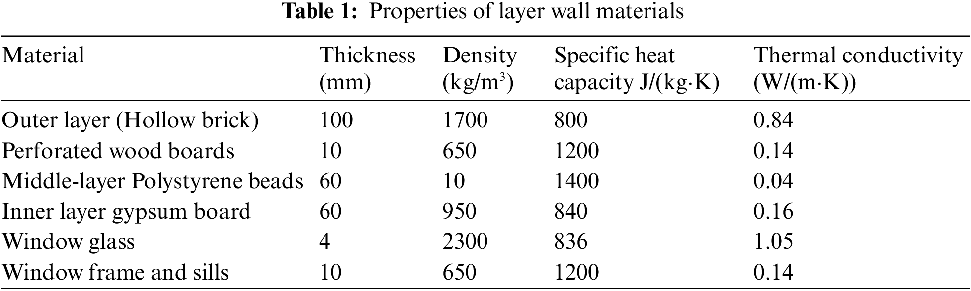
Dynamic insulation facades typically adhere to a consistent design approach to ensure effective implementation of dynamic insulation technology. Dynamic wall design typically includes three distinct layers, separated by air cavities. The outer layer acts as insulation to protect against external environmental conditions. The middle layer acts as an insulating layer, often using a porous, air-permeable material. Finally, the inner layer acts as a heat storage layer, contributing to the overall thermal performance of the facade. On this basis, compatible wall materials and designs were carefully selected. The design proposed for this study incorporates an outer layer composed of hollow clay bricks, with a specific thickness of 100 mm. This choice was made to align with the urban character of the city of Baghdad and ensure compatibility with the local architectural context. The middle layer of the proposed insulating layer comprises polystyrene beads that are packed between two perforated wood panels. These perforated wood panels are specifically designed with a H/L ratio of less than 2, (More details in Appendix A) to ensure optimal performance at the panels [31]. The decision to employ polystyrene beads for dynamic insulation is based on the material’s permeability, ensuring it meets the necessary ventilation requirements. In hot climates like Iraq, the selection of insulating materials for dynamically insulated walls must consider permeability as a crucial factor. To prevent excessive heat accumulation and mitigate the impact of global warming during summer, it is preferable to opt for materials with high permeability [32]. Accordingly, this study proposes the use of polystyrene beads as insulating materials due to their wide availability in the Iraqi market. Moreover, polystyrene exhibits excellent insulation properties, effectively reducing heat transfer through the building envelope. The inner layer of the design comprises a gypsum board with a thickness of 80 mm, in compliance with the local building regulations in the city of Baghdad. Three models were proposed for the study: Model A (static wall), Model B (dynamic wall), and Model C (modified dynamic wall). Model A represents an airtight wall with constant thermal resistance. It serves as a reference point for evaluating the performance of other wall designs. The term “static wall” refers to a model where the thermal resistance remains constant, and the air inside remains at rest. Analyzing the performance of a fixed wall, particularly in terms of thermal resistance and heat transfer, allows for the evaluation of the effectiveness of alternative wall designs. The dynamic wall (Model B) in this study was designed based on insights from previous literature to evaluate the performance of dynamic insulation technology in the specific climate context. Model B includes a ventilation hole at the bottom of the outer layer, allowing fresh air to enter through the porous insulating layer and direct it toward the internal intake fan. The ventilation hole in the outer layer of this wall occupies approximately 0.088% of the total wall area [33]. The modisssfied dynamic wall (Model C), on the other hand, differs from the dynamic wall (Model B) solely in terms of the path through which fresh air enters the wall. Model C draws air directly through an opening in the window sill into the outer wall cavity, eliminating vents in the outer layer. In this modification, the outer layer of the wall does not contain an opening for air entry. This alteration allows for a comparative analysis to determine the impact of the air entry point on the overall performance of the dynamic insulation system. By employing these three distinct models, the study aims to provide comprehensive insights into the performance and effectiveness of static, dynamic, and modified dynamic wall designs in the context of thermal resistance, heat transfer, and energy efficiency. These design differences are represented visually in Figs. 2–4, which display the airflow paths and features of each model.
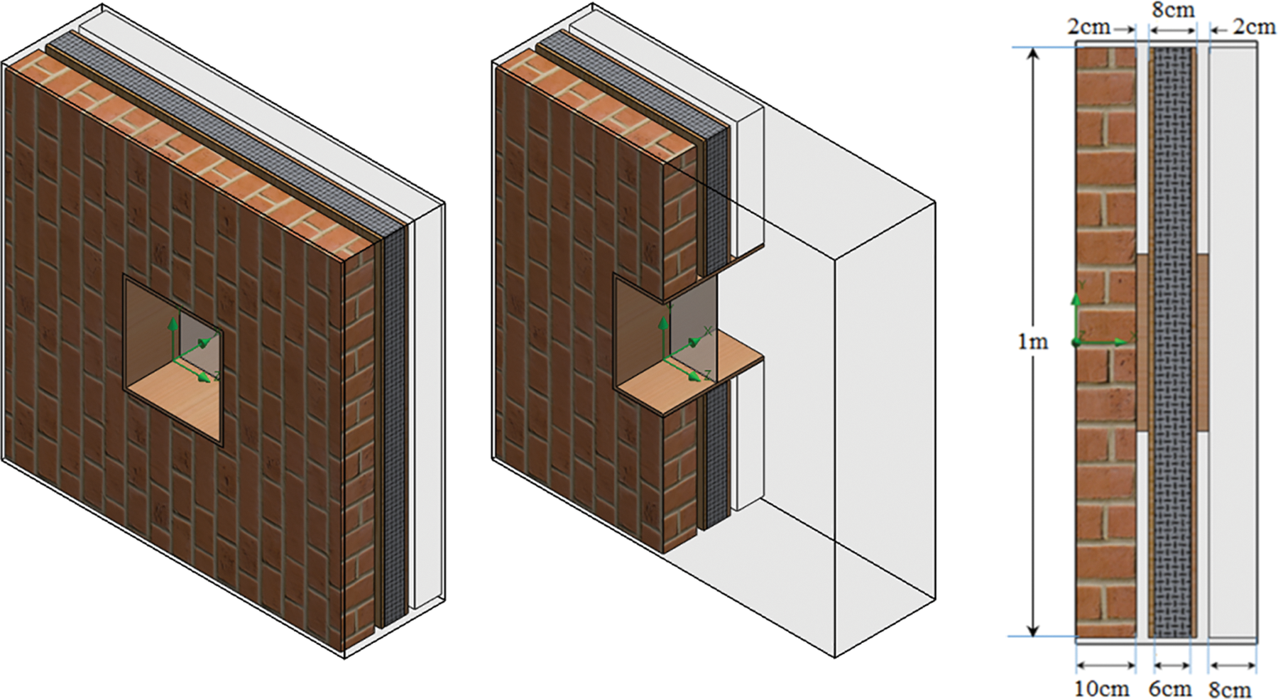
Figure 2: Configuration of the static wall (Model A)
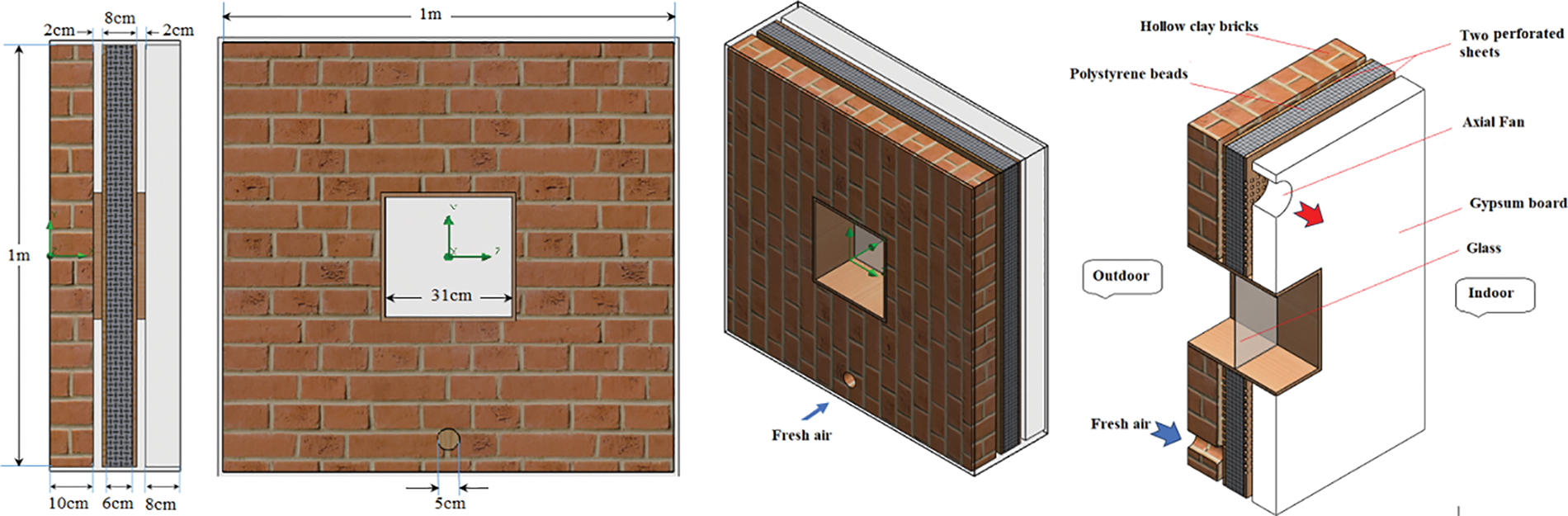
Figure 3: Configuration of the dynamic wall (Model B) with dimensions
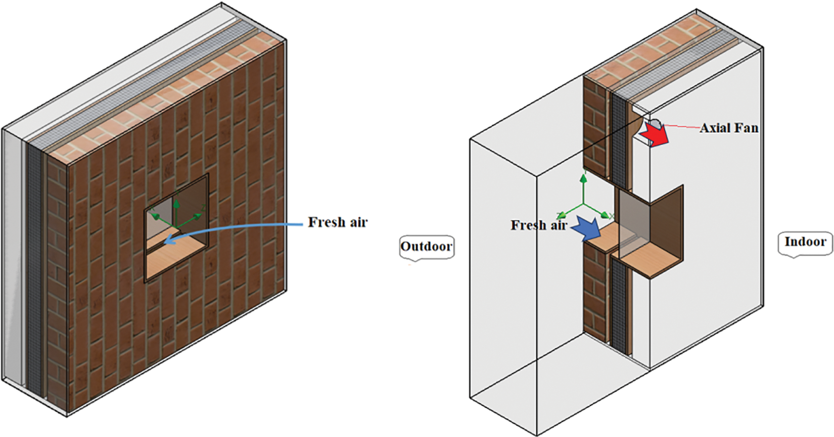
Figure 4: Configuration of the modified dynamic wall (Model C)
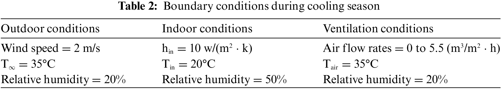
The study simulated three walls under specific conditions and operating modes. It aims to enhance the design and efficiency of dynamic facades through steady-state simulations. This allows for a detailed analysis of their behavior and performance, evaluating different design factors to improve efficiency and overall performance. Solidworks Flow Simulation Software (2022) was used for the simulations and supports dynamic turbulence modeling, heat transfer analysis, and coupled computational calibration of fluid dynamics, heat transfer, and moisture transfer. The average climatic conditions of Baghdad city, specifically the hot dry summer scenario, were considered. The indoor temperature was set to 20°C with 50% relative humidity, while the outdoor temperature was 35°C with 20% relative humidity. An adjustable airflow rate ranging from 0 to 5.5 cubic meters per square meter of wall per hour was achieved using an axial fan. To ensure the effective performance of dynamic walls, preventing excess air leakage is crucial. The building air leakage rate should be kept below 0.6 times the house volume per hour at 50 Pa to avoid impacting the dynamic functionality of the walls [34]. In this study, flow rates for the dynamic wall system were selected based on two conditions: maintaining healthy indoor air quality through required ventilation rates and limiting air velocity to prevent air leakage at a pressure difference not exceeding 20 Pa. This allowed for investigating the impact of different airflow rates on the thermal performance of the walls within the dynamic insulation system. Material properties, thermal boundary conditions, and climatic data were all integrated into the simulation model.
The study involved developing three models (labeled A, B, and C) using Solidworks Flow Simulation Software (2022). Fig. 3 illustrates the airflow path for Model B, while Fig. 4 depicts the airflow path for Model C, specifically focusing on the intake façade configuration. Table 1 provides an overview of the thermal properties of the layers in the walls. These properties are essential in determining the overall thermal performance of the walls and their effectiveness in resisting heat transfer.
To ensure accuracy while minimizing calculation time, tetrahedral meshes were employed for all three models using Solidworks Flow Simulation Software (2022). The quality of the mesh is crucial in obtaining precise numerical solutions in the simulation study. Various mesh sizes were tested based on the U-value, evaluating their sensitivity at an airflow rate of 0.55 m3/(m2
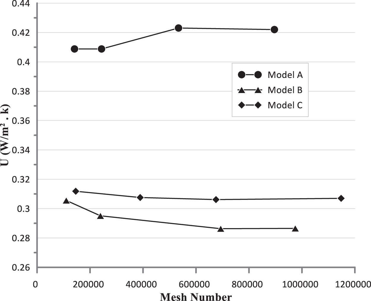
Figure 5: The U-value vs. the number of elements
To accurately simulate convective airflow and conductive heat transfer, it is essential to have a comprehensive understanding of dynamic insulation technology, which involves studying the simultaneous phenomena of fluid flow and heat transfer within porous media. This requires solving a system of simultaneous equations. The system comprises the continuity equation, momentum equation, and energy equation. The general forms of these equations are as follows:
Taking into account the continuity equation of the insulating layer (the porous material), it remains unchanged, except that it is formulated on the basis of its physical velocity.
where:
where:
In its general form, the energy equation can be written as:
where:
Based on the modified energy equation, the transport of energy through the pore layer for fluid and solid can be described as follows:
To establish the boundary conditions for the wall, several factors need to be considered, including wind speed, outdoor temperature, and relative humidity. Collecting climate data in advance is necessary to determine these boundary conditions. Fig. 1 illustrates the determined scenarios for average temperatures, relative humidity, and wind speeds for Baghdad’s climate. Mean climatic conditions are selected for the summer season (June, July, and August). The convection coefficient depends on various factors, including air properties, flow conditions, and surface properties. To calculate the heat transfer coefficient of the surrounding air, the following equation can be used [35]:
where:
The indoor conditions were set to standard recommendations for the cooling season. These conditions include a temperature range of 20°C, relative humidity of 50%, and an air velocity not exceeding 1 m/s. These conditions align with a heat transfer coefficient for the walls that do not exceed 10 W/(m2 · k) [35]. The study did not include radiation in the simulation, which aims to enhance the efficiency of dynamic opaque facades under stationary conditions. Elsarrag et al. [19] focused on air conservation and recycling in a dynamically insulated building in the United Arab Emirates but did not address the specific impact of solar gain in hot and humid climates. Future studies could include radiation to comprehensively understand heat transfer phenomena and inform design decisions. The details of these scenarios are provided in Table 2. By incorporating these scenarios and examining different airflow rates, the study aimed to assess the performance and response of the models under the hot and dry climatic.
Validating digital accounts is crucial to ensuring accuracy and reliability. The code has been calibrated with the study in reference [20]. The boundary conditions and wall geometry were aligned with the description given in the cited reference, also taking into account the values and direction of the airflow. Fig. 6 shows a remarkable agreement between the results of the numerical solution (CFD) and the numerical work of Imbabi as seen in the comparison of U-values for different flow rates. The maximum observed discrepancy in U values is 4.9%. It is plausible that this difference can be attributed to differences in network quality. Based on these results, it can be concluded that the developed numerical approach shows sufficient accuracy.
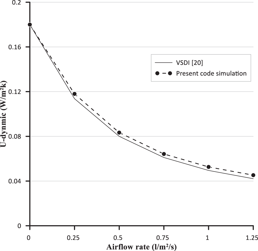
Figure 6: Validation of CFD results for U-dynamic at different air flow rates
In dynamic insulation, an “intake facade” refers to a ventilated facade that provides fresh air. During the cooling season, the system utilizes parallel flow, where the incoming air moves in parallel with the heat transfer. Figs. 7 and 8 illustrated the temperature distribution profiles across the wall layers for models B and C at different airflow rates during the cooling season. When the airflow rate increases in the direction parallel to the heat flow, it gradually reduces the temperature gradient near the hot side of the wall (x/L = 0). On the other hand, at the cool side of the wall, higher airflow rates result in steeper temperature gradients. As the airflow rate increases, the temperature of the inner surface of the wall, specifically the gypsum board layer, also increases. This occurs because as the airflow accelerates, there is insufficient time for the air temperature to decrease to a level closer to the indoor temperature.
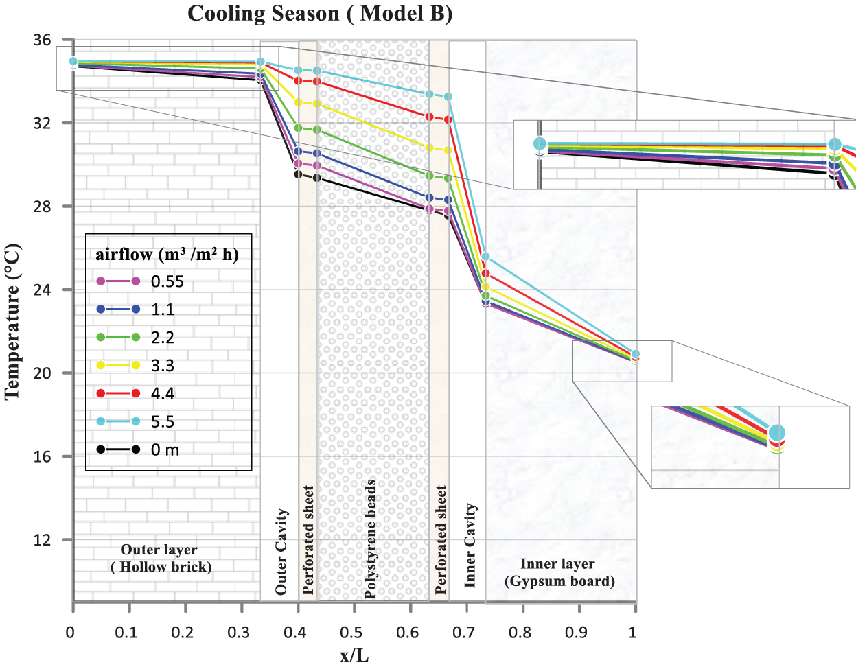
Figure 7: The temperature distribution within the model B with different airflow rate
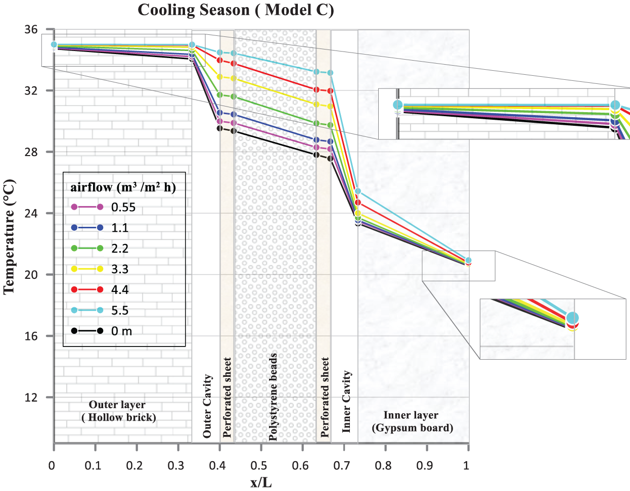
Figure 8: The temperature distribution within the model C with different airflow rate
Eq. (8) allows for the determination of the pre-cooling efficiency of the dynamic wall [22].
where:
Cooling requirements for each of the static and dynamic ventilation include lowering the fresh air temperature to match the indoor air temperature. Both static and dynamic walls necessitate the same ventilation heat to lower the incoming air temperature. This heat is represented by ρa u ca (T∞ − Ti), where ρa denotes air density, u represents air velocity, ca is the specific heat capacity of air, Ti represents the indoor air temperature, and T∞ represents the incoming air temperature. The total heat gain, taking into account both conduction and ventilation, can be calculated using the following equations:
where:
The reduction in cooling requirement of the intake facade can be expressed using the following equation or relationship:
Fig. 9 presents data regarding the percentage decrease in cooling requirements and precooling efficiency for Models B and C during the cooling season. An airflow rate of 1.1 m3/m2 per hour represents the maximum allowable value for both models, as indicated in the figure. Balance is crucial to maintain the benefits of dynamic insulation. It requires achieving an equilibrium between the required fresh air rates and system efficiency. During the cooling season, the precooling efficiency of Models B and C starts at their maximum values of 56% and 52%, respectively, which is achieved at an airflow rate of 0.55 m3/m2 per hour. However, as the airflow rate continues to increase beyond these values, there is insufficient conductive energy to lower the air temperature and match it with the indoor air temperature. Consequently, this situation places a burden on the internal environment, as the internal surface temperature exceeds the desired indoor temperature. Furthermore, for both Models B and C, the percentage reduction in cooling requirements reaches its peak value, equivalent to the heat lost due to conduction. At an airflow rate of 2.2 m3/m2 per hour, the maximum reduction rate in heat requirements was 16.3% for Model B and 17.2% for Model C. It is worth noting that the percentage decrease in cooling requirements and precooling efficiency is significantly lower during the cooling season compared to the heating season (as mentioned in the results of Part B). Dynamic insulation demonstrates greater effectiveness during the heating season due to the counter flow relationship between the heat flow direction and the airflow. Fig. 10 displays the values of
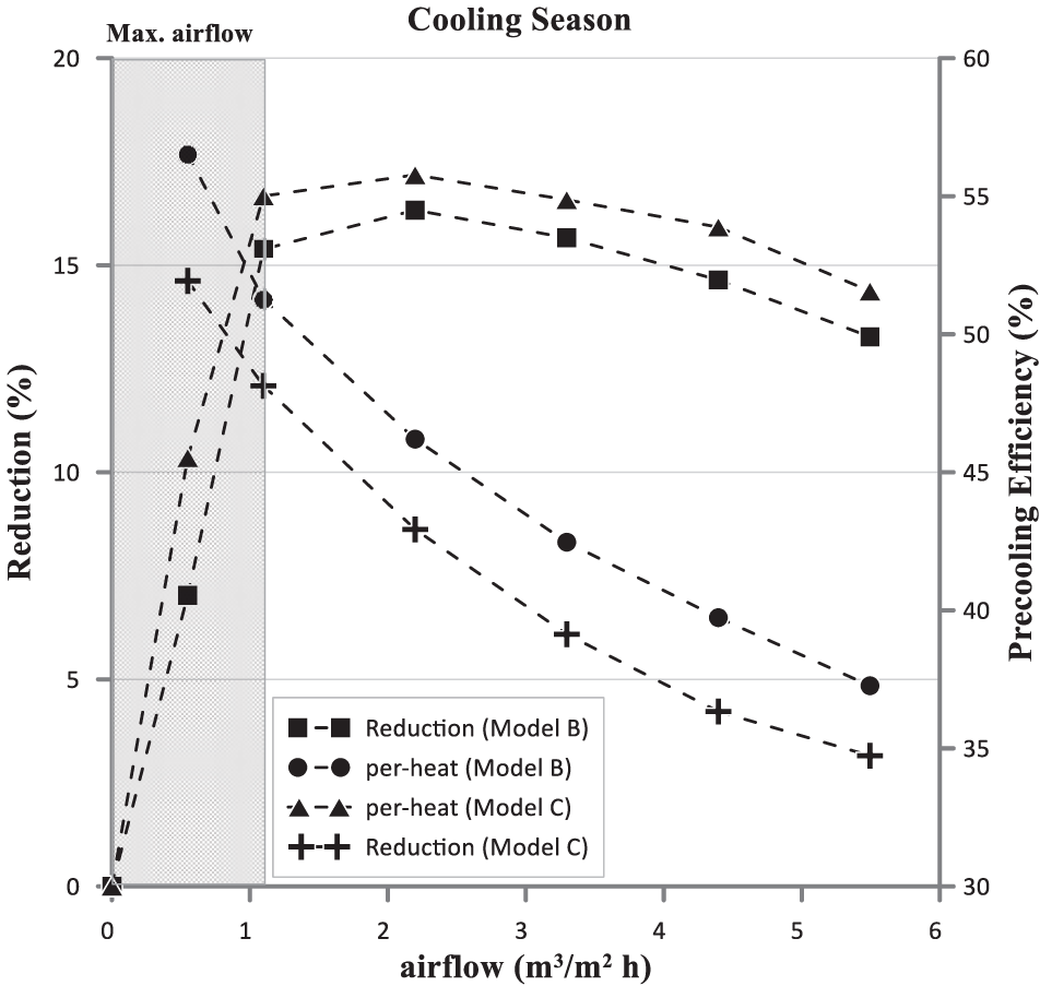
Figure 9: Reduction in cooling requirement and the pre-cooling efficiency vs. air flow rates
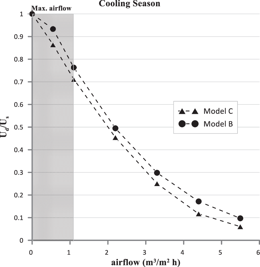
Figure 10: Ud(o)/Us vs. different air flow rates
Fig. 11 illustrates temperature contours for a side view of the wall in three models (A, B, C) during the cooling season. These curves represent the temperature gradient across the wall thickness at an air flow rate of 1.1 m3/m2
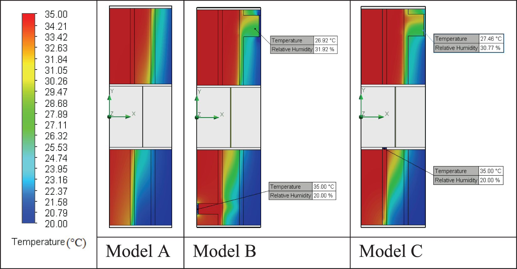
Figure 11: Temperature contours of a side view of the wall for the three models A, B, and C
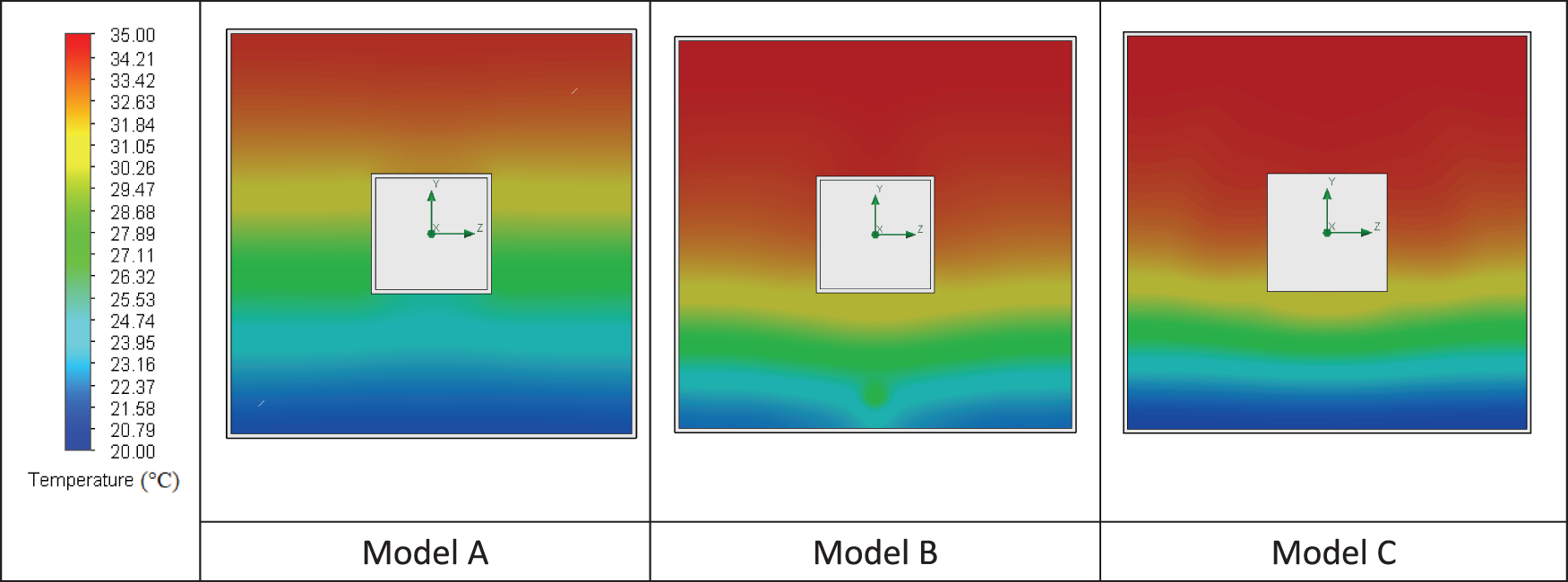
Figure 12: Temperature contours of the insulation layer of three models A, B and C
Fig. 13 illustrates the air flow velocity curves for the intake facade in Models B and C, considering an air flow rate of 1.1 m3/m2
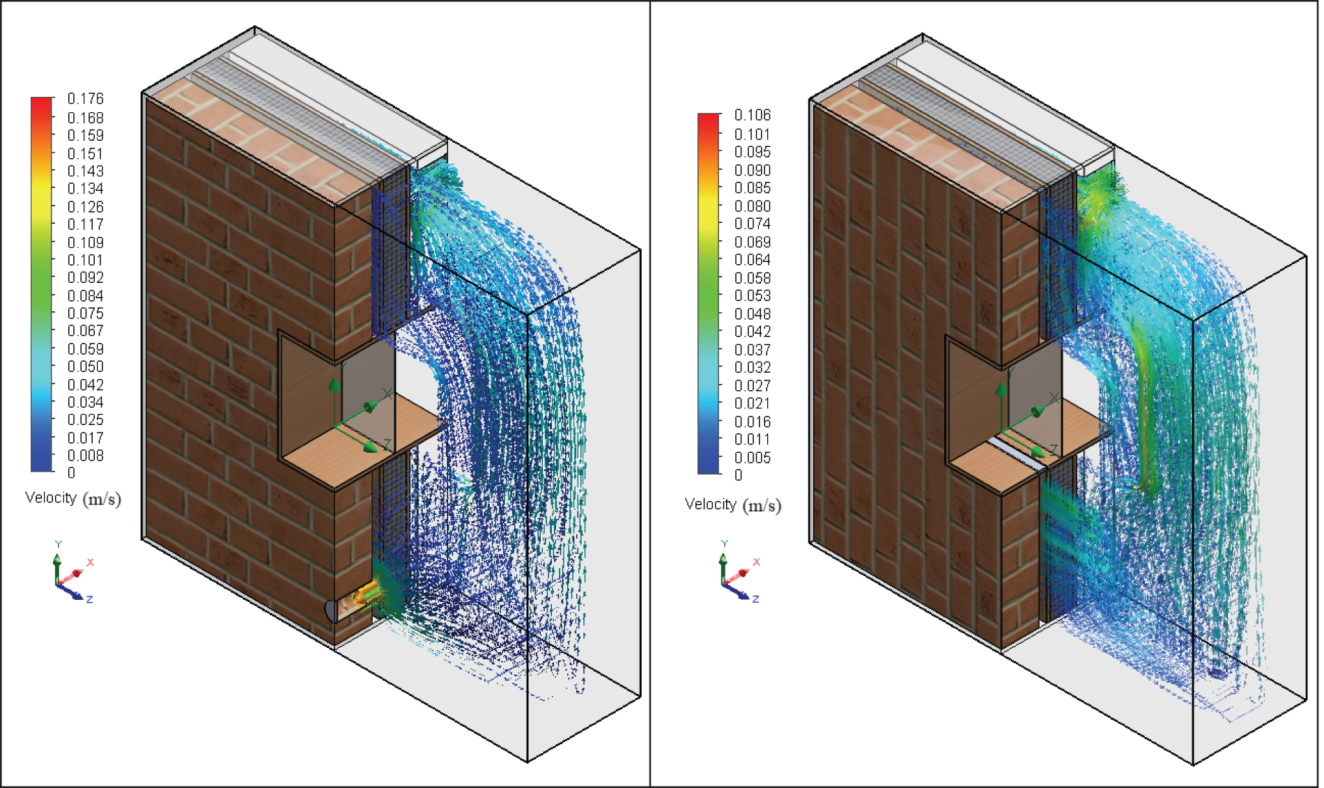
Figure 13: Airflow velocity contours of the intake facades of the two models B and C
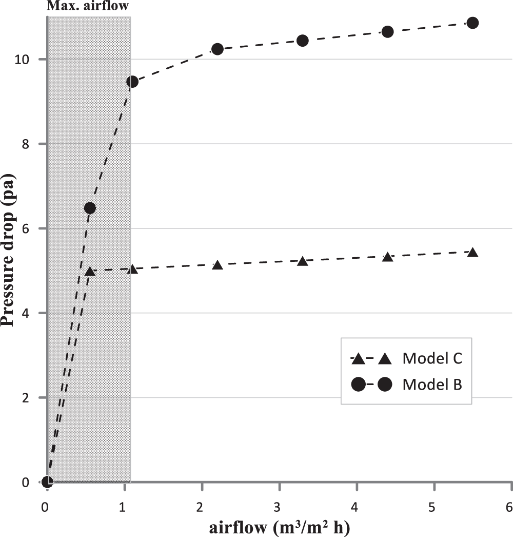
Figure 14: Pressure drop vs. different air flow rates
In dynamic insulation systems, the exhaust facade plays a vital role in recovering cooling or heating energy from the exhaust air. By extracting thermal energy from the exhaust air, which in turn affects the temperature conditions inside the wall or adjacent spaces. Incorporating an exhaust facade is beneficial in enhancing the overall energy efficiency and thermal performance of the building. Fig. 15 depicts the temperature distribution within the layers of the exhaust facade walls during the cooling season, considering different air flow rates. The figure illustrates the impact of varying the exhaust air flow rate on the temperature gradient inside the wall. Increasing the exhaust air flow rate counter to the heat flow gradually flattens the temperature gradient near the cold side of the wall (x/L = 1). On the other hand, higher air flow rates result in steeper temperature gradients observed on the hot side of the wall (x/L = 0). Additionally, raising the air flow rate causes a decrease in the temperature of the inner surface of the wall (gypsum board layer), bringing it closer to or equivalent to the indoor temperature. Fig. 16 displays the
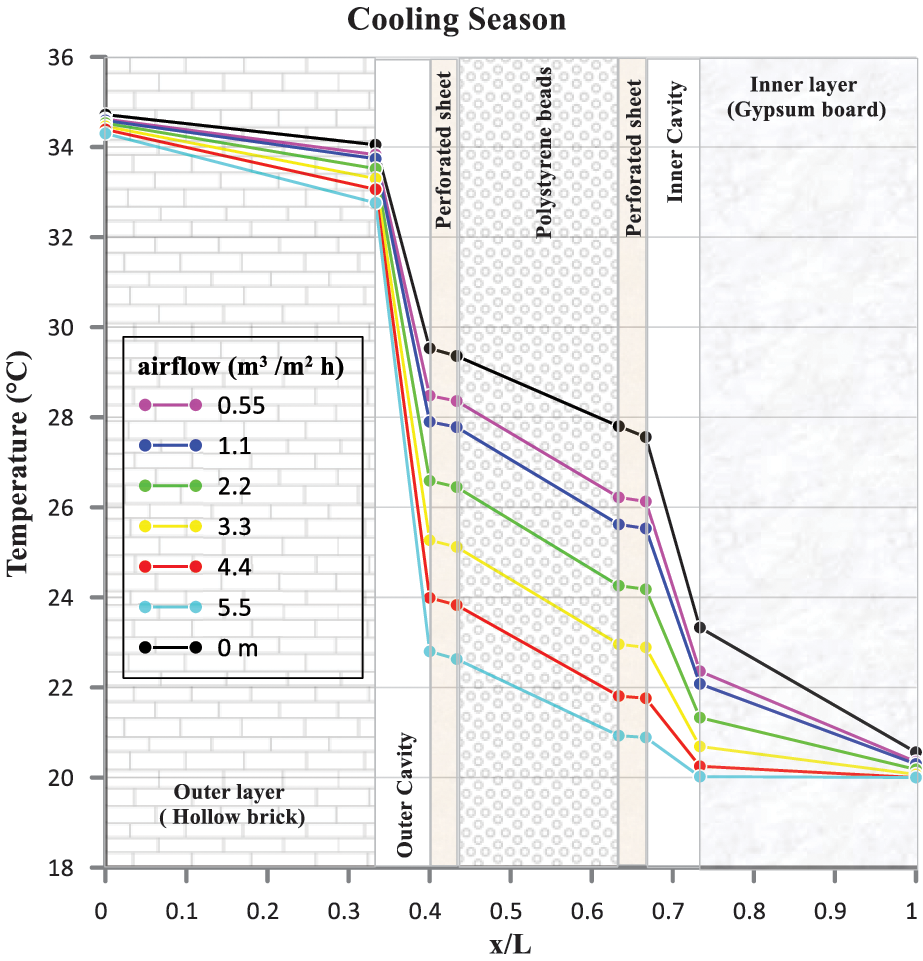
Figure 15: The temperature distribution within the exhaust façade with different airflow rate
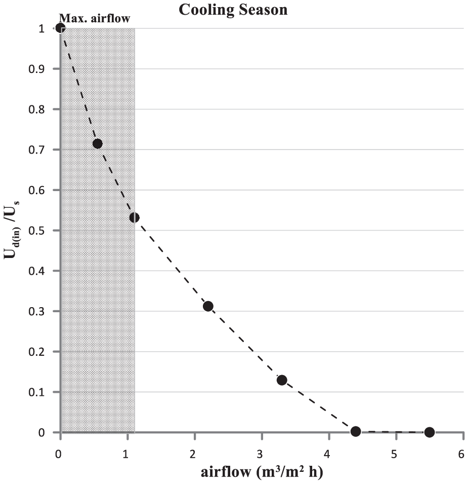
Figure 16: Ud(in)/Us vs. different air flow rates
The mathematical expression or equation that represents the reduction in cooling requirement of the exhaust facade can be expressed as follows:
where:
Fig. 17 presents data on the percentage reduction in cooling requirements and recovery efficiency during the cooling season for the exhaust facade. At the maximum permissible exhaust air flow rate of 1.1 m3/m2 per hour, the recovery efficiency at this air flow rate was found to be 64%. Furthermore, the reduction in heat requirements reached 46% at the maximum permissible exhaust air flow rate. This signifies a significant decrease in the amount of additional cooling needed, resulting in energy savings and improved cooling performance. This could be attributed to the counter flow of airflow and heat, which allows for efficient heat removal from the wall system.
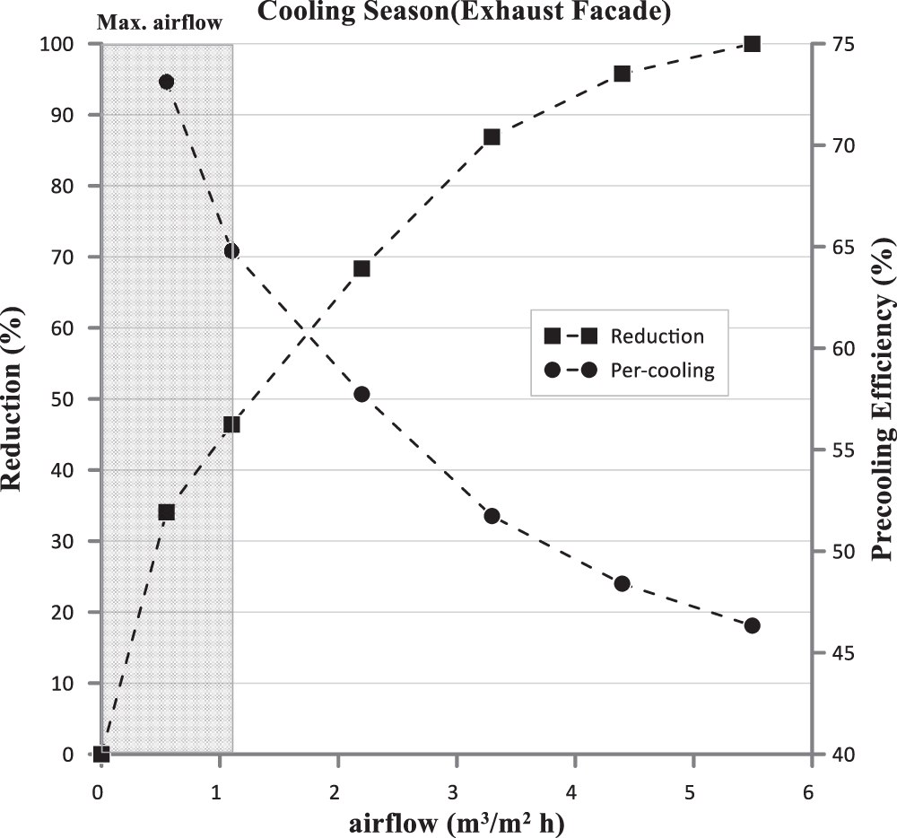
Figure 17: Reduction in cooling and the pre-cooling efficiency vs. air flow rates for exhaust façade
Based on the analyses conducted on three different wall models (Static wall (Model A), dynamic wall (Model B), and modified dynamic wall (Model C)) under the specific hot and dry climatic conditions of Baghdad city, several conclusions were drawn:
• The modified design and use of polystyrene bead insulation have proven effective in Iraq’s hot and dry environment, enhancing performance and providing efficient thermal insulation.
• Dynamic insulation significantly improves the dynamic U-value of the Intake facade. During the cooling seasons, the percentage reduction in its value, compared to the U-value of the static facade, reaches 24% for the dynamic wall, and 29% for the modified dynamic wall, at the maximum permissible level of fresh air.
• The dynamic intake facade reduces energy consumption during the cooling season by up to 16.3% for the dynamic wall, and 17.2% for the modified dynamic wall.
• The intake facade achieves a precooling efficiency of 56% for the dynamic wall, and 52% for the modified dynamic wall, at a flow rate of 0.55 m3/m2
• The dynamic U-value of the exhaust facade achieves a reduction of 48% during the cooling season compared to the static facade, at the maximum permissible exhaust air level.
• The dynamic exhaust facade reduces energy consumption by 46% during the cooling season, at the maximum permissible exhaust air level.
• The exhaust front achieves a maximum recovery efficiency of 73% for the cooling season at a flow rate of 0.55 m3/m2
• Contrary to intake facades, the findings indicate that exhaust facades are particularly effective in the cooling season.
• Dynamic insulation is suitable for hot and dry climates, offering significant energy efficiency benefits.
Finally, future developments for the use of dynamic intake and exhaust facades in Iraq could include integrating smart sensors and automation, exploring integration with renewable energy sources, and adapting the system to specific climatic conditions. Limitations include maintenance and durability, cost considerations, design and integration challenges, and occupant behavior and acceptance. To gain a comprehensive understanding of heat transfer phenomena and inform design decisions, future studies may consider including radiation. Addressing these aspects will contribute to the efficient and sustainable use of this technology in Iraq.
Acknowledgement: The authors express their gratitude to Mustansiriyah University (www.uomustansiriyah.edu.iq) in Baghdad, Iraq, for their support in conducting the present study.
Funding Statement: The authors received no specific funding for this study.
Author Contributions: The authors confirm their contribution to the paper as follows: study conception and design: Hosseinalipour, Asiaei, and Al-Taee; data collection: Al-Taee; analysis and interpretation of results: Al-Taee; draft manuscript preparation: Al-Taee. All authors reviewed the results and approved the final version of the manuscript.
Availability of Data and Materials: The data are available when requested.
Conflicts of Interest: The authors declare that they have no conflicts of interest to report regarding the present study.
References
1. Wang, H., Wang, J., Feng, Z., Yu, C. W., Cao, S. J. (2023). Optimization of ventilation performance of side air supply for large indoor spaces using deflectors and slot air outlets. Indoor Built Environment, 32(2), 323–342. https://doi.org/10.1177/1420326X221108587 [Google Scholar] [CrossRef]
2. Dimitroulopoulou, S., Dudzińska, M. R., Gunnarsen, L., Hägerhed, L., Maula, H. et al. (2023). Indoor air quality guidelines from across the world: An appraisal considering energy saving, health, productivity, and comfort. Environment International, 178, 108127. https://doi.org/10.1016/j.envint.2023.108127. [Google Scholar] [PubMed] [CrossRef]
3. Megahed, N. A., Ghoneim, E. M. (2021). Indoor air quality: Rethinking rules of building design strategies in post-pandemic architecture. Environmental Research, 193, 110471. https://doi.org/10.1016/j.envres.2020.110471. [Google Scholar] [PubMed] [CrossRef]
4. Saheb, H., Mahdi, A., Al-Amir, Q. (2021). A numerical and experimental study of the effect of using personal ventilation systems on indoor air quality in office rooms. Frontiers in Heat Mass Transfer, 16(2151–8629), 1–15. [Google Scholar]
5. Abidi-Saad, A., Bouraoui, M., Popa, C., Polidori, G., Rouabah, M. et al. (2017). Numerical simulation of a double skin with secondary ventilation flow on adiabatic wall. Frontiers in Heat Mass Transfer, 8(2151–8629), 1–6. [Google Scholar]
6. Taylor Bruce, J., Cawthorne, D. A., Imbabi, M. S. (1996). Analytical investigation of the steady-state behaviour of dynamic and diffusive building envelopes. Building and Environment, 31(6), 519–525. https://doi.org/10.1016/0360-1323(96)00022-4 [Google Scholar] [CrossRef]
7. Taylor, B., Imbabi, M. (1998). The application of dynamic insulation in buildings. Renewable Energy, 15(1–4), 377–382. [Google Scholar]
8. Taylor, B. J., Imbabi, M. S. (1997). The effect of air film thermal resistance on the behaviour of dynamic insulation. Building and Environment, 32(5), 397–404. https://doi.org/10.1016/S0360-1323(97)00012-7 [Google Scholar] [CrossRef]
9. Taylor, B. J., Imbabi, M. S. (2000). Environmental design using dynamic insulation. Transactions-American Society of Heating Refrigerating Air Conditioning Engineers, 106(1), 15–28. [Google Scholar]
10. Najim, K. B. (2014). External load-bearing walls configuration of residential buildings in Iraq and their thermal performance and dynamic thermal behaviour. Energy and Buildings, 84, 169–181. https://doi.org/10.1016/j.enbuild.2014.07.064 [Google Scholar] [CrossRef]
11. Ahmed, A. E., Suwaed, M. S., Shakir, A. M., Ghareeb, A. (2023). The impact of window orientation, glazing, and window-to-wall ratio on the heating and cooling energy of an office building: The case of hot and semi-arid climate. Journal of Engineering Research. https://doi.org/10.1016/j.jer.2023.10.034 [Google Scholar] [CrossRef]
12. Adamo, N., Al-Ansari, N., Sissakian, V., Fahmi, K. J., Abed, S. A. (2022). Climate change: Droughts and increasing desertification in the middle east, with special reference to Iraq. Engineering, 14(7), 235–273. https://doi.org/10.4236/eng.2022.147021 [Google Scholar] [CrossRef]
13. ICRC (2020). Iraq’s perfect storm—A climate and environmental crisis amid the scars of war. [Google Scholar]
14. Elsarrag, E., Aboulnaga, M., Peacock, A., Imbabi, M. S. (2006). Dynamic insulation for energy conservation and improved indoor air quality in hot humid climates. ASHRAE 5th Chapter Regional Conference (CRC), Dubai, UAE. [Google Scholar]
15. Shafaghat, A., Keyvanfar, A. (2022). Dynamic façades design typologies, technologies, measurement techniques, and physical performances across thermal, optical, ventilation, and electricity generation outlooks. Renewable Sustainable Energy Reviews, 167, 112647. https://doi.org/10.1016/j.rser.2022.112647 [Google Scholar] [CrossRef]
16. Gan, G. (2000). Numerical evaluation of thermal comfort in rooms with dynamic insulation. Building and Environment, 35(5), 445–453. https://doi.org/10.1016/S0360-1323(99)00034-7 [Google Scholar] [CrossRef]
17. Elsarrag, E., Imbabi, M. (2009). Evaluation of dynamic insulation for zone ventilation and air conditioning in the gulf region. ASHRAE Symposium on Sustainability and Green Buildings, Kuwait. [Google Scholar]
18. Elsarrag, E., Alhorr, Y. (2011). Using dynamic facade for indoor air quality, thermal comfort and energy efficient air conditioning. University of Khartoum Engineering Journal, 1(2), 63–66. [Google Scholar]
19. Elsarrag, E., Al-Horr, Y., Imbabi, M. S. E. (2012). Improving building fabric energy efficiency in hot-humid climates using dynamic insulation. In: Building simulation. Springer. [Google Scholar]
20. Imbabi, M. S. E. (2012). A passive-active dynamic insulation system for all climates. International Journal of Sustainable Built Environment, 1(2), 247–258. https://doi.org/10.1016/j.ijsbe.2013.03.002 [Google Scholar] [CrossRef]
21. Alongi, A., Mazzarella, L. (2015). Characterization of fibrous insulating materials in their application in dynamic insulation technology. Energy Procedia, 78, 537–542. https://doi.org/10.1016/j.egypro.2015.11.732 [Google Scholar] [CrossRef]
22. Fantucci, S., Serra, V., Perino, M. (2015). Dynamic insulation systems: Experimental analysis on a parietodynamic wall. Energy Procedia, 78, 549–554. https://doi.org/10.1016/j.egypro.2015.11.734 [Google Scholar] [CrossRef]
23. Building, C. O. (2023). Repository of free climate data for building performance simulation. Climate One Building. https://climate.onebuilding.org/ [Google Scholar]
24. Khaleel, A. J., Ahmed, A. Q., Dakkama, H., Al-Shohani, W. A. (2023). Improvement of energy saving and indoor air quality by using a spot mixing ventilation (SMV) system in a classroom. Journal of Engineering Research, 2023, 100147. [Google Scholar]
25. Tham, K. W. (2016). Indoor air quality and its effects on humans—A review of challenges and developments in the last 30 years. Energy Buildings, 130, 637–650. https://doi.org/10.1016/j.enbuild.2016.08.071 [Google Scholar] [CrossRef]
26. Straube, J., Acahrya, V. (1998). Indoor air quality, healthy buildings, and breathing walls. Proceedings of the 1998 Excellence in Building Conference, Washington DC, USA, Citeseer. [Google Scholar]
27. Shalaby, G., M Abo El Enein, O., Saif, A. M., El Gheznawy, D. (2020). Smart breathing wall for integrated ventilation: Heat exchange and indoor air quality improvement. Port-Said Engineering Research Journal, 24(2), 10–17. [Google Scholar]
28. Imbabi, M. S., Peacock, A. (2003). Smart breathing walls for integrated ventilation, heat exchange, energy efficiency and air filtration. Joint ASHRAE/CIBSE Conference, Edinburgh. [Google Scholar]
29. ASHRAE Standards (1992). Thermal environmental conditions for human occupancy, pp. 858–861. ANSI/ASHRAE. [Google Scholar]
30. Khovalyg, D., Kazanci, O. B., Halvorsen, H., Gundlach, I., Bahnfleth, W. P. et al. (2020). Critical review of standards for indoor thermal environment and air quality. Energy Buildings, 213, 109819. https://doi.org/10.1016/j.enbuild.2020.109819 [Google Scholar] [CrossRef]
31. Craig, S., Halepaska, A., Ferguson, K., Rains, P., Elbrecht, J. et al. (2021). The design of mass timber panels as heat-exchangers (dynamic insulation). Frontiers in Built Environment, 6, 606258. https://doi.org/10.3389/fbuil.2020.606258 [Google Scholar] [CrossRef]
32. Craig, S., Grinham, J. (2017). Breathing walls: The design of porous materials for heat exchange and decentralized ventilation. Energy and Buildings, 149, 246–259. https://doi.org/10.1016/j.enbuild.2017.05.036 [Google Scholar] [CrossRef]
33. Ascione, F., Bianco, N., de Stasio, C., Mauro, G. M., Vanoli, G. P. (2015). Dynamic insulation of the building envelope: Numerical modeling under transient conditions and coupling with nocturnal free cooling. Applied Thermal Engineering, 84, 1–14. https://doi.org/10.1016/j.applthermaleng.2015.03.039 [Google Scholar] [CrossRef]
34. Kang, Y., Ma, N., Bunster, V., Chang, V. W., Zhou, J. (2022). Optimizing the passive house planning package simulation tool: A bottom-up dynamic approach to reduce building performance gap. Energy Buildings, 276, 112512. https://doi.org/10.1016/j.enbuild.2022.112512 [Google Scholar] [CrossRef]
35. American Society of Heating RaA-CE (1991). ASHRAE handbook: heating, ventilating, and air-conditioning applications. Atlanta, GA: ASHRA. [Google Scholar]
Appendix A.Perforated Wood Panels
When designing perforated wood panels as part of a wall’s breathing layer to function as heat exchangers, the key principle involves incorporating air channels within the solid material and optimizing their size and spacing. This design enables efficient heat exchange, allowing incoming air to either loss or gain heat. In their work, Craig et al. [31] highlights the importance of improving the geometry of wooden panels to enhance their heat exchange capability. Fig. A1 visually illustrates the concept of heat exchange and showcases the principle of enhancing panel geometry. Their theoretical predictions accurately estimate the total heat transfer (q) between the wood panels and the incoming air. Their findings indicate that the maximum total heat transfer for perforated wood panels occurs when the H/L ratio is less than 2.
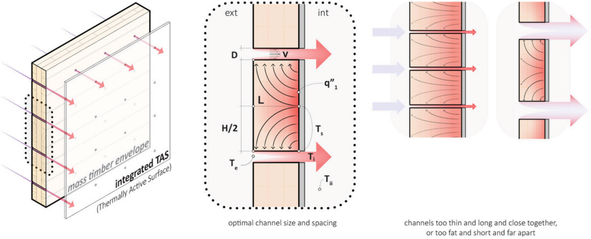
Figure A1: How to optimize the size and spacing of channels to design a mass timber panel as a heat-exchanger [31,32]
For example
The panels are meticulously perforated to ensure optimal performance, adhering to a specific ratio of H/L < 2.
where: H is the distance between two channels, L is the sheet thickness
Let the value of H/L = 1.8
L = 10 mm
That means L = 18 mm
Cite This Article
 Copyright © 2024 The Author(s). Published by Tech Science Press.
This work is licensed under a Creative Commons Attribution 4.0 International License , which permits unrestricted use, distribution, and reproduction in any medium, provided the original work is properly cited.
 Downloads
 Citation Tools