
 Submit a Paper
 Propose a Special lssue
 Open Access
ARTICLE

The Effect of Inlet Angle Structure of Concave and Convex Plate on Internal Flow Characteristics of Alkaline Electrolyzer
1 Key Laboratory of Low-Grade Energy Utilization Technologies and Systems, Ministry of Education, School of Energy and Power Engineering, Chongqing University, Chongqing, 400044, China
2 Lanzhou Lanshi Group Co., Ltd., Lanzhou, 730300, China
* Corresponding Author: Bo Hui. Email:
(This article belongs to the Special Issue: Two-phase flow heat and mass transfer in advanced energy systems)
Frontiers in Heat and Mass Transfer 2024, 22(3), 855-868. https://doi.org/10.32604/fhmt.2024.051387
Received 04 March 2024; Accepted 21 May 2024; Issue published 11 July 2024
 View Full Text
 Download PDF
Abstract
The structure of the concave-convex plates has proven to be crucial in optimizing the internal flow characteristics of the electrolyzer for hydrogen production. This paper investigates the impact of the gradual expansion angle of the inlet channel on the internal flow field of alkaline electrolyzers. The flow distribution characteristics of concave-convex plates with different inlet angle structures in the electrolytic cell is discussed. Besides, the system with internal heat source is studied. The results indicate that a moderate gradual expansion angle is beneficial for enhancing fluid uniformity. However, an excessively large gradual expansion angle may lead to adverse reflux phenomena, reducing the overall performance of the electrolytic cell.Graphic Abstract
Keywords
The implementation of carbon neutrality will enhance energy conservation and emission reduction via various approaches [1,2]. Also, it will strengthen the utilization of renewable energy [3–5]. Using the electricity generated by renewable energy to produce hydrogen is a promising way for reasonable consumption of renewable energy [6].
At present, among various hydrogen production technologies, the alkaline electrolyzer is low cost. And it is suitable for large-scale hydrogen production applications. Therefore, in recent years, many scholars have carried out a lot of research on the electrolyzer power sources [7], inputs [8], stack [9], components design, and control strategy [10] to improve the performance of alkaline electrolyzers. Additionally, researchers have explored new hybrid designs and other aspects of the electrolytic cell [11] to enhance its efficiency [12]. In alkaline electrolyzers, the main electrolytic unit’s plate is often designed with a distinctive concave-convex shape, aiming to enhance both electrolytic efficiency and flow uniformity. The multi-point electrical contact on both sides of the diaphragm establishes a complex flow path within the electrolytic unit, utilizing a specific concave-convex structure [13]. This effectively improves flow disturbance and ensures uniform distribution by directing the electrolyte through a zigzag channel formed by the spherical concave-convex structure. While the inlet channel structure of the alkaline electrolyzer has the characteristics of micro-scale and complexity, resulting in a highly intricate flow field distribution. Therefore, comprehending the impact of the inlet angle structure on the internal flow characteristics of the electrolyzer is crucial in enhancing electrolytic efficiency, reducing energy consumption, and ensuring the long-term stable operation of the equipment.
So far, the impact of alkaline electrolyzers on corrosion and tank pressure has been reported [14,15]. Simultaneously, convex-concave structures have garnered significant attention due to their outstanding heat transfer characteristics [16,17]. Additionally, they have also been recognized for their hydrodynamic properties [18,19]. Some studies have focused on the heat transfer aspects [20,21], others on the flow dynamics [22], while some have investigated both in combination [23,24]. Thus, this concave-convex structure has been extensively investigated, including the relative placement of the convex and the surface of the ball [25] and the dislocation layout [26], as well as its structural parameters such as the height of the convex ball and the depth of the concave ball, to understand their impact on fluidity. Additionally, drawing inspiration from the sphere-concave structure, various novel convex and concave designs, including square, cylindrical, ellipsoid, and teardrop shapes, have been proposed. These designs were also investigated through experimental and simulation methods to explore their flow, heat transfer, and conductivity characteristics. Zhou et al. [27] investigated the heat transfer effect of four different pit shapes under turbulent conditions. Jongmyung et al. [28] studied the flow and heat transfer of seven pit types, with the spherical structure exhibiting the best heat transfer effect. Rao et al. [29] examined flow and heat transfer performance for the teardrop-shaped pit structure. The convex-concave structure, when combined with the electrolytic cell plate, exhibits significant potential in optimizing flow distribution within the electrolytic cell. Millet et al. [30] controlled the friction loss by adjusting the diameter of the inlet channel to ensure that the water is evenly distributed in each compartment of the cell to achieve higher efficiency. Upadhyay et al. [31] discussed the influence of different numbers of inlet and outlet and different sizes of inlet and outlet on the hydrodynamic behavior of the flow field.
In the design of water electrolytic cells, electrolytic efficiency and flow uniformity are the key factors, which directly affect the efficiency and stability of the hydrogen production process. While previous studies have focused on the micro-characteristics of concave-convex structures, the influence of inlet angle structure on the overall flow characteristics has not been deeply understood. Thus, the effect of the inlet angle structure of the concave and convex plate on the internal flow characteristics of the alkaline electrolyzer is investigated in the present work. This study aims to bridge the knowledge gaps in the current research field and provide substantial guidance for future water electrolyzer design and applications.
The structure of the alkaline water electrolyzer is illustrated in Fig. 1. To simplify numerical simulation and reduce computational complexity, identical structures for the positive and negative electrode cells in the electrolytic unit is employed as the benchmark model in this study, with detailed geometrical shapes and dimensions depicted in Fig. 2. The runner structure comprises entrance, plate passage, and exit. To ensure the effective development of flow, extensions have been applied to the entrance and exit sections. Additionally, the plate channel interior features a spherical concave and convex structure. Fig. 3 presents a schematic diagram of the plate runner structure at different entrance angles (0°, 15°, 30°, and 45°). Simultaneously, to visually illustrate the variation in flow field distribution uniformity in channels with distinct structures, an assessment criterion for flow field velocity uniformity, the velocity uniformity index
where
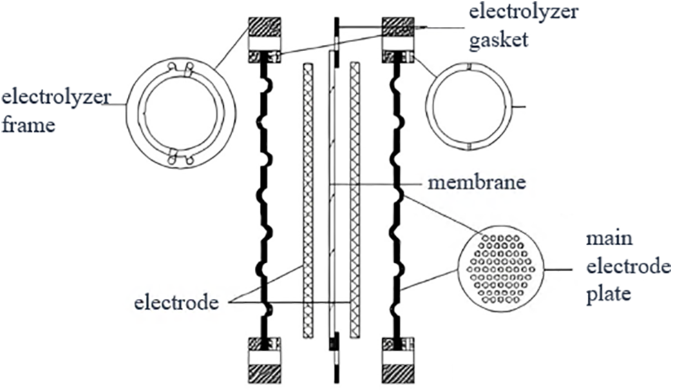
Figure 1: Structure diagram of alkaline electrolyzer
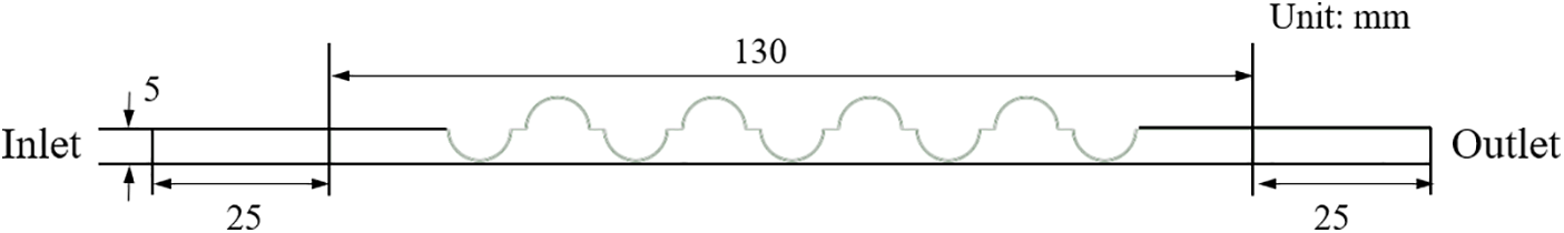
Figure 2: Structure diagram of a single electrode chamber of the electrolytic unit
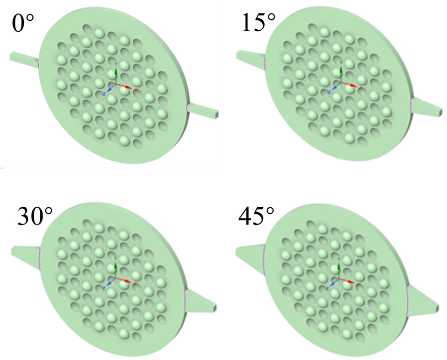
Figure 3: Schematic diagram of plate runner structure with entrance angles of 0°, 15°, 30° and 45°
2.2 Geometric Models and Meshing
To improve the efficiency of numerical simulation, the model structure and grid were simplified. As the positive and negative cell structures of the electrolytic unit are identical, a single-cell structure was chosen as the computational model, with its geometric layout and size shown in Fig. 2. The flow channel structure comprises three primary sections: entrance, plate passage, and exit. Adjustments were made to the entrance and exit to maintain flow integrity. Within the plate channel, we examined the specific design of the bump. Fig. 3 illustrates the various inlet angles of the runner and outlines the fundamental runner design.
In this study, the mesh model is processed using Ansys Meshing software, employing a combination of structured and unstructured mesh division methods. Local mesh refinement is applied at the boundary of the concave-convex structure of the flow channel. The first layer’s thickness of the boundary layer is set to 0.05 mm, with a growth factor of 1.2, and a total of 10 layers are incorporated. The grids, as finally divided, are illustrated in Fig. 4, with a total count of 2,977,574. Subsequently, numerical simulations were performed using Fluent software.
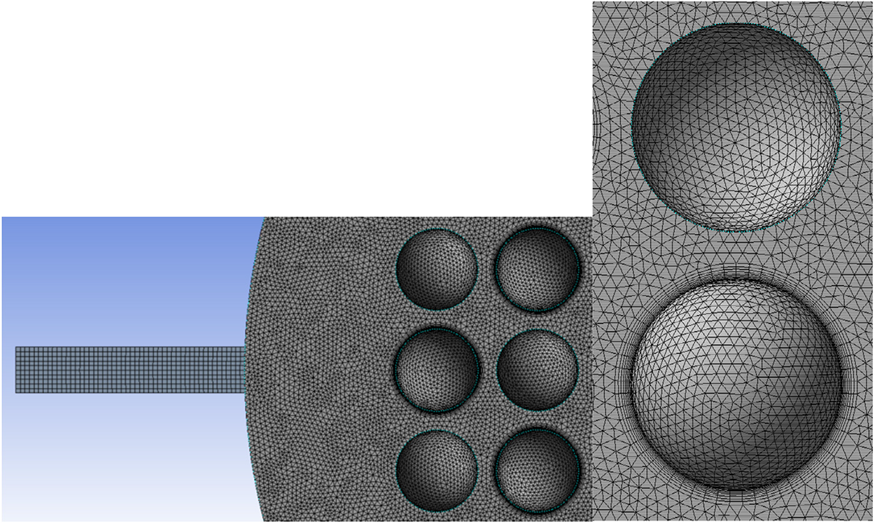
Figure 4: Grid division diagram of electrolytic unit plate channel structure
2.3.1 Turbulence Model and Related Governing Equations
The RNG k-ε turbulence model is used to simulate the low Reynolds number column group turbulent flow in the flow channel of an electrolytic cell. The governing equations are as follows:
where
2.3.2 Operating Parameters and Boundary Conditions
Alkaline water electrolyzers usually use alkaline electrolyte, such as KOH solution, NaOH solution, etc., generally injected electrolyte from the bottom of the electrolytic unit, to both replenish raw materials and provide some degree of cooling for the tank. Since this study focuses on the distribution characteristics of the flow field in fluid flow, water is chosen as the medium in this paper. The temperature is set to 300 K, with water density = 996.5 kg/m3 and viscosity = 0.00086225 Pa·s.
Boundary Conditions: The model adopts a speed inlet boundary, with the speed set to 0.0556 m/s. The pressure outlet boundary is utilized, assumed to be fully developed, and set to atmospheric pressure. Enhanced wall functions are implemented in wall simulation. For pressure-velocity coupling, the SIMPLE algorithm is selected due to its fast convergence. A second-order upwind scheme is employed for the treatment of momentum, turbulent kinetic energy, and turbulent dissipation rate. Steady-state calculations are performed. To ensure calculation accuracy, the residual differences of energy and momentum are set as 10−5, ensuring the calculation reaches a converged state.
3.1 Model Reliability Verification
In order to verify the turbulence model and calculation method, the structural parameters of the model are consistent with previous work [19], and the structure is similar to that of hydrogen production by electrolytic water [13]. The flow velocity distribution at the center section of the tank under different flow rates is calculated and compared with the simulation data and experimental data from the aforementioned two literatures, as shown in Fig. 5. As can be seen from the figure, the simulated data is generally larger than the experimental data [13], but slightly lower than that in reference [19]. This is because the PIV velocity measurement experiment used in reference [13] may have certain phenomena of light reflection and scattering in the experimental process, resulting in partial energy loss. Compared with the structured grid division method used in reference [19], the simulation data of the PIV velocity measurement experiment may have some energy loss. In this paper, a combination of structured and unstructured grid division is adopted in the process of grid division, and the average orthogonal mass is 0.78403, which affects the calculation results to a certain extent. In general, the numerical calculation method in this study can be considered reliable.
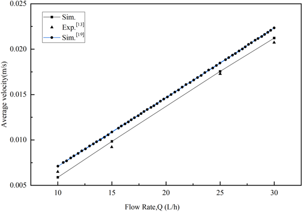
Figure 5: Comparison of simulated average flow velocity at the center section of electrolytic cell with data from literature [13,19] under different flow rates
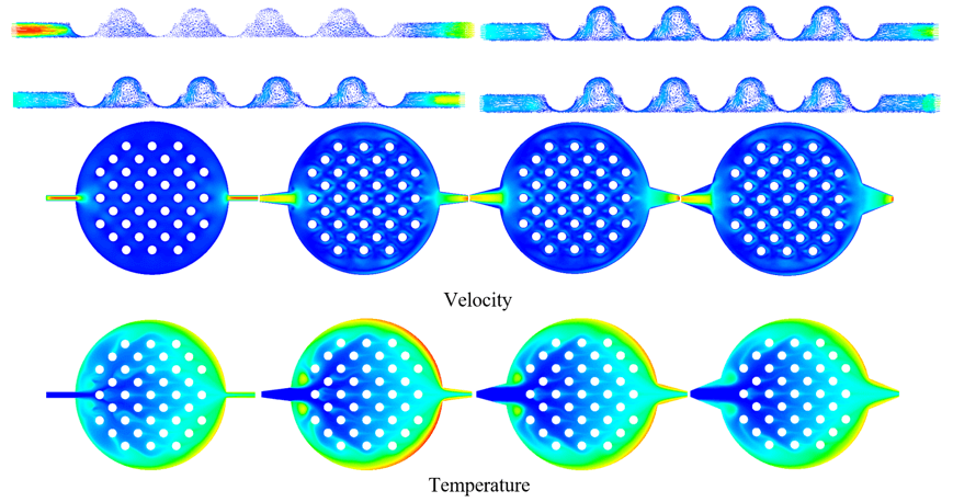
As the fluid transitions from the narrow inlet channel to the wide plate channel, the sudden increase in the flow channel section, driven by fluid inertia, can result in a concentration effect as the fluid enters the plate channel. This phenomenon leads to fluid accumulation in specific areas and may induce vortex reflux near the inlet channel, impacting fluid mixing and uniformity, thus affecting the efficiency and stability of the electrolyzer. Contour and vector diagram analysis in Fig. 6 reveal a gradual decrease in the velocity distribution gradient of the fluid in the inlet channel with an increase in the gradual expansion angle. This suggests that a larger inlet angle is conducive to reducing the inhomogeneity of fluid velocity. However, an excessively large gradual expansion angle may lead to the formation of a return zone inside the inlet channel, negatively affecting fluid flow into the plate channel and reducing the overall efficiency of the electrolyzer.
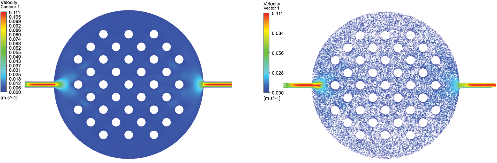

Figure 6: Velocity contour plot and vector diagram of the plate at different entrance angles
Through analysis of the velocity vector diagram in Fig. 7, which depicts the cross section of the channel, it can be observed that at the gradual expansion angle of 0°, the inlet channel velocity is concentrated, which may lead to uneven flow distribution; while at the angle of 15°, the inlet channel velocity is reduced, the outlet velocity is concentrated, and eddy currents at the ball bulge are evident. At the 30° inlet widening angle, the inlet channel velocity distribution is more uniform, the outlet velocity is relatively large, and the eddy current degree at the ball convex is similar to that at 15°. At 45° inlet angle, the inlet channel no longer shows velocity concentration, the outlet channel speed concentration decreases, and the eddy current at the ball convex is weak. This series of observations shows that different inlet angles cause significant changes in the flow field inside the water electrolyzer. With the increase in the gradual expansion angle, the flow presents a more uniform distribution, which may be attributed to the gradual reduction of the flow disturbance caused by the angle change, making the velocity more stable in the channel. However, this trend is accompanied by some key effects that require further analysis. First, we observe that the exit velocity decreases as the angle of gradual expansion increases. This may result in a more uniform velocity distribution due to the larger gradual expansion angle, but it restricts the maximum velocity to some extent, making us need to find a balance point between the flow uniformity and the exit velocity. Secondly, the change in vortex characteristics is also an aspect worthy of attention. When the angle of gradual expansion is low, the eddy current at the convex of the ball is relatively weak, but with the increase of gradual expansion angle, the eddy current is gradually strengthened. This suggests that adjusting the gradual expansion angle can directly influence the degree of flow field disturbance, and may have a significant effect on the mass and heat transfer performance of the electrolytic cell. In summary, the influence of different inlet angles on the flow field in water electrolyzer is complex and varied, involving flow uniformity, outlet velocity and eddy current characteristics.
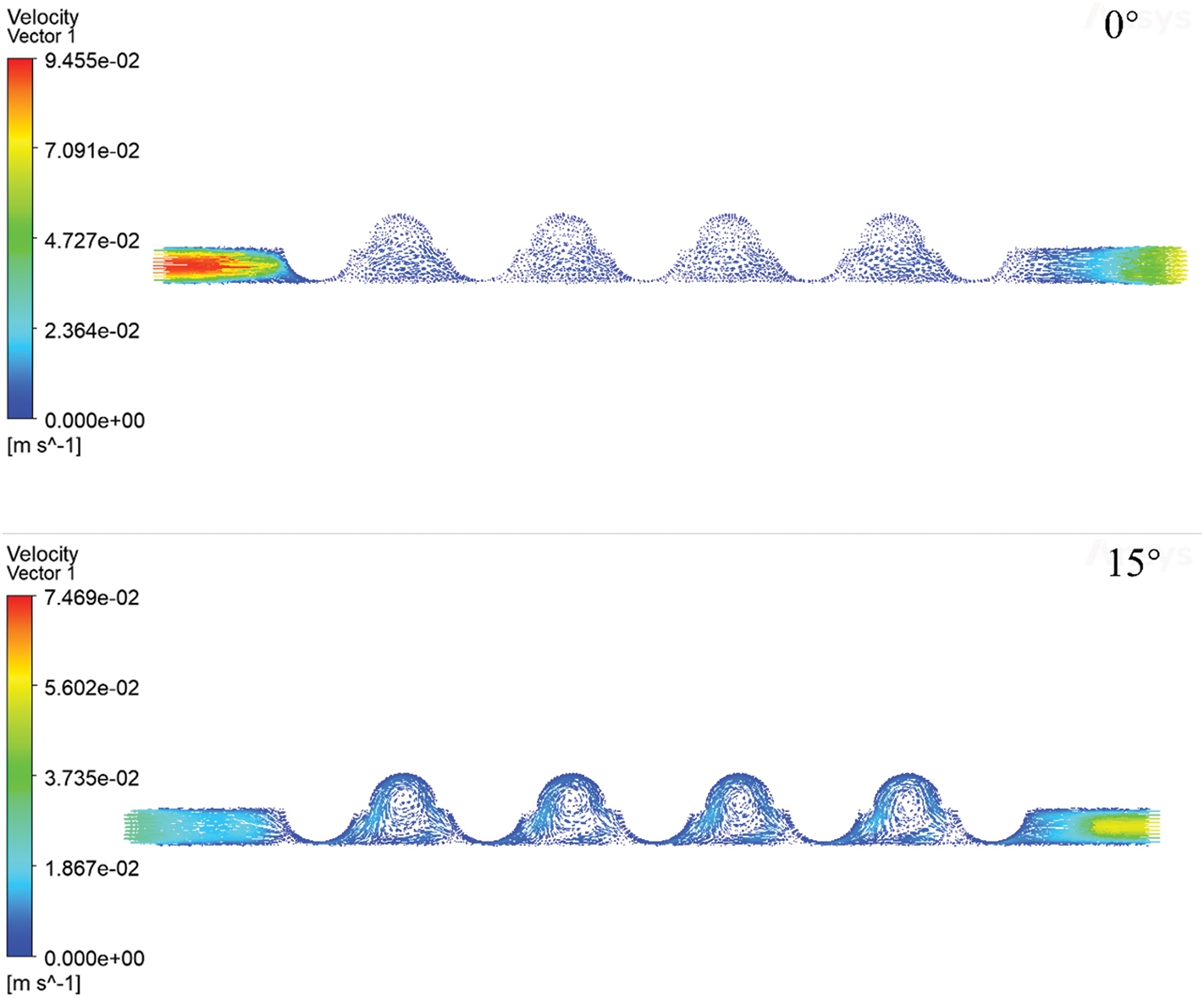
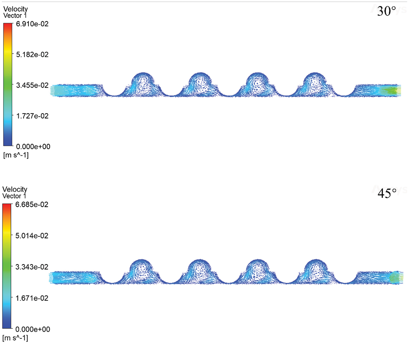
Figure 7: Velocity vector diagram distribution of channel cross section
To further investigating the heat and mass transfer of the fluid within the channel of the corrugated plate, here introduces an internal heat source by adding an energy term to the main plate region. This energy source simulates the heat generated during the electrolysis process of water. By observing the temperature field distribution, an internal heat source of 600 watts is incorporated. Fig. 8 presents contour plots of the temperature distribution on the corrugated plate at different inlet angles. It is evident that there are two distinct regions on both sides of the inlet channel. These regions may be attributed to vortices when the fluid enters the circular corrugated plate through the inlet channel. The local temperature rises due to resistance and turbulence. Additionally, a high-temperature layer consistently exists on the right edge of the main plate, which is results of the temperature boundary layer. The temperature boundary layer refers to the region where the fluid experiences temperature changes near a solid surface due to heat transfer. The presence of high temperatures on the right edge of the main plate can be attributed to the sudden reduction of the flow channel cross-section as the fluid exits the plate, leading to inadequate outflow and accumulation on the right side. From the velocity contour plot and vector diagram of the plate at different entrance angles in Fig. 6, we can also find that there is a flow boundary layer at the bottom of the outlet of the main plate channel, which explains the objective cause of the temperature boundary layer. At the same time, considering that our simulation does not take into account the existence of external flow fields, the heat stored in the plate is partially unable to dissipate to the environment, which also exacerbates this phenomenon. Furthermore, it is observed that as the inlet angle increases, temperature non-uniformity becomes evident in the inlet channel, further confirming that excessive inlet angles are not advisable.
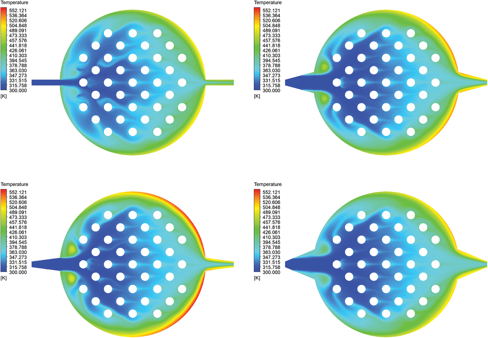
Figure 8: Temperature contour plot of the plate at different entrance angles
Fig. 9 shows the
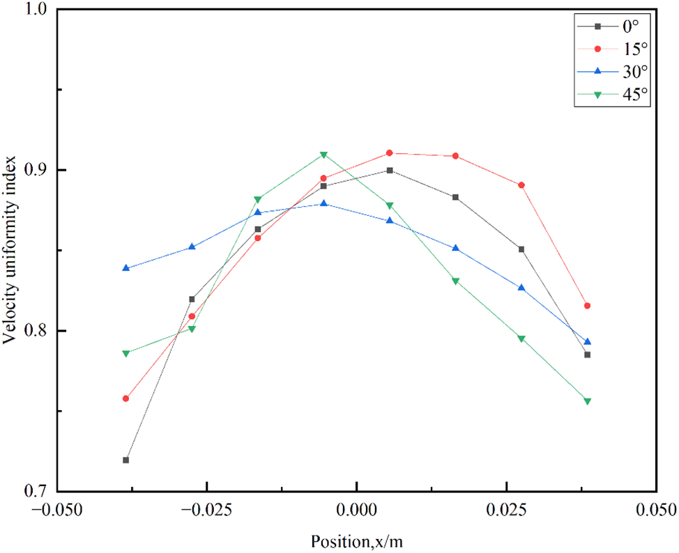
Figure 9: Exponential distribution of velocity uniformity along the channel
Thus, it can be concluded that the inlet angle is a parameter requiring careful consideration and optimization. While appropriate scaling enhances fluid uniformity, excessive scaling may introduce undesirable hydrodynamic effects. Therefore, in the design and optimization of the gradual expansion angle, a comprehensive consideration of fluid dynamics, efficiency, and the desired fluid uniformity is necessary to achieve optimal cell performance.
In this study, we conducted a comprehensive investigation of the internal flow characteristics of alkaline electrolyzers. The key findings of our study are summarized as follows.
As a key structural parameter of an electrolyzer, the inlet angle plays an important role in alkaline electrolyzer performance. By comparing different angles of gradual enlargement, we found that moderate gradual enlargement can indeed improve the uniform distribution of fluid. Generally, angles between 15° and 30° perform better. A large angle of entrance may lead to backflow phenomena and other adverse hydrodynamic effects, which reduce the overall performance of the electrolyzer. Therefore, in practical applications, the inlet angle and other design parameters need to be carefully considered.
It is worth noting that as a complex engineering system, the performance of alkaline electrolyzers is affected by many factors. The research in this paper also has some limitations. The assumptions in the simulation model are too simplified, for example, the variable property parameters of the simulated fluid are not considered. In addition to the inlet angle structure, other factors such as the rheological properties of the electrolyte, the choice of electrode materials, and operating conditions may have an impact on the overall performance of the electrolyzer. Therefore, further optimized designs and structures will be discussed based on the experiments in our future works.
Acknowledgement: The authors wish to acknowledge Prof. QIBIN LI (guest editor) and anonymous reviewers.
Funding Statement: This research was supported by Science and Technology Projects of Gansu, China (No. 22ZD6GA014).
Author Contributions: The authors confirm contribution to the paper as follows: study conception and design: Bo Hui, Shengneng Zhu; data collection: Bo Hui; analysis and interpretation of results: Sijun Su, Wenjuan Li; draft manuscript preparation: Shengneng Zhu, Wenjuan Li. All authors reviewed the results and approved the final version of the manuscript.
Availability of Data and Materials: Data will be made available on request.
Conflicts of Interest: The authors declare that they have no known competing financial interests or personal relationships that could have appeared to influence the work reported in this paper.
References
1. Project Team on the Strategy and Pathway for Peaked Carbon Emissions and Carbon Neutrality (2021). Analysis of a peaked carbon emission pathway in China toward carbon neutrality. Engineering, 7(12), 1673–1677. https://doi.org/10.1016/j.eng.2021.10.003 [Google Scholar] [CrossRef]
2. Wang, S., Tang, J., Liu, C., Li, Q., Sun, Z. et al. (2024). Techno-economic-environmental analysis and fluid selection of transcritical organic Rankine cycle with zeotropic mixtures. Journal of Cleaner Production, 436(9–10), 140690. https://doi.org/10.1016/j.jclepro.2024.140690 [Google Scholar] [CrossRef]
3. Wang, P., Li, Q., Wang, S., He, C., Wu, C. (2024). Off-design performance evaluation of thermally integrated pumped thermal electricity storage systems with solar energy. Energy Conversion and Management, 301, 118001. https://doi.org/10.1016/j.enconman.2023.118001 [Google Scholar] [CrossRef]
4. Tang, J., Li, Q., Wang, S., Yu, H. (2023). Thermo-economic optimization and comparative analysis of different organic flash cycles for the supercritical CO2 recompression Brayton cycle waste heat recovery. Energy, 278(1), 128002. https://doi.org/10.1016/j.energy.2023.128002 [Google Scholar] [CrossRef]
5. Wang, X., Li, X., Li, Q., Liu, L., Liu, C. et al. (2020). Performance of a solar thermal power plant with direct air-cooled supercritical carbon dioxide Brayton cycle under off-design conditions. Applied Energy, 261(8), 114359. https://doi.org/10.1016/j.apenergy.2019.114359 [Google Scholar] [CrossRef]
6. Cartaxo, M., Fernandes, J., Gomes, M., Pinho, H., Nunes, V. et al. (2021). Hydrogen production via wastewater electrolysis-an integrated approach review. 6th International Conference on Smart City Applications, Safranbolu, TURKEY. [Google Scholar]
7. Sakas, G., Ibáñez-Rioja, A., Pöyhönen, S., Kosonen, A., Ruuskanen, V. et al. (2024). Influence of shunt currents in industrial-scale alkaline water electrolyzer plants. Renewable Energy, 225(2), 120266. https://doi.org/10.1016/j.renene.2024.120266 [Google Scholar] [CrossRef]
8. Cheng, H., Xia, Y., Hu, Z., Wei, W. (2024). Optimum pulse electrolysis for efficiency enhancement of hydrogen production by alkaline water electrolyzers. Applied Energy, 358(1), 122510. https://doi.org/10.1016/j.apenergy.2023.122510 [Google Scholar] [CrossRef]
9. Huang, C., Zong, Y., You, S., Træholt, C. (2022). Economic model predictive control for multi-energy system considering hydrogen-thermal-electric dynamics and waste heat recovery of MW-level alkaline electrolyzer. Energy Conversion and Management, 265, 115697. https://doi.org/10.1016/j.enconman.2022.115697 [Google Scholar] [CrossRef]
10. Cheng, H. R., Xia, Y. H., Wei, W., Zhou, Y. Z., Zhao, B. et al. (2023). Safety and efficiency problems of hydrogen production from alkaline water electrolyzers driven by renewable energy sources. International Journal of Hydrogen Energy, 54, 700–712. https://doi.org/10.1016/j.ijhydene.2023.08.324 [Google Scholar] [CrossRef]
11. Ding, S., Guo, B., Hu, S., Gu, J., Yang, F. et al. (2022). Analysis of the effect of characteristic parameters and operating conditions on exergy efficiency of alkaline water electrolyzer. Journal of Power Sources, 537(7), 231532. https://doi.org/10.1016/j.jpowsour.2022.231532 [Google Scholar] [CrossRef]
12. Makhsoos, A., Kandidayeni, M., Pollet, B. G., Boulon, L. (2023). A perspective on increasing the efficiency of proton exchange membrane water electrolyzers-a review. International Journal of Hydrogen Energy, 48(41), 15341–15370. https://doi.org/10.1016/j.ijhydene.2023.01.048 [Google Scholar] [CrossRef]
13. Li, L., Zhang, J., Zhou, K. (2009). Numerical simulation analysis of single-phase flow field in micro-channel of square column group of electrolytic water oxygen-making tank. Aerospace Medicine and Medical Engineering, 22(1), 22–26. [Google Scholar]
14. Zhou, J., Wu, W. (2006). Study on the corrosion mechanism of the electrode plate of the pressure filter electrolyzer for hydrogen production. Naval Science and Technology, 2, 34–37. [Google Scholar]
15. Prestat, M. (2023). Corrosion of structural components of proton exchange membrane water electrolyzer anodes: A review. Journal of Power Sources, 556, 232469. https://doi.org/10.1016/j.jpowsour.2022.232469 [Google Scholar] [CrossRef]
16. Norikazu, S., Masahide, I., Kaneda, K., Horinouchi, N., Ota, A. et al. (2017). Numerical investigation of the effect of Prandtl number on heat transfer in a dimpled-channel flow. International Journal of Heat and Fluid Flow, 68(6), 139–150. https://doi.org/10.1016/j.ijheatfluidflow.2017.10.005 [Google Scholar] [CrossRef]
17. Isaev, S., Leontiev, A., Milman, O., Popov, I., Sudakov, A. et al. (2019). Influence of the depth of single-row oval-trench dimples inclined to laminar air flow on heat transfer enhancement in a narrow micro-channel. International Journal of Heat and Mass Transfer, 134(10), 338–358. https://doi.org/10.1016/j.ijheatmasstransfer.2018.12.175 [Google Scholar] [CrossRef]
18. Duan, X., Xiang, X., Chen, J., Zhou, A., Xiao, J. et al. (2024). Numerical simulation and multi-objective optimization on flow performance of novel alkaline water electrolyzer. International Journal of Hydrogen Energy, 55(36), 1505–1513. https://doi.org/10.1016/j.ijhydene.2023.11.176 [Google Scholar] [CrossRef]
19. Wang, J., Li, J., Zou, S., He, X., Wan, J. et al. (2020). Simulation on flow characteristics of spherical convex-concave structure in microchannel of ressurefiltered water electrolyzer. The Chinese Journal of Process Engineering, 20(3), 294–301 (In Chinese). [Google Scholar]
20. Xie, S., Liang, Z., Zhang, L., Wang, Y. et al. (2018). A numerical study on heat transfer enhancement and flow structure in enhanced tube with cross ellipsoidal dimples. International Journal of Heat and Mass Transfer, 125(20), 434–444. https://doi.org/10.1016/j.ijheatmasstransfer.2018.04.106 [Google Scholar] [CrossRef]
21. Toygun, D., Orhan, K., Veysel, O. (2019). Heat transfer performance and flow characteristic in enhanced tube with the trapezoidal dimples. International Communications in Heat and Mass Transfer, 108(6), 104299. https://doi.org/10.1016/j.icheatmasstransfer.2019.104299 [Google Scholar] [CrossRef]
22. Xie, S., Liang, Z., Zhang, J., Zhang, L., Wang, Y. L. et al. (2019). Numerical investigation on flow and heat transfer in dimpled tube with teardrop dimples. International Journal of Heat and Mass Transfer, 131(6), 713–723. https://doi.org/10.1016/j.ijheatmasstransfer.2018.11.112 [Google Scholar] [CrossRef]
23. Jae, S., Myunggeun, J., Gap Park, Y., Yeong Ha, M. (2019). Numerical study on the flow and heat transfer characteristics in a dimple cooling channel with a wedge-shaped vortex generator. International Journal of Heat and Mass Transfer, 136(12), 1064–1078. https://doi.org/10.1016/j.ijheatmasstransfer.2019.03.072 [Google Scholar] [CrossRef]
24. Du, W., Luo, L., Wang, S., Zhang, X. (2019). Flow structure and heat transfer characteristics in a 90-deg turned pin fined duct with different dimple/protrusion depths. Applied Thermal Engineering, 146(1), 826–842. https://doi.org/10.1016/j.applthermaleng.2018.10.052 [Google Scholar] [CrossRef]
25. Elyyan, M., Rozati, A., Tafti, D. K. (2008). Investigation of dimpled fins for heat transfer enhancement in compact heat exchangers. International Journal of Heat and Mass Transfer, 51(11), 2950–2966. https://doi.org/10.1016/j.ijheatmasstransfer.2007.09.013 [Google Scholar] [CrossRef]
26. Hwang, S., Cho, H., Kwon, H. (2010). Local heat transfer and thermal performance on periodically dimple-protrusion patterned walls for compact heat exchangers. Energy, 35(12), 5357–5364. https://doi.org/10.1016/j.energy.2010.07.022 [Google Scholar] [CrossRef]
27. Zhou, F., Acharya, S. (2009). Experimental and computational study of heat/mass transfer and flow structure for four dimple shapes in a square internal passage. Journal of Turbomachinery, 134(6), 939–953. [Google Scholar]
28. Jongmyung, P., Ligrani, P. M. (2005). Numerical predictions of heat transfer and fluid flow characteristics for seven different dimpled surfaces in a channel. Numerical Heat Transfer Applications, 47(3), 209–232. https://doi.org/10.1080/10407780590886304 [Google Scholar] [CrossRef]
29. Rao, Y., Feng, Y., Li, B., Weigand, B. (2014). Experimental and numerical study of heat transfer and flow friction in channels with dimples of different shapes. Journal of Heat Transfer, 134(12), 723–732. [Google Scholar]
30. Millet, P., Andolfatto, F., Durand, R. (1996). Design and performance of a solid polymer electrolyte water electrolyzer. International Journal of Hydrogen Energy, 21(2), 87–93. [Google Scholar]
31. Upadhyay, M., Lee, S., Jung, S., Choi, Y., Moon, S. et al. (2020). Systematic assessment of the anode flow field hydrodynamics in a new circular PEM water electrolyser. International Journal of Hydrogen Energy, 45(41), 20765–20775. https://doi.org/10.1016/j.ijhydene.2020.05.164 [Google Scholar] [CrossRef]
32. Weltens, H., Bressler, H., Terres, F., Neumaier, H., Rammoser, D. (1993). Optimisation of catalytic converter gas flow distribution by CFD prediction. SAE Technical Paper. https://doi.org/10.4271/930780 [Google Scholar] [CrossRef]
Cite This Article
 Copyright © 2024 The Author(s). Published by Tech Science Press.
This work is licensed under a Creative Commons Attribution 4.0 International License , which permits unrestricted use, distribution, and reproduction in any medium, provided the original work is properly cited.
 Downloads
 Citation Tools