
 Submit a Paper
 Propose a Special lssue
 Open Access
ARTICLE

Numerical Investigations on Fluid Flow and Heat Transfer Characteristics of an Ultra-Thin Heat Pipe with Separated Wick Structures
1 Division of Industrial Fundamentals, Faculty of Advanced Science and Technology, Kumamoto University, Kumamoto, 860-8555, Japan
2 Department of Mechanical and Mathematical Engineering, Graduate School of Science and Technology, Kumamoto University, Kumamoto, 860-8555, Japan
* Corresponding Author: Yasushi Koito. Email:
Frontiers in Heat and Mass Transfer 2024, 22(3), 869-887. https://doi.org/10.32604/fhmt.2024.050910
Received 22 February 2024; Accepted 15 May 2024; Issue published 11 July 2024
 View Full Text
 Download PDF
Abstract
Thermal and fluid-flow characteristics were numerically analyzed for ultra-thin heat pipes. Many studies have been conducted for ultra-thin heat pipes with a centered wick structure, but this study focused on separated wick structures to increase the evaporation/condensation surface areas within the heat pipe and to reduce the concentration of heat flux within the wick structure. A mathematical heat-pipe model was made in the three-dimensional coordinate system, and the model consisted of three regions: a vapor channel, liquid-wick, and container wall regions. The conservation equations for mass, momentum, and energy were solved numerically with boundary conditions by using a code developed by one of the authors. The numerical results with the separated wick structures were compared with those with the centered, which confirmed the effectiveness of the separation of the wick structure. However, the effectiveness of the separation was affected by the position of the separated wick structure. A simple equation was presented to determine the optimum position of the separated wick structures. Numerical analyses were also conducted when the width of the heat pipe was increased with the cooled section, which clarified that the increase in the cooled-section width with the addition of wick structures was more effective than the increase in the cooled-section length. A 44% reduction in the total temperature difference of the heat pipe was obtained under the present numerical conditions. Furthermore, a comparison was made between experimental results and numerical results.Keywords
Nomenclature
| A | Area (m2) |
| b | Width (mm, m) |
| C | Thermal conductance (W/K) |
| cp | Specific heat at constant pressure (J/(kg·K)) |
| d | Hydraulic diameter (m) |
| h | Height (mm, m) |
| hfg | Latent heat (J/kg) |
| K | Permeability (m2) |
| l | Length (mm, m) |
| n | Coordinate normal to boundary surface (m) |
| p | Pressure (Pa) |
| Q | Volume flow rate (m3/s), heat input (W) |
| q | Heat flux (W/m2) |
| Rg | Gas constant (J/(kg·K)) |
| T | Temperature (°C) |
| u, v, w | x, y, z-direction velocities (m/s) |
| V | Velocity vector (= (u, v, w)) (m/s) |
| x, y, z | Rectangular coordinates (mm, m) |
| Greek Symbols | |
| Δp | Pressure difference (Pa, kPa) |
| ΔT | Temperature difference (°C) |
| δ | Thickness (mm, m) |
| ε | Porosity (–) |
| η | Ratio defined by Eq. (18) (–) |
| λ | Thermal conductivity (W/(m·K)) |
| μ | Viscosity (Pa·s) |
| ρ | Density (kg/m3) |
| Subscripts | |
| a | Adiabatic |
| ave | Average |
| c | Cooled |
| cal | Calculated |
| cen | Centered |
| eff | Effective |
| exp | Experimental |
| f | Cooling fluid |
| h | Heated |
| i | Vapor-wick interface |
| l | Liquid-wick region |
| ref | Reference |
| sep | Separated |
| t | Total |
| v | Vapor channel region |
| v1, v2, v3 | Ch. 1, Ch. 2, Ch. 3 in vapor channel region |
| w | Container wall region |
In the past ten years, a large number of studies have been conducted to develop very thin heat pipes. This target is recently called ultra-thin heat pipe, and the research background is a thermal issue in thin electronic devices such as smartphones [1–3], wearable devices [4–6], and ultra-slim laptop computers [7]. Various types of ultra-thin heat pipes have been published; they can be categorized as flattened-pipe type [8,9], sandwiched-plate type [10,11], and loop type [12,13]. A manufacturing process of the flattened type was shown by Zhou et al. [14], and that of sandwiched type was shown by Chen et al. [15]. Chen et al. [13] employed a novel print wick structuring process to fabricate the loop type. The separation of vapor flow and liquid flow paths is a unique feature of the loop type. Among them, the flattened type is simplest in structure, and thus has the advantage of being easy to manufacture.
In the flattened type, a wick structure is often placed at the center of a vapor flow channel [1,16]. Literature reviews on this kind of heat pipe were already presented in the authors’ previous papers [17,18]. In addition, recently, Yi et al. proposed a new type of segmented wick structure [19] and a novel double-layer wick structure [20] for the performance increase of ultra-thin heat pipes. Fig. 1a shows a cross-section of a flattened centered-wick heat pipe. Ultra-thin heat pipes with a thin wick sheet under the vapor flow path were also developed [21,22], but this structure reduces the height of the vapor flow path, and thus has a concern regarding an increase in a vapor pressure drop. The centered wick structure has been employed so that the wick structure does not lower the height of the vapor flow path. However, because the centered wick structure is very thin and is sandwiched between the upper and lower wall of the container, the evaporation and condensation surface areas are essentially very small. In addition, different from conventional heat pipes [23–25], a centered-wick heat pipe leaves vapor-wick-wall contact lines, which causes the concentration of heat flux within the wick structure [18]. The reduction is needed for further improvement of the thermal performance of the centered-wick heat pipe.

Figure 1: Cross-sections of the ultra-thin flattened heat pipes
It is expected that the thermal performance of a heat pipe would be increased by increasing the evaporation/condensation surface areas. Ji et al. [26] proposed a vapor chamber with an extended condensation area, and experimentally confirmed the effectiveness of this design. Wu et al. [27] showed that the thermal performance of a loop heat pipe increased with increasing the wick evaporation area. It is thought that these results can be applied to an ultra-thin flattened centered-wick heat pipe. Thus, this study proposed separated wick structures as shown in Fig. 1b to increase the evaporation/condensation surface areas within the heat pipe and to reduce the concentration of heat flux within the wick structure. When the centered wick structure is divided into two, the vapor-wick interface area doubles while keeping the same cross-sectional area of the wick structure. Recently, Ming et al. [28] placed two wick bundles separately within an ultra-thin flattened heat pipe, and conducted experiments on the heat transfer characteristics of the heat pipe. Experimental results were compared for the centered and separated wick structures. However, a difference in the heat transfer process between the two cases has not been deeply discussed. Therefore, more discussion is necessary regarding the effectiveness of the separated wick structures.
In this study, therefore, numerical analyses were conducted on the fluid flow and heat transfer characteristics within the heat pipe with separated wick structures. A computational domain is also shown in Fig. 1b, where a symmetric condition was used at the center. A mathematical model of the centered-wick heat pipe developed by one of the authors [18] was extended to consider the separated wick structures, and the numerical results of velocity, pressure, and temperature distributions within the heat pipe were obtained. A comparative study was conducted between the heat pipes with centered and separated wick structures. Effect of separated wick position on the heat transfer characteristics of the heat pipe was described. Discussion was made when the heat-pipe width was increased with the cooled section. Furthermore, an extended experiment was also conducted, and a comparison was made between the experimental results and numerical results.
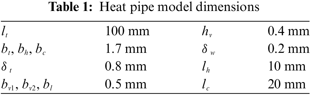
Fig. 2 shows a mathematical model of the separated-wick heat pipe. Numerical analyses were conducted with a symmetric condition in the rectangular coordinates. Because this model was based on the previous model [18], only the main points of the mathematical model and numerical calculation procedure are described here to avoid duplication. Fig. 2a is the whole view of the model, and the x-z cross-section is shown in Fig. 2b. The model had three regions of a vapor channel, liquid-wick, and container wall with heated and cooled sections on the bottom. Note that the model had walls at both ends of y = 0 and y = lt, but the former is not drawn in the figure to show the inside. The three regions were same in length, which was represented by lt. The lengths of the heated and cooled sections were lh and lc, respectively, and their widths were equal to the width (bt) of the heat pipe model. The thickness of the liquid-wick region and the height (hv) of the vapor channel region was the same. Different from the previous model [18], the vapor channel region had two sub-regions of Ch. 1 and Ch. 2 as shown in the figure. The widths of Ch. 1 and Ch. 2 were represented by bv1 and bv2, respectively, and the width of the liquid-wick region was bl. The thickness of the container wall region was δw. The total width (bt) and total thickness (δt) of the mode are expressed respectively by

Figure 2: Mathematical model of the heat pipe with separated wick structures
Eqs. (3)–(9) represent the governing equations to obtain the velocity, pressure, and temperature distributions. The conservation equations for mass, momentum, and energy were given for the three regions, respectively.
For the vapor channel region:
For the liquid-wick region:
For the container wall region:
The governing equations are expressed by using the velocity vector (V). Darcy’s law and the effective thermal conductivity (λeff) were used in the liquid-wick region.
The heat flux (q) at the heated section, the cooling fluid temperature (Tf), and the thermal conductance (C) between the cooled section and cooling fluid were given, and the boundary conditions for the heated and cooled sections are represented respectively by
Except for these two sections, the adiabatic condition (
Eqs. (12)–(14) are the boundary conditions at the vapor-wall, wick-wall, and vapor-wick interfaces, respectively.
Eq. (14) was obtained from the Clausius-Clapeyron equation.
Eq. (15) is the energy balance at the vapor-wick interface.
By applying Eq. (15) to both the vapor-wick interfaces on Ch. 1 and Ch. 2 sides, uv and ul were given at the vapor-wick interfaces as the boundary conditions. The velocities perpendicular to the vapor-wall and wick-wall interfaces were set to zero. A non-slip condition was applied to the vapor-wall, wick-wall, and vapor-wick interfaces. A symmetric condition was applied to the y-z surface at x = 0.
Although the present mathematical model had the three regions, numerical calculations were conducted as a single domain problem [29]. That is, Eqs. (3) and (6) were transformed into a general form of the equation of continuity. A general form of the equation of motion was obtained from Eqs. (4) and (7), and a general form of the equation of energy was obtained from Eqs. (5), (8), and (9). The generalized equations were discretized by using the control volume method, and calculations were proceeded according to the SIMPLE algorithm [30]. Eqs. (12)–(15) were applied within the single domain, and calculations were iterated until the agreement between the heat transfer rates at the heated and cooled sections became less than 1.0%. An original code developed by one of the authors was used to obtained numerical results. The temperature dependence of the physical properties was considered. Based on the mesh size test [18], 51 (x-direction) × 56 (y-direction) × 54 (z-direction) mesh was generated in the calculation domain. Non-uniform mesh was employed to reduce calculation load.
The model dimensions were set as shown in Table 1 based on the actual heat pipe in literature [1]. In addition, same as the previous paper [18], the wick structure was sintered copper powders (ε = 0.40, λeff = 6.01 W/(m·K), K = 9.00 × 10⁻¹³ m2), and the working fluid was water. The container material was copper. Calculations were conducted under q = 1.76 × 10⁵ W/m2, Tf = 25.0°C, and C = 0.157 W/K. The corresponding heat transport rate of the heat pipe model was 3.0 W. It is obvious that numerical results are influenced by the heating rate (q), cooling temperature (Tf), and vapor channel height (hv). However, because their influences were already discussed in the authors’ previous paper [18], those three parameters were not changed in the present numerical analyses.
3.1 Comparison between Centered and Separated Wick Structures
The numerical results for the heat pipe with separated wick structures were compared with the case of a centered wick structure. Figs. 3 and 4 show the comparisons regarding the velocity and pressure distributions, respectively, on the x-y cross-section at the center of the vapor channel region (z = 0.4 mm). Numerical calculations for the centered-wick heat pipe were conducted with bv1 = 0 mm and bv2 = 1.0 mm; the other numerical conditions were the same as those for the separated-wick heat pipe. Based on lh = 10 mm and lc = 20 mm, the model can be divided into an evaporator, adiabatic, and condenser sections as shown in Fig. 3, which confirmed the vapor flows from the evaporator to the condenser for both the cases of centered and separated wick structures. In an ultra-thin heat pipe, because of a much thinner vapor flow channel, the vapor velocity is much higher than the case of a conventional normal-size heat pipe [18]. Thus, the maximum vapor velocity was 67.4 m/s for the centered wick structure, and those were 81.2 m/s in Ch. 1 and 71.3 m/s in Ch. 2 for the separated wick structures. Although the widths of Ch. 1 and Ch. 2 were the same, the maximum velocity in Ch. 1 was slightly higher than that in Ch. 2. The non-slip condition was used on both the sides (x = bv1 + bl and x = bv1 + bl + bv2) in Ch. 2, while that was applied only to the one side (x = bv1) in Ch. 1. The symmetric condition was applied at x = 0 mm, which increased the vapor velocity in Ch. 1. Moreover, the non-slip condition increased the vapor pressure drop; the vapor pressure difference between the ends of the vapor flow channel in Ch. 2 (4.2 kPa) was slightly larger than that in Ch. 1 (3.6 kPa). The vapor pressure difference for the centered wick structure was 3.1 kPa. Although differences were found in the three vapor pressure differences, those were very small because the total cross-sectional areas of the vapor flow channels for the centered and separated wick structures were the same, and Ch. 1 and Ch. 2 for the separated wick structures had the same width.

Figure 3: Vapor velocity in the vapor flow channel

Figure 4: Vapor pressure in the vapor flow channel
Fig. 5 compares the temperature distributions for the centered and separated wick structures. The temperature distributions on the outer surface of the heat pipe are shown under the same numerical conditions as those in Figs. 3 and 4. An enlarged view of the x-z cross-section at y = 0 mm is also shown with solid and dashed lines that indicate the vapor channel and liquid-wick regions, respectively. Due to the evaporation, lower temperatures were confirmed near the vapor-wick interfaces. Because the same value of thermal conductance was given in Eq. (11), the temperature distributions at the cooled section (80 mm ≤ y ≤ 100 mm) were almost the same between the centered and separated wick structures. However, at the heated section (0 mm ≤ y ≤ 10 mm), a difference was clearly found between the two cases. In case of the separated wick structures, evaporation and condensation occurred on their both sides, which implies that the evaporation/condensation surface areas for the separated wick structures were double the areas for the centered wick structure. Because of this, the heated-section temperatures for the separated wick structures were lower than those for the centered wick structure. By using the average temperatures at the heated (Th,ave) and cooled (Tc,ave) sections, the total temperature difference (ΔTt) of the heat pipe was evaluated by

Figure 5: Temperature distributions of the heat pipe
The ΔTt values for the centered and separated wick structures were 18.4°C and 13.9°C, respectively.
The heat flux (qi) at the vapor-wick interface was evaluated by
where subscript i implies the vapor-wick interface. From the above-mentioned temperature distributions, the heat flux distributions were calculated, and the comparisons are shown in Fig. 6 for the centered and separated wick structures. Since the separated wick structure had two vapor-wick interfaces, the heat flux distribution on the Ch. 1 side is shown in Fig. 6b and that on the Ch. 2 side is in Fig. 6c. Owing to the difference in heat-flow direction, the heat flux was positive at evaporation interface while negative at condensation interface in Figs. 6a and 6c. The positive and negative signs of the heat flux were opposite in Fig. 6b. The vapor-wick-wall contact lines located at z = 0.2 and 0.6 mm. As mentioned in the authors’ previous paper [18], the concentration of heat flux was found within the wick structure near the vapor-wick-wall contact lines. Although only the bottom of the heat pipe was heated and cooled, the concentration of heat flux was found at the upper part of the vapor-wick interface as well as at the lower part because of the conductive heat transfer through the container wall region. The magnitudes of the concentrated heat fluxes were almost the same at the lower and upper parts of the vapor-wick interface. The comparison between the three heat flux distributions confirmed that the heat flux concentration for the separated wick structures was smaller than that for the centered wick structure, which implies that the heat flux concentration was reduced by the separation of the wick structure.

Figure 6: Heat flux distributions on the vapor-wick interfaces
By using the total temperature differences for the centered (ΔTt,cen) and separated (ΔTt,sep) wick structures, the following ratio (η) was introduced to evaluate the effectiveness of the separation of the wick structure:
where ΔTt,cen and ΔTt,sep at the same q were used to calculate η. The numerator of Eq. (18) represents a reduction in ΔTt due to the wick separation. By changing bv1 and bv2, that is, the position of the separated wick structure, ΔTt,sep was calculated and then η was obtained as shown in Fig. 7. Except for bv1 and bv2, the numerical conditions were the same as those in Figs. 3 and 4. Note that, because of Eq. (1) with bt = 1.7 mm, bl = 0.5 mm, and δw = 0.2 mm, bv1 and bv2 were in bv1 + bv2 = 1.0 mm. In addition, the vapor pressure differences between the ends of the vapor flow channel for Ch. 1 (Δpv1) and Ch. 2 (Δpv2) are also shown in Fig. 7. η was affected by the position of the separated wick structure. When bv1 became smaller, Δpv1 increased owing to the decrease in the cross-sectional area of Ch. 1. Because of the saturated condition within the heat pipe, which was expressed as Eq. (14), the temperature difference between the ends of Ch. 1 was increased by the increase in Δpv1. Thus, η decreased with decreasing bv1 for bv1 ≤ 0.4 mm. On the other hand, because of the increase in Δpv2, η decreased with increasing bv1 for bv1 ≥ 0.5 mm. η was maximum between bv1 = 0.4 mm and 0.5 mm, where Δpv1 was almost equal to Δpv2. Thus, Δpv1 = Δpv2 is an indicator that gives an optimum position of the separated wick structures.

Figure 7: Effect of separated wick position
Based on the Hagen–Poiseuille equation, Eq. (19) was derived to calculate the ratio Δpv1/Δpv2.
The derivation process of Eq. (19) is described in Appendix. The relation between Δpv1/Δpv2 and bv1 obtained by Eq. (19) is shown in Fig. 8 with that obtained from the numerical results of Eqs. (3)–(15). The above-mentioned increase in Δpv1 or Δpv2 reduced the evaporation and condensation rates at the vapor-wick interface. Because this effect was neglected in Eq. (19), the change in Δpv1/Δpv2 with respect to bv1 obtained by Eq. (19) was larger than that from the numerical results. However, the bv1 value when Δpv1/Δpv2 = 1 obtained from Eq. (19) was almost equal to that obtained from the numerical results. Thus, Eq. (19) can be used with Δpv1/Δpv2 = 1 to determine the optimum position of the separated wick structures.
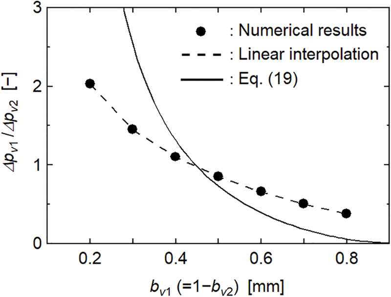
Figure 8: Comparison between Eq. (19) and numerical results
3.3 Effect of Cooled-Section Area
Numerical analyses were moreover conducted when the width of the heat pipe was increased with the cooled section. Fig. 9 shows the cross-section of the wider heat pipe. Like recently proposed striped wick structures [31,32], one wick structure with width bl was added to the vapor channel region. An additional vapor channel sub-region was termed Ch. 3 and the width was represented by bv3. Except for the increase in the width of the heat pipe and the addition of the wick structure, the wider heat pipe model was essentially the same as in Fig. 2. The governing equations of Eqs. (3)–(9) were applied to the three regions of the wider model. The boundary conditions of Eqs. (10)–(15) were used at corresponding boundaries. Since the wider model had two wick structures, Eqs. (14) and (15) were applied to four vapor-wick interfaces of the wick structures. The width of the cooled section was equal to the width (bt) of the heat pipe model, but the width of the heated section (bh) was smaller than bt. Instead of Eq. (1), bt is expressed by

Figure 9: Cross-section of the wider heat pipe with separated wick structures
Figs. 10a and 10b show the velocity and pressure distributions, respectively, on the x-y cross-section at z = 0.4 mm in the vapor channel region of the wider heat pipe. In addition, Fig. 10c shows the temperature distribution of the wider heat pipe. The numerical results were obtained with bv3 = 0.5 mm; the other numerical conditions were the same as those in Figs. 3b and 4b. In this calculation, because the width was increased, 81 (x-direction) × 56 (y-direction) × 54 (z-direction) mesh was generated in the calculation domain. Since the width of the heated section (bh) was 1.7 mm, the heated section was not located under Ch. 3. However, the velocity vector and pressure contour in Ch. 3 were similar to those in Ch. 2 because of the conductive heat transfer through the bottom container wall region. Although the thickness of the container wall (δw) was 0.2 mm, the heat conduction occurred effectively in the x-direction, which ensured the evaporation and condensation in Ch. 3. By using the average temperature at the adiabatic section (Ta,ave), the temperature differences within the heat pipe on the heated-section side (ΔTh) and cooled-section side (ΔTc) were evaluated respectively by


Figure 10: Fluid flow and heat transfer characteristics of the wider heat pipe
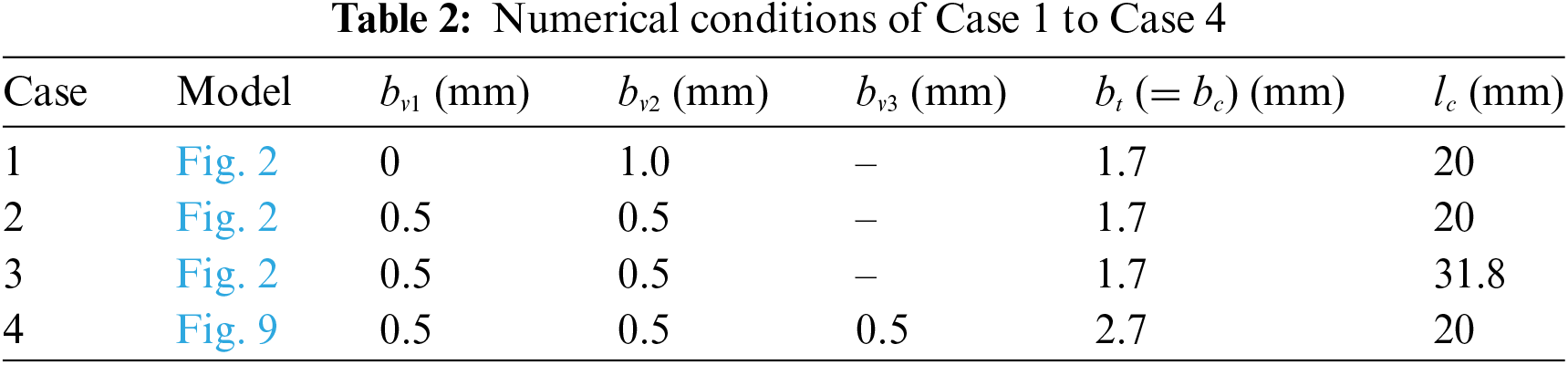
Fig. 11 shows ΔTh and ΔTc under four cases shown in Table 2. Note that ΔTh + ΔTc is ΔTt. Case 1 and Case 2 were the numerical conditions for the centered and separated wick structures, respectively, which were used in Section 3.1. Case 3 was the conditions when the cooled-section length (lc) was increased from Case 2. Case 4 was the same conditions as those in Fig. 10. Compared with Case 2, the cooled section became longer in Case 3 while became wider in Case 4, but the cooled-section areas in Case 3 and Case 4 were the same. ΔTh and ΔTc in Case 3 and Case 4 were smaller than those in Case 2, which confirmed the effectiveness of increasing the cooled-section area. Moreover, although the cooled-section areas were the same, the decreases in ΔTh and ΔTt from Case 2 to Case 4 were larger than those from Case 2 to Case 3. This is because of an increase in the vapor-wick interface area; the area in Case 4 was double the area in Case 3. Therefore, it is more effective to make the cooled-section width wider with additional wick structures than to make it longer. The ΔTt value in Case 4 was 44% of that in Case 1.

Figure 11: Temperature differences within the heat pipe for four cases
3.4 Comparison with Experimental Results
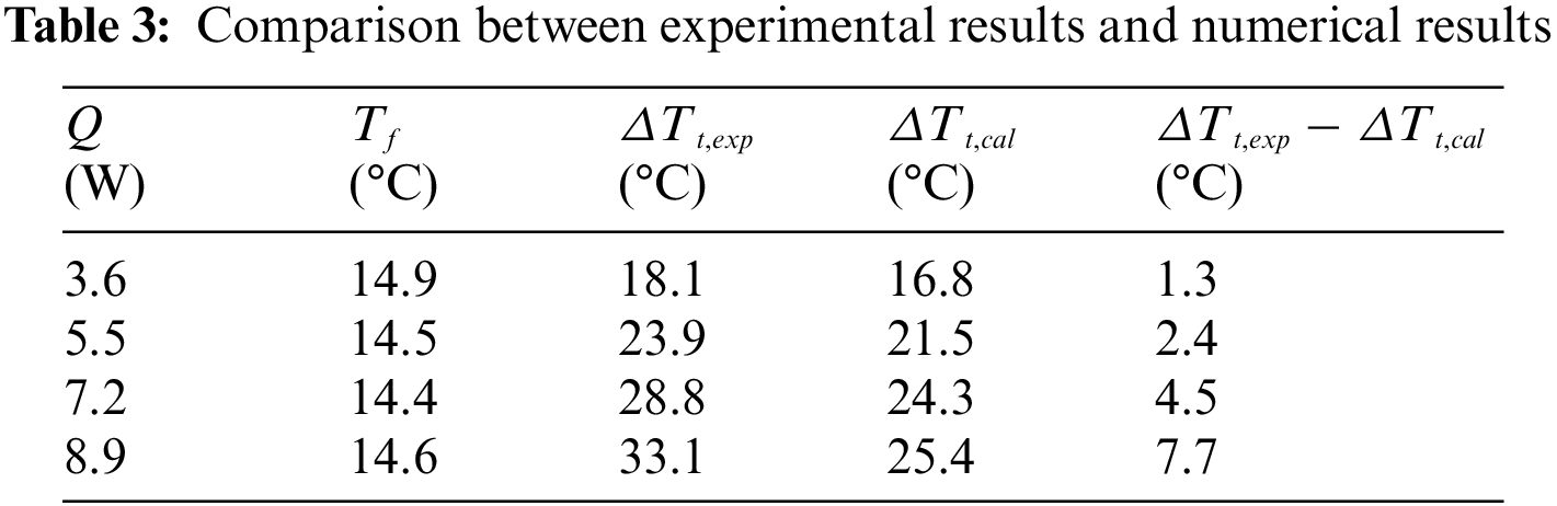
An extended experiment was conducted to compare numerical results with experimental results when wick structures were placed separately. The same experimental method as in the previous paper [18] was used except for the number of wick structures, wick width, and vapor-channel width. As shown in Fig. 12, two wick structures both with a width of 2.5 mm were placed in a semi-transparent heat pipe. The wick structures were made by sintering copper powders, and water was used as the working fluid. In experiments, the temperature difference (ΔTt,exp) between the heated and cooled sections was obtained at steady state by changing the heat input (Q) while keeping the cooling fluid temperature (Tf) constant. According to the experimental conditions, numerical results were also obtained, and the temperature difference (ΔTt,cal) between the heated and cooled sections was calculated from Eq. (16). Table 3 shows the comparison between ΔTt,exp and ΔTt, cal. Fairly good agreements were obtained when Q was between 3.6 and 7.2 W, which confirmed the validity of the present numerical analyses. However, the difference (ΔTt,exp − ΔTt, cal) was found to increase with increasing Q. This may be because of the occurrence of partial dryout in the wick structures due to the concentration of heat flux. Thus, to ensure the effectiveness of wick separation, it is important to supply sufficient liquid to areas where the concentration of heat flux occurs. Further experiments are needed for the concentration of heat flux.

Figure 12: Cross-section of a semi-transparent het pipe
Numerical analyses were conducted to discuss the effectiveness of wick separation in an ultra-thin heat pipe. The numerical results were compared with the case of a centered wick structure, and the effect of separated wick position on the effectiveness was investigated. Numerical analyses were also conducted when the heat-pipe width was increased with the cooled section. Furthermore, a comparison was made between experimental results and numerical results. The findings can be summarized as follows:
• The temperature difference of the heat pipe and the concentration of heat flux within the wick structure were reduced by separating the wick structure, which confirmed the effectiveness of the separation.
• The effectiveness of the separation was affected by the position of the separated wick structure. A simple equation was presented to determine the optimum position of the separated wick structures.
• The increase in the cooled-section width of the heat pipe with the addition of wick structures was more effective than the increase in the cooled-section length. The temperature difference of the heat pipe was reduced by 44% under the present numerical conditions.
• The comparison with experimental results confirmed the validity of the present numerical analyses. However, to ensure the effectiveness of wick separation, sufficient liquid supply is important to reduce the concentration of heat flux.
Acknowledgement: The authors would like to thank Mr. Junichi Akiyama, Mr. Daichi Kawamura, and Mr. Hiroto Ueno for useful discussions.
Funding Statement: The authors received no specific funding for this study.
Author Contributions: The authors confirm contribution to the paper as follows: study conception and design: Y. Koito; data collection: Y. Koito, A. Fukushima; analysis and interpretation of results: Y. Koito, A. Fukushima; draft manuscript preparation: Y. Koito. All authors reviewed the results and approved the final version of the manuscript.
Availability of Data and Materials: The data are available from the corresponding author upon reasonable request.
Conflicts of Interest: The authors declare that they have no conflicts of interest to report regarding the present study.
References
1. Ahamed, M. S., Saito, Y., Mashiko, K., Mochizuki, M. (2017). Characterization of a high performance ultra-thin heat pipe cooling module for mobile hand held electronic devices. Heat and Mass Transfer, 53, 3241–3247. https://doi.org/10.1007/s00231-017-2022-7 [Google Scholar] [CrossRef]
2. Kang, S., Choi, H., Park, S., Park, C., Lee, J. et al. (2019). Fire in your hands: Uderstanding thermal behavior of smartphones. MobiCom’19: Proceedings of the 25th Annual International Conference on Mobile Computing and Networking, no. 13, pp. 1–16. Los Cabos, Mexico. [Google Scholar]
3. Kim, K. M., Jeong, Y. S., Bang, I. C. (2019). Thermal analysis of lithium ion battery-equipped smartphone explosions. Engineering Science and Technology, an International Journal, 22(2), 610–617. https://doi.org/10.1016/j.jestch.2018.12.008 [Google Scholar] [CrossRef]
4. Zhou, W., Li, Y., Chen, Z., Yan, Y., Chen, H. (2021). Design and experimental study on a new heat dissipation method for watch-phones. In: Wen, C., Yan, Y. (eds.Advances in heat transfer and thermal engineering. Singapore: Springer. https://doi.org/10.1007/978-981-33-4765-6_107 [Google Scholar] [CrossRef]
5. Ju, Y. S. (2022). Thermal management and control of wearable devices. iScience, 25(7), 104587. https://doi.org/10.1016/j.isci.2022.104587 [Google Scholar] [PubMed] [CrossRef]
6. Han, A. Q. (2023). Thermal management and safety regulation of smart watches. Electronics Cooling. https://www.electronics-cooling.com/2023/08/thermal-management-and-safety-regulation-of-smart-watches/ (accessed on 16/01/2024). [Google Scholar]
7. Zhou, G., Li, J., Jia, Z. (2019). Power-saving exploration for high-end ultra-slim laptop computers with miniature loop heat pipe cooling module. Applied Energy, 239, 859–875. https://doi.org/10.1016/j.apenergy.2019.01.258 [Google Scholar] [CrossRef]
8. Li, Y., He, J., He, H., Yan, Y., Zeng, Z. et al. (2015). Investigation of ultra-thin flattened heat pipes with sintered wick structure. Applied Thermal Engineering, 86, 106–118. https://doi.org/10.1016/j.applthermaleng.2015.04.027 [Google Scholar] [CrossRef]
9. Tang, Y., Hong, S., Wang, S., Deng, D. (2019). Experimental study on thermal performances of ultra-thin flattened heat pipes. International Journal of Heat and Mass Transfer, 134, 884–894. https://doi.org/10.1016/j.ijheatmasstransfer.2018.12.178 [Google Scholar] [CrossRef]
10. Wong, S. C., Li, Y. C., Sung, C. Y., Huang, L. Q., Fu, C. Y. et al. (2024). Effects of vapor duct thickness on the thermal performance of ultra-thin vapor chambers under forced-convection cooling. Thermal Science and Engineering Progress, 47, 102285. https://doi.org/10.1016/j.tsep.2023.102285 [Google Scholar] [CrossRef]
11. Yan, W., He, X., Wang, S. (2024). Thermal performance of ultra-thin vapor chamber with etched micro-structure for electronics cooling. International Journal of Heat and Mass Transfer, 222, 125150. https://doi.org/10.1016/j.ijheatmasstransfer.2023.125150 [Google Scholar] [CrossRef]
12. Song, W., Xu, Y., Xue, L., Li, H., Guo, C. (2021). Visualization experimental study on silicon-based ultra-thin loop heat pipe using deionized water as working fluid. Micromachines, 12(9), 1080. https://doi.org/10.3390/mi12091080 [Google Scholar] [PubMed] [CrossRef]
13. Chen, A., Jiang, F., Dong, J., Chen, J., Zhu, Y. (2022). Design, fabrication and thermal performance of a novel ultra-thin loop heat pipe with printed wick structure for mobile electronics cooling. Applied Thermal Engineering, 200, 117683. https://doi.org/10.1016/j.applthermaleng.2021.117683 [Google Scholar] [CrossRef]
14. Zhou, W., Li, Y., Chen, Z., Deng, L., Gan, Y. (2019). A novel ultra-thin flattened heat pipe with biporous spiral woven mesh wick for cooling electronic devices. Energy Conversion and Management, 180, 769–783. https://doi.org/10.1016/j.enconman.2018.11.031 [Google Scholar] [CrossRef]
15. Chen, Z., Li, Y., Yu, J., Deng, L., Chen, H. et al. (2022). Fabrication and characterization of ultra-thin vapour chambers with printed copper powder wick. Applied Thermal Engineering, 201, 117734. https://doi.org/10.1016/j.applthermaleng.2021.117734 [Google Scholar] [CrossRef]
16. Tang, H., Xie, Y., Tang, Y., Wu, X., Wu, C. et al. (2022). Stress analysis and thermal performance of ultra-thin heat pipes for compact electronics. International Communications in Heat and Mass Transfer, 139, 106484. https://doi.org/10.1016/j.icheatmasstransfer.2022.106484 [Google Scholar] [CrossRef]
17. Koito, Y. (2019). Numerical analyses on heat transfer characteristics of ultra-thin heat pipes: Fundamental studies with a three-dimensional thermal-fluid model. Applied Thermal Engineering, 148, 430–437. https://doi.org/10.1016/j.applthermaleng.2018.10.119 [Google Scholar] [CrossRef]
18. Koito, Y., Chen, C. (2024). Thermal and hydrodynamic characteristics of an ultra-thin flattened centered-wick heat pipe: Experiments and numerical analyses. Applied Thermal Engineering, 239, 122064. https://doi.org/10.1016/j.applthermaleng.2023.122064 [Google Scholar] [CrossRef]
19. Yi, F., Gan, Y., Xin, Z., Li, Y., Chen, H. (2023). Analysis of thermal characteristics of the heat pipes with segmented composite wicks. International Journal of Thermal Sciences, 191, 108341. https://doi.org/10.1016/j.ijthermalsci.2023.108341 [Google Scholar] [CrossRef]
20. Yi, F., Gan, Y., Xin, Z., Li, Y., Chen, H. (2023). Experimental study on thermal performance of ultra-thin heat pipe with a novel composite wick structure. International Journal of Thermal Sciences, 193, 108539. https://doi.org/10.1016/j.ijthermalsci.2023.108539 [Google Scholar] [CrossRef]
21. Sheng, Y., Chen, Y., Yu, B., Tian, M., Jian, Q. et al. (2023). Influence of the liquid plug on the heat transfer performance of the ultra-thin flat heat pipe. Applied Thermal Engineering, 229, 120599. https://doi.org/10.1016/j.applthermaleng.2023.120599 [Google Scholar] [CrossRef]
22. Chen, Z., Li, Y., Zhang, R., Xin, Z., Yu, J. et al. (2023). Optimization of vapor-liquid channel parameters for ultrathin heat pipe with limited internal cavity. International Communications in Heat and Mass Transfer, 142, 106659. https://doi.org/10.1016/j.icheatmasstransfer.2023.106659 [Google Scholar] [CrossRef]
23. Shabgard, H., Faghri, A. (2011). Performance characteristics of cylindrical heat pipes with multiple heat sources. Applied Thermal Engineering, 31(16), 3410–3419. https://doi.org/10.1016/j.applthermaleng.2011.06.026 [Google Scholar] [CrossRef]
24. Grissa, K., Benselama, A. M., Lataoui, Z., Romestant, C., Bertin, Y. et al. (2017). Performance of a cylindrical wicked heat pipe used in solar collectors: Numerical approach with Lattice Boltzmann method. Energy Conversion and Management, 150, 623–636. https://doi.org/10.1016/j.enconman.2017.08.038 [Google Scholar] [CrossRef]
25. Agustina, D., Putra, N. (2023). Investigation of Micro CT based method for porosity estimation of sintered-wick heat pipes. Heliyon, 9(3), e13936. https://doi.org/10.1016/j.heliyon.2023.e13936 [Google Scholar] [PubMed] [CrossRef]
26. Ji, X., Xu, J., Abanda, A. M., Xue, Q. (2012). A vapor chamber using extended condenser concept for ultra-high heat flux and large heater area. International Journal of Heat and Mass Transfer, 55(17–18), 4908–4913. [Google Scholar]
27. Wu, S. C., Wang, D., Gao, J. H., Huang, Z. Y., Chen, Y. M. (2014). Effect of the number of grooves on a wick’s surface on the heat transfer performance of loop heat pipe. Applied Thermal Engineering, 71(1), 371–377. https://doi.org/10.1016/j.applthermaleng.2014.06.042 [Google Scholar] [CrossRef]
28. Ming, T., Li, Z., Zhao, S., Zhi, C., Liu, D. et al. (2024). Heat transfer enhancement of the ultra-thin flat heat pipe integrated with copper-fiber bundle wicks. Applied Thermal Engineering, 236, 21676. [Google Scholar]
29. Faghri, A., Buchko, M. (1991). Experimental and numerical analysis of low-temperature heat pipes with multiple heat sources. ASME Journal of Heat Transfer, 113(3), 728–734. https://doi.org/10.1115/1.2910624 [Google Scholar] [CrossRef]
30. Patankar, S. (1980). Numerical heat transfer and fluid flow, 1st edition. USA: CRC Press. [Google Scholar]
31. Cui, Z., Jia, L., Wang, Z., Dang, C., Yin, L. (2022). Thermal performance of an ultra-thin flat heat pipe with striped super-hydrophilic wick structure. Applied Thermal Engineering, 208, 118249. https://doi.org/10.1016/j.applthermaleng.2022.118249 [Google Scholar] [CrossRef]
32. Wang, M., Yang, Y., Sun, Y., Li, J., Hao, M. (2023). Experimental study on the thermal performance of ultra-thin flat heat pipes with novel multiscale striped composite wick structures. Heliyon, 9(10), e20840. https://doi.org/10.1016/j.heliyon.2023.e20840 [Google Scholar] [PubMed] [CrossRef]
Appendix. Derivation Process of Eq. (19)
The Hagen–Poiseuille equation is expressed as Eqs. (A-1) and (A-2) regarding the vapor pressure differences between the ends of Ch. 1 (Δpv1) and Ch. 2 (Δpv2), respectively.
where Q and d are the volume flow rate and hydraulic diameter, respectively. Since the symmetric condition was applied in Fig. 2, Ch. 1 actually had the vapor-wick interfaces on both sides (x = −bv1 and x = bv1) of the channel, while Ch. 2 had the interface on one side (x = bv1 + bl). When it was assumed that the evaporation/condensation rates at each vapor-wick interface were the same, the relation between Qv1 and Qv2 is simply given by
The width of Ch. 1 was actually 2bv1, and thus dv1 and dv2 are expressed respectively as
Eqs. (A-1) and (A-2) gave the ratio Δpv1/Δpv2 as
Eq. (19) was obtained by substituting Eqs. (A-3) to (A-5) into Eq. (A-6).
Cite This Article
 Copyright © 2024 The Author(s). Published by Tech Science Press.
This work is licensed under a Creative Commons Attribution 4.0 International License , which permits unrestricted use, distribution, and reproduction in any medium, provided the original work is properly cited.
 Downloads
 Citation Tools