
 Submit a Paper
 Propose a Special lssue
 Open Access
ARTICLE

Finite Element Analysis for Magneto-Convection Heat Transfer Performance in Vertical Wavy Surface Enclosure: Fin Size Impact
1 Department of Mathematics, American International University–Bangladesh, Kuratoli, Khilkhet, Dhaka, 1229, Bangladesh
2 Department of Physics, Faculty of Sciences, University of 20 Août 1955-Skikda, Skikda, 21000, Algeria
3 Department of Mathematics, Vijayanagara Sri Krishnadevaraya University, Vinayaka Nagar, Ballari, Karnataka, 583105, India
4 Department of Mathematics, Bangladesh University of Engineering and Technology (BUET), Dhaka, 1000, Bangladesh
5 Mechanical Engineering Department, College of Engineering and Islamic Architecture, Umm Al-Qura University, P.O. Box 5555, Makkah, Saudi Arabia
* Corresponding Author: F. Mebarek-Oudina. Email:
(This article belongs to the Special Issue: Advances in Computational Thermo-Fluids and Nanofluids)
Frontiers in Heat and Mass Transfer 2024, 22(3), 817-837. https://doi.org/10.32604/fhmt.2024.050814
Received 19 February 2024; Accepted 25 April 2024; Issue published 11 July 2024
 View Full Text
 Download PDF
Abstract
The goal of this paper is to represent a numerical study of magnetohydrodynamic mixed convection heat transfer in a lid-driven vertical wavy enclosure with a fin attached to the bottom wall. We use a finite element method based on Galerkin weighted residual (GWR) techniques to set up the appropriate governing equations for the present flow model. We have conducted a parametric investigation to examine the impact of Hartmann and Richardson numbers on the flow pattern and heat transmission features inside a wavy cavity. We graphically represent the numerical results, such as isotherms, streamlines, velocity profiles, local and mean Nusselt numbers, and average surface temperature. Comparisons between the results of this work and previously published work in a literature review have been produced to examine the reliability and consistency of the data. The different sizes of the fin surface significantly impact flow creation and temperature fields. Additionally, the long fin size is necessary to enhance the heat transfer rate on the right surface at large Richardson numbers and low Hartmann numbers. Fin surfaces can significantly increase the mixing of fluid inside the enclosure, which can mean reductions in reaction times and operating costs, along with increases in heat transfer and efficiency.Keywords
Nomenclature
| A | Amplitude |
| B0 | Magnetic field strength |
| B | Nondimensional fin thickness, |
| H | Nondimensional fin position |
| g | Gravitational force, m/s2 |
| Gr | Grashof number, W3gβ(Th − Tc)/v2 |
| Ha | Hartmann number, |
| L | Nondimensional fin length |
| N | Nondimensional distance normal to surface coordinates |
| Nuavg | Average Nusselt number |
| NuL | Local Nusselt number |
| Pr | Prandlt number, v/α |
| Re | Reynold number, ψW/v |
| Ri | Richardson number, Gr/Re2 |
| S | Nondimensional special coordinate along wavy surface |
| W | Enclosure height and width, m |
| ψ, φ | Nondimensional velocity in X and Y axis, respectively, (ψ = uW/α, φ = vW/α) |
| Greek Symbols | |
| α | Thermal diffusivity, m2/s |
| β | A coefficient of thermal expansion, 1/K |
| ρ | Local density, kg/m3 |
| μ | Dynamic viscosity, Ns/m2 |
| θ | Nondimensional temperature (T − Tc)/(Th − Tc) |
| υ | Kinematic viscosity, m2/s |
| λ | Number of oscillations |
| ε | Effectiveness |
| Subscripts | |
| avg | Average |
| c | Cool |
| h | Hot |
| f | Fin |
Researchers have become interested in convection heat transition in the driven enclosure due to its diverse range of applications, including solar thermal collectors, float glass manufacture, microelectronic devices, and electrical devices. A vast number of researchers have recognized the focus on lid-driven, various-shaped cavities, both from engineering and theoretical viewpoints. The present model’s specific engineering applications may include computer CPU heat sinks, radiators in cars, heat exchangers in power plants, heat transmission devices, and so on. Das et al. [1] examined free convection flow within the wavy frame enclosure. Their findings showed that a wavy surface’s amplitude and undulation numbers affect the components that control heat in an enclosure. The natural convection within a vertically wavy wall enclosing an unstable case was statistically modeled by Rostami [2]. Azizul et al. [3] reported the impact of a heat line concept on mixed convection indoors with a wavy surface frame and nanofluids. Free convection via a skewed design wavy porous chamber was examined by Misirlioglu et al. [4]. The impact of wavy base cover on combined convection heat augmentation in a driven chamber was documented by Al-Amiri et al. [5]. They assessed the effect of flow creation and heat removal characteristics on the number of wavy surfaces, the Richardson number, and the appropriateness of a wavy surface. Mushate [6] examined a porous enclosure with undulations using CFD to predict natural convection. The outcomes showed that the heat change rate improves as the Rayleigh number rises and decreases as the amplitude rises. Mansour et al. [7] used a heated non equilibrium model to explore a free convective porous cavity with a wavy form and the effect of thermic radiation. The coupled convection throw nanofluid flow within a wavy form cage was studied by Nada et al. [8]. They discovered that, with regard to geometry, base surface ratios, and the Richardson number, the heat replacement rate increases with an increase in the nanoparticle volume fraction. Using a nanofluid and Buongiorno’s mathematical description, Sheremet et al. [9] scrutinized free convection within a curved porous cavity with sinusoidal heat delivery on both level surfaces. Free convective movement in a non-uniformly heated curvy edge porous enclosure with nanofluid reporting the impacts of thermophoresis and Brownian dispersion was explored by Sheremet et al. [10]. Natural convection inside porous wavy structures, having sinusoidal warming and interior heat generation, was studied by Cheong et al. [11]. Alsabery et al. [12] examined the entropy-generating capabilities of a solid rotating cylinder with heat fluctuation in a warmed porous cavity underneath a curved framework. A recent heat conveyor study on convection inside a triangular wavy structure enclosure was made by Asad et al. [13].
Many engineering applications, including vacuum cleaners, washing machines, and blenders, all feature electric components that operate using magnetic principles. Ashorynejad et al. [14] explored combined nanofluid in a MHD convective wavy frame open enclosure. They followed the rule that the Nusselt number declines with an increase in a Hartmann number, but increases with a rise in Rayleigh number and nanoparticle size. Rahman et al. [15] studied the collective impacts of joule heating on magnetohydrodynamic convection within a driven frame enclosure. These authors and those of the references [16–19] emphasized that the Hartmann number significantly influences the thermal fluctuations of the flow. Additionally, Joule heating factors influence flow design and isotherms. Öztop et al. [20] provided a summary of coupled magneto-convection in a lid-driven, differentially heated, wavy-walled structure occupied with nanofluid. They showed that the rate of heat removal declines as the Hartmann number increases. Additionally, depending on Hartmann (Ha) and Richardson values, the nanoparticles might cause the heat substitution rate to climb or fall. There are more recent studies on square, wavy, and triangle cavities under the effect of a hydromagnetic field in [21–24].
A fin like computer CPU heat sinks, a radiator in a car, heat exchangers in power plants, and heat shifting devices are only a few examples of engineering applications that also incorporate flow construction and heat substitution inside the enclosure. In addition, cutting-edge technologies like fennec canines and hydrogen fuel cells work by discharging heat. Nag et al. [25] reviewed free convective flow in a differential thermal enclosure amidst a horizontal block on a hot wall. Tasnim et al. [26] investigated how free convection heat changed when a baffle was joined to a heated wall. They discovered that fin length and Rayleigh number have a massive effect on the influence of fin position on the rate of heat removal. Sun et al. [27] reported of mix-convection applying triangular conductive fins in a driven chamber. A triangular fin was recommended as a useful parameter for flow design and heat transport speed. The effect of baffles and their length on free convection within transition enclosures was examined by Xu et al. [28]. They determined that at a critical (Ra) level sensitive to fin length, the stream pattern near the fin surface changes from a steady to intermittently unstable flow. By affixing a vertical fin to the lower wall of the standard cage by Asad et al. [29]. Laminar natural convection was generated by Elatar et al. [30] in a square chamber with a special horizontal fin enclosed at various positions and heights connected to a heated surface. They investigated how flow design and heat removal components were affected by the length and position of the fins. Siddiqui et al. [31] studied combined convection in a micro-polar liquid sliding wall cavity. In open enclosures, the effects of parallel insulated baffles were examined by Palaniappan et al. [32]. According to the literature, further activities related to this study are [33–35]. Asad et al. [36] investigated the analytical modeling of the MHD boundary layer circulation of a chemically reacting upper convective Maxwell fluid via a vertical surface exposed to many stratifications with different characteristics. The performance of free convection and heat transfer in a curve-shaped enclosure was scrutinized by Asad et al. [37].
To the best of the researcher’s knowledge, this indicates that no question about the enclosure with a vertical fin and a wavy form on both sides has been examined. This surviving study will numerically scrutinize the influence of fin size on magneto-combined convective heat transition in a moving-wall, wavy-shaped wall enclosure attached to a vertical fin.
2 Problem Specifications with Mathematical Model
For the current investigation, a physical wavy model with boundary conditions estimates a wavy frame enclosure, as shown in Fig. 1. The thermo-physical characteristics of a fluid are maintained constant, with the exception of density variations in a buoyancy expression, which are controlled using the Boussinesq approximation. The dominance of viscous diffusion and radiation are also disregarded at the same time. The Newtonian, incompressible, steady, and laminar flow is generally assumed to represent the enclosing liquid.

Figure 1: Model with boundary conditions is schematically demonstrated
In accordance with the presumptions, the relevant governing equations (see reference [17]) are as follows:
The topical variables of the Eqs. (1)–(4) described above are, Pr, Ha, Gr, Re, and Ri, each of which is represented as
where H = (h/W) is a dimensionless fin location, L = (l/W) is a dimensionless fin size and B = (b/W) is a dimensionless fin thickness.
2.2 Calculation of Nusselt Number
The Nusselt number and global Nusselt number are induced as follows by incorporating the dimensionless parameters in Eq. (5):
3 Numerical Technique with Validation
The pertinent governing Eqs. (1)–(4) jointly amidst Eqs. (6a)–(6e) are constructed computationally using a Galerkin finite element approach. First, using the γ (penalty variable) and the incompressibility review of Eq. (1) as follows:
The following conservations of momentum Eqs. (2), (3) using Eq. (8), we get
Secondly, the progression of momentum and energy in Eqs. (9), (10) and (4) sequentially utilizing Eqs. (6a)–(6e) are organized by selecting the Galerkin finite element policy [38–40].
The engagement function estimates flow (ψ, φ), and heat qualities (θ) using a main set:
A Galerkin weighted residual approach and finite element techniques are employed within the inner node domain (Ω), integrating them across the computational domain to derive the nonlinear Eqs. (9), (10), and (4), which are then discretized using small free triangular meshes as illustrated in Fig. 2.

Figure 2: Distribution of the grid size of (a) 1702 and (b) 13273 elements
where the iteration, residual, and node numbers k, j, and i are listed consecutively. The procedures that came after Eqs. (12)–(14) were carried out using the Gaussian quadrature technique.
Lastly, Newton Raphson’s iteration scheme was engaged to find out residual equations iteratively. The elaborate clarification may be exposed in a literature review [13,37]. After a convergence inquiry, the computational approach’s convergence policies are realized and regarded as
where n is an N-R iteration loop and
Considering the current investigation at Pr = 0.71, L = 0.45, Ri = 1, λ = 2, and H = 0.50, identify the appropriate grid size. Table 1 displays the average Nusselt number of a fin, while Fig. 3 illustrates it. We examined a grid sensitivity assessment with various types of meshes and found an appropriate answer for the current research. Table 1 and Fig. 3 show that the grid size of 6844 nodes and 13,273 elements provided a satisfactory solution for the present numerical investigation.
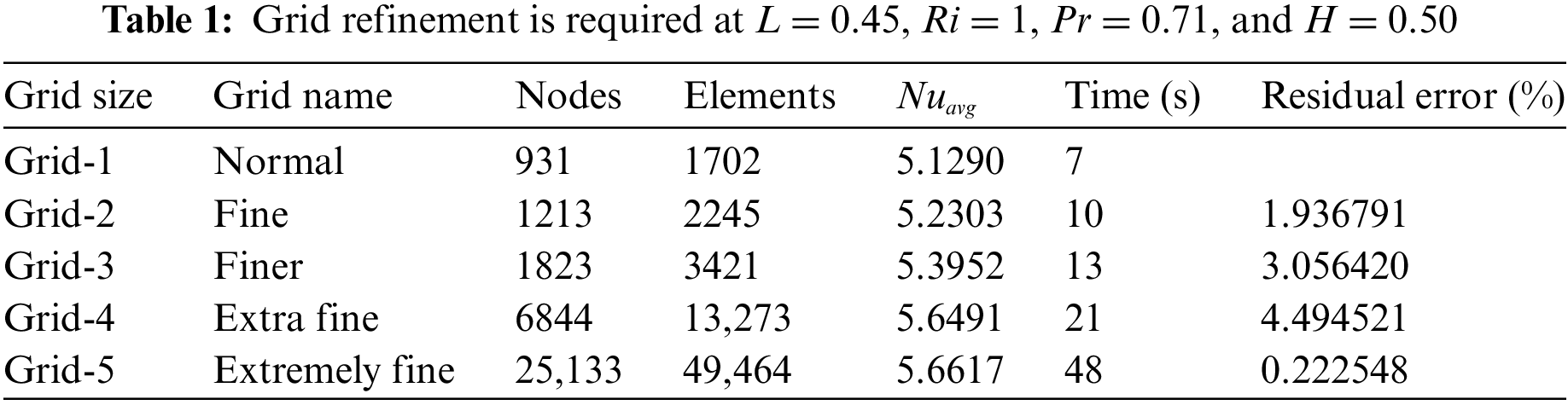

Figure 3: Grid survey for several elements
The mean Nusselt number on the right surface was compared between Elatar et al. [30] and Nag et al. [25] values at Ra = 106 and L = 0.20 to confirm the accuracy of the current model’s analytical results. With the largest derivation of less than 3.0%, the mean Nusselt number examined in Table 2 demonstrates the outstanding acceptance of those queries. Besides, a matching of local Nusselt numbers adjusted for the instant results with Elatar et al. [30] variant Ra (103, 104, 105, and 106) and H (0.25, 0.50, and 0.75) at L = 0.5 and B = 0.01 as exhibited in Fig. 4. The local Nusselt number can highlight the significant adjustment of instant results by Elatar et al. [30], as viewed in Fig. 4.

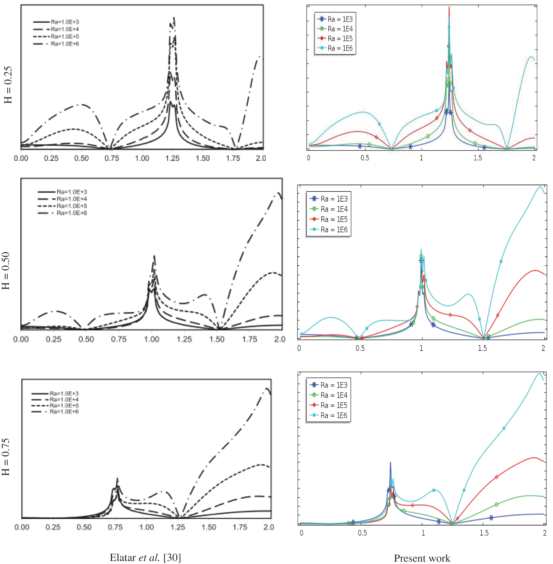
Figure 4: Comparison of NuL variant H and Ra at L = 0.5 and B = 0.01
In this research, our laptop configuration was Intel (R), Core (TM) i5-8350U, CPU @ (1.70–1.90) GHz, 8.00 GB (RAM), 64-bit operating system, x64-based processor.
The present numerical outcomes have been executed by employing the weighted residual tactics finite element scheme for exploring combined magneto-convection temperature substitution and flow field into a two-sided wavy surface enclosure to dominate the uniform magnetic field. The numerical findings of variant parameters like Richardson number (Ri), fin size (L), and Hartmann number are performed to determine the properties of flow patterns and temperature transport using streamlines, isotherms, and the average Nusselt number. The mean fluid temperature removal effectiveness inside the enclosure for three variant fin sizes of thermal cases is presented in graphical and tabulator form.
The results are visualized as streamlines in Fig. 5; isotherms in Fig. 6; and velocity outlines in Fig. 7 are scrutinized, acquiring the following ranges: are Hartmann number (Ha = 0, 20, 40, 60), fin size (L = 0.25, 0.35, 0.45), fin location (H = 0.50) with number of amplitude (A = 0.10), oscillations (λ = 2.0), and thickness of fin (B = 0.04) at Ri = 1.0. The buoyancy force within the cavity is stronger when Ha = 0, as can be seen in Fig. 5. Two vortices also develop inside the cavity, one of which is a main vortex caused by moving the top wall, and the other is a minor vortex generated by the right half of an enclosure. Again, the buoyancy force inside the cavity is strong for Ha = 20 and 40, and two vortices can be seen there. Another vortex occurred inside the hollow created by the movement of the moving wall at Ha = 60. Additionally, raising the fin surfaces also raises the flow patterns. The underlying physical reality is that, when the Hartmann number rises, the flow circulation diminishes. This is since using a magnetic field tends to slow down internal fluid dynamics. This indicates that a magnetic field impact has a massive impact on the flow field.

Figure 5: Streamlines for several Ha and L at A = 0.10, λ = 2.0 and Ri = 1.0

Figure 6: Isotherms for several Ha and L at A = 0.10, λ = 2.0 and Ri = 1
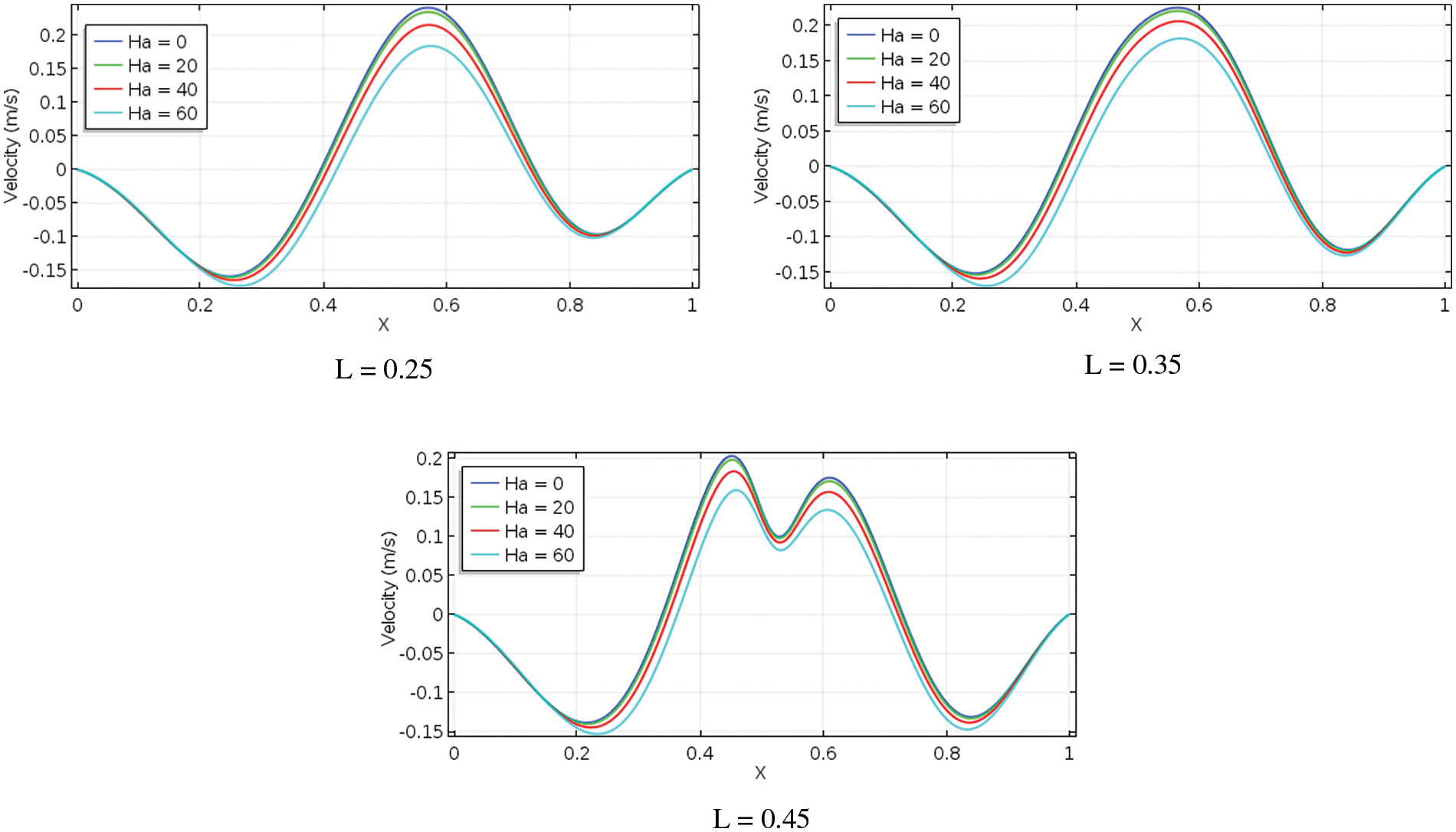
Figure 7: Velocity sketches for different L and Ha at A = 0.10, λ = 2.0 and Ri = 1.0
On the other hand, due to the larger values of Hartmann number, conduction-dominant heat transmission is seen from isotherms that are nearly identical and evenly dispersed in Fig. 6, which is consistent with the influence of the magnetic field. Fig. 7 shows the impact of the vertical component of the velocity contours at the enclosure variant’s horizontal midline at Ha, L, and Ri = 1. It is evident that the varying rate of velocity is distinct for each fin surface but comparable for each Hartmann number. Furthermore, as the Hartmann number decreases, the absolute value of the supreme and infimum velocities improves, raising the buoyancy force.
4.2 Impact of Richardson Number
The results are displayed as streamlines in Fig. 8; isotherms in Fig. 9; and velocity sketches in Fig. 10. The subsequent range, as Richardson number, fin size (L = 0.25, 0.35, 0.45), fin location (H = 0.50), number of amplitude (A = 0.1) with oscillations number (λ = 2.0), and fin thickness (B = 0.04) at Ha = 20 were taken into consideration for flow inside a vertical, wavy frame cavity, and then visually graphically. Fig. 8 shows that one vortex occurs within the lid wall-created enclosure when Ri = 0.1 and for all sizes of fins.

Figure 8: Streamlines for several L and Ri at A = 0.10, λ = 2.0 and Ha = 20


Figure 9: Isotherms for several L and Ri at A = 0.10, λ = 2.0 and Ha = 20

Figure 10: Velocity outlines for variant L and Ri at A = 0.10, λ = 2.0 and Ha = 20
This buoyancy force strength is high within a wavy cavity. Again, the flow configuration is comparable to Ri = 0.1 when Ri = 1.0 and for all sizes of fin, but two vortices emerge on the on the interior side of the wavy structure enclosure: a minor vortex and a major vortex. Furthermore, for all fin surfaces with extended Richardson numbers (Ri = 5 and 10), the buoyancy force has a stronger influence, and two vortices appear to be moving along the left and right of a wave-shaped hollow. The physical basis for this is that the buoyancy force’s impact on the flow area is more strongly influenced by the Richardson numbers and fin length. Fig. 9 shows that exposed isotherms show heat amplification caused mostly by conduction. It is clear that if heated and fin surfaces are present, a thick thermic frame layer is present, and that layer becomes thinner as Ri increases until it reaches 10 for all fin surfaces. Rising Ri and L enhance the curvature of isotherms, and heat lines are squeezed to the fin surface and vertical sides of wavy walls, which results in expanded heat replacement by convection. Fig. 10 illustrates the effects of velocity sketches on the horizontal center line for various fin sizes and Richardson’s number in relation to fin placement (H = 0.50), Ha = 20, and Pr = 0.71 of the cavity. Lower Ri and more subtle fluctuations in the velocity contours are the telltale signs of it. But the most dramatic difference is in the drawings with greater RI velocities. Furthermore, when Ri increases for all baffles, the absolute value of infima and dominance of a velocity increase.
Fig. 11 presents the mean fluid temperature (θavg) for several L, Ri, and Ha, whereas the value of the other parameter is kept constant. Fig. 11 shows that the mean liquid temperature rises steadily with an increase in the value of Ri when Ha is fixed. Additionally, it should be highlighted that when Ha reduces, the mean fluid temperature rises. Table 3 analyzes the statistical value of the mean fluid temperature inside the enclosure. Moreover, from Table 3, the highest mean fluid temperature inside the enclosure is 0.53403, found at L = 0.45, B = 0.50, Ha = 0, and Ri = 10.

Figure 11: θavg for different Ha, L and Ri at A = 0.10, λ = 2.0

A plot of the mean Nusselt number for several fin sizes (L), Hartmann numbers (Ha), and Richardson numbers (Ri) shows that, at the same time, the values of the other parameters are maintained at their default values, as observed in Fig. 12 and numerical values in Table 4. As exposed in Fig. 12, the mean Nusselt number rises firmly when the Hartmann number reduces for a unique fin length. Moreover, raising the Richardson number improved the mean Nusselt number on the right surface. Ri rises at a constant fin size; the buoyancy force expands and gains a heat replacement rate. Table 4 explores the statistical value of the mean Nusselt number through the right wall surface for several Ri, Ha, and L. As reported in Table 4, it proves that the value of heat removal performance rate is improved by inflating Ri and reducing Ha and L. Moreover, from Table 4, the supreme Nuavg is 7.6491 along the right cool surface exposed at L = 0.45, B = 0.50, and Ri = 10.

Figure 12: Nuavg for various L, Ri and Ha at A = 0.10 and λ = 2.0

4.4 Calculation of Fin Surface Effectiveness
Fin surface effectiveness is a variation that assesses an improvement in heat conversion within the cavity with fin surfaces compared to a case without fin surfaces, as pursued by Elatar et al. [30] as follows:
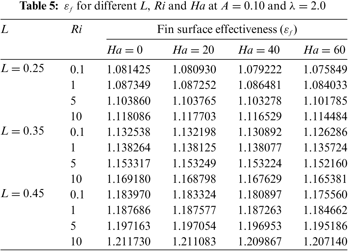
Fig. 13 exhibits fin effectiveness regarding distinct fin lengths
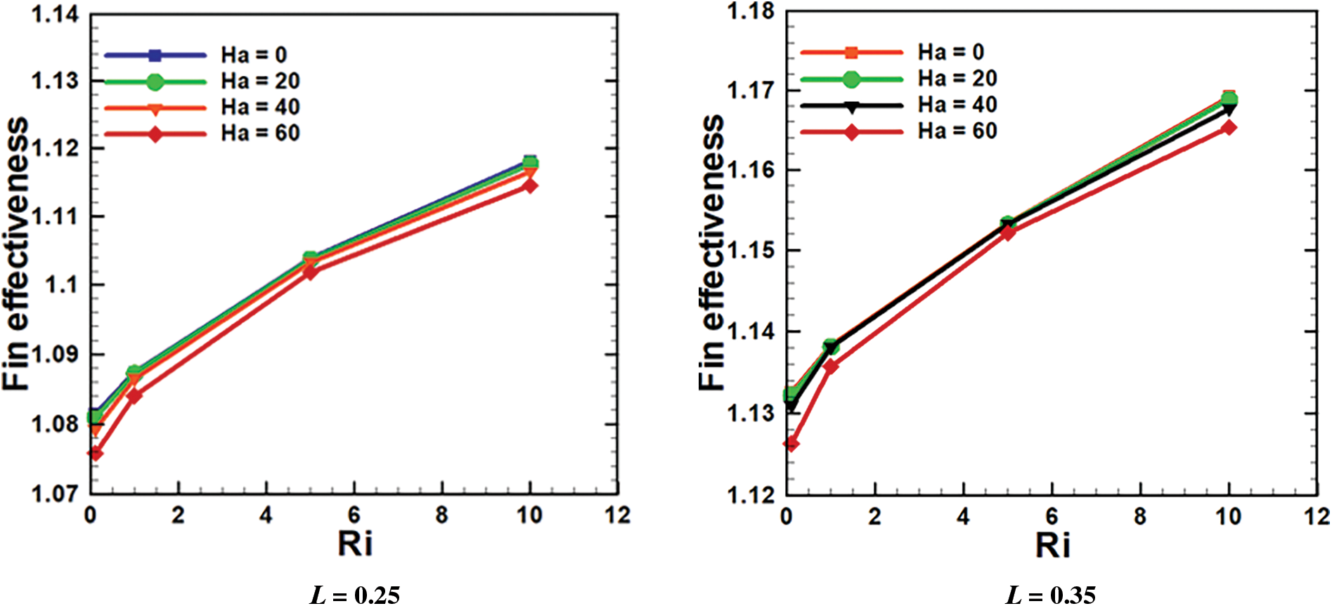

Figure 13: εf for various L, Ri and Ha at A = 0.10 and λ = 2.0
As a result, to increase the rate of heat release for individually fin length, a relatively high Richardson number is required. Table 5 shows the statistical value of fin effectiveness noted that the εf > 1 for all L. This means, based on the numerical data, the fin placement affects their efficacy for all fin surfaces. Moreover, from Table 5, the best fin effectiveness is 1.211730 audited at L = 0.45, H = 0.50, Ha = 0 and Ri = 10.
The overall destination of this inquiry is to determine the impact of fin size with Richardson number and Hartmann number variance on hydromagnetic mixed convective flow with heat removal performance within a two-side wavy surface enclosure. The numerical method was verified by contrasting the mean Nusselt number and local Nusselt number obtained by the code with previously published data for existing inquiries. Based on the results, the following will be stated:
• These outcomes confirmed that the fin length difference greatly influences the flow features and temperature field within the cavity.
• A higher Richardson number and a lower Hartman number can be achieved by keeping the fin size constant and improving the heat transfer performance rate. As the fin size is extended, the average fluid temperature as well as the heat production speed increase.
• The highest mean fluid temperature inside the cavity is 0.53403, or 11.45% (approx.), found at L = 0.45, B = 0.50, Ha = 0, and Ri = 10.
• When the Richardson number progresses to a uniform fin size, the buoyancy force increases, and the heat transfer rate improves. For a specific fin size, as the value of Ririses and Ha decreases, the mean Nusselt number rises. The supreme Nuavg is 7.6491, or 6.48% (approx.) along the right cool surface exposed at L = 0.45, B = 0.50, and Ri = 10.
• The baffle’s effectiveness is improved by raising Ri and reducing Ha for all changes in fin sizes while the fin is in a particular position. The maximum fin effectiveness is 1.211730, or 7.728% (approx.) audited at L = 0.45, H = 0.50, Ha = 0, and Ri = 10.
Acknowledgement: The authors express their gratitude to their affiliated universities and thank the Deanship of Scientific Research at Umm Al-Qura University for supporting this work through Grant Code: 22UQU4240002DSR19.
Funding Statement: The authors received no specific funding for this study.
Author Contributions: The authors confirm contribution to the paper as follows: study conception and design, data collection, analysis and interpretation of results, draft manuscript preparation: Md. Fayz-Al-Asad, F. Mebarek-Oudina, H. Vaidya, Md. Shamim Hasan, and Md. Manirul Alam Sarker, A. I. Ismail. All authors reviewed the results and approved the final version of the manuscript.
Availability of Data and Materials: Data are available on request.
Conflicts of Interest: The authors certify that there are no conflicts of interest about the publication of this research.
References
1. Das PK, Mahmud S. Numerical investigation of natural convection inside a wavy enclosure. Int J Therm Sci. 2003;42(4):397–406. doi:10.1016/S1290-0729(02)00040-6. [Google Scholar] [CrossRef]
2. Rostami J. Unsteady natural convection in an enclosure with vertical wavy walls. Heat Mass Trans. 2008;44:1079–87. doi:10.1007/s00231-007-0349-1. [Google Scholar] [CrossRef]
3. Azizul FM, Alsabery AI, Hashim I, Chamkha AJ. Impact of heat source on combined convection flow inside wavy-walled cavity filled with nanofluids via heatline concept. Appli Math Comp. 2021;393. doi:10.1016/j.amc.2020.125754. [Google Scholar] [CrossRef]
4. Misirlioglu A, Baytas AC, Pop I. Natural convection inside an inclined wavy enclosure filled with a porous medium. Trans Por Med. 2006;64:229–46. doi:10.1007/s11242-005-2857-0. [Google Scholar] [CrossRef]
5. Al-Amiri A, Khanafer K, Bull J, Pop I. Effect of sinusoidal wavy bottom surface on mixed convection heat transfer in a lid-driven cavity. Int J Heat Mass Trans. 2007;50(9–10):1771–80. [Google Scholar]
6. Mushate KS. CFD prediction of natural convection in a wavy cavity filled with porous medium. Global J Res Eng. 2011;11(2):29–45. [Google Scholar]
7. Mansour M, El-Aziz MA, Mohamed R, Ahmed SE. Numerical simulation of natural convection in wavy porous cavities under the influence of thermal radiation using a thermal non-equilibrium model. Trans Por Med. 2011;86:585–600. doi:10.1007/s11242-010-9641-5. [Google Scholar] [CrossRef]
8. Nada EA, Chamkha AJ. Mixed convection flow of a nanofluid in a lid-driven cavity with a wavy wall. Int Comm Heat Mass Trans. 2014;57:36–47. doi:10.1016/j.icheatmasstransfer.2014.07.013. [Google Scholar] [CrossRef]
9. Sheremet MA, Pop I. Natural convection in a wavy porous cavity with sinusoidal temperature distributions on both side walls filled with a nanofluid: Buongiorno’s mathematical model. J Heat Trans. 2015;137(7). [Google Scholar]
10. Sheremet M, Cimpean D, Pop I. Free convection in a partially heated wavy porous cavity filled with a nanofluid under the effects of Brownian diffusion and thermophoresis. Appli Therm Eng. 2017;113:413–8. doi:10.1016/j.applthermaleng.2016.11.033. [Google Scholar] [CrossRef]
11. Cheong HT, Sivasankaran S, Bhuvaneswari M. Natural convection in a wavy porous cavity with sinusoidal heating and internal heat generation. Int J Num Meth Heat Fluid Flow. 2017;27(2):287–309. doi:10.1108/HFF-07-2015-0272. [Google Scholar] [CrossRef]
12. Alsabery AI, Tayebi T, Chamkha AJ, Hashim I. Effect of rotating solid cylinder on entropy generation and convective heat transfer in a wavy porous cavity heated from below. Int Comm Heat Mass Trans. 2018;95:197–209. doi:10.1016/j.icheatmasstransfer.2018.05.003. [Google Scholar] [CrossRef]
13. Asad MFA, Alam MN, Tunç C, Sarker MMA. Heat transport exploration of free convection flow inside enclosure having vertical wavy walls. J Appli Comp Mech. 2021;7(2):520–7. [Google Scholar]
14. Ashorynejad HR, Shahriari A. MHD natural convection of hybrid nanofluid in an open wavy cavity. Res Phys. 2018;9:440–55. [Google Scholar]
15. Rahman MM, Alim MA, Sarker MMA. Numerical study on the conjugate effect of joule heating and magnato-hydrodynamics mixed convection in an obstructed lid-driven square cavity. Int Comm Heat Mass Trans. 2010;37:524–34. doi:10.1016/j.icheatmasstransfer.2009.12.012. [Google Scholar] [CrossRef]
16. Mebarek-Oudina F, Chabani I, Vaidya H, Ismail AI. Hybrid nanofluid magneto-convective flow and porous media contribution to entropy generation. Int J Num Meth Heat Fluid Flow. 2024;33(1):2540003. doi:10.1108/HFF-06-2023-0326. [Google Scholar] [CrossRef]
17. Ali MM, Alim MA, Ahmed SS. Magnetohydrodynamic mixed convection flow in a hexagonal enclosure. Procedia Eng. 2017;194:479–86. doi:10.1016/j.proeng.2017.08.174. [Google Scholar] [CrossRef]
18. Mebarek-Oudina F, Preeti Sabu, Vaidya AS, Lewis R.W. H, Areekara S, Mathew A, et al. Hydromagnetic flow of magnetite-water nano-fluid utilizing adapted Buongiorno model. Int J Mod Phys B. 2024;38(1): 2450003. doi:10.1142/S0217979224500036. [Google Scholar] [CrossRef]
19. Ramesh K, Mebarek-Oudina F, Ismail AI, Jaiswal BR, Warke AS, Lodhi RK, et al. Computational analysis on radiative non-Newtonian Carreau nanofluid flow in a microchannel under the magnetic properties. Sci Iran. 2023;30(2):376–90. [Google Scholar]
20. Öztop HF, Sakhrieh A, Abu-Nada E, Al-Salem K. Mixed convection of MHD flow in nanofluid filled and partially heated wavy walled lid-driven enclosure. Int Comm Heat Mass Trans. 2017;86:42–51. doi:10.1016/j.icheatmasstransfer.2017.05.011. [Google Scholar] [CrossRef]
21. Mansour MA, Rashad AM, Morsy Z. MHD free convection and sinusoidal heating in a wavy cavity filled with a heat generation porous medium using Cu-water nanofluids. Comp Therm Sci: Int J. 2020;12(3):217–32. doi:10.1615/ComputThermalScien.v12.i3. [Google Scholar] [CrossRef]
22. Cho C. Mixed convection heat transfer and entropy generation of Cu-water nanofluid in wavy-wall lid-driven cavity in presence of magnetic field. Int J Mech Sci. 2019;151:703–14. doi:10.1016/j.ijmecsci.2018.12.017. [Google Scholar] [CrossRef]
23. Mebarek-Oudina F, Fares R, Aissa A, Lewis RW, Abu-Hamdeh N. Entropy and convection effect on magnetized hybrid nano-liquid flow inside a trapezoidal cavity with zigzagged wall. Int Comm Heat Mass Trans. 2021;125:105279. doi:10.1016/j.icheatmasstransfer.2021.105279. [Google Scholar] [CrossRef]
24. Bouselsal M, Mebarek-Oudina F, Biswas N, Ismail AI. Heat transfer enhancement using Al2O3-MWCNT hybrid-nanofluid inside a tube/shell heat exchanger with different tube shapes. Micromachines. 2023;14:1072. doi:10.3390/mi14051072. [Google Scholar] [PubMed] [CrossRef]
25. Nag A, Sarkar A, Sastri VMK. Natural convection in a differentially heated square cavity with horizontal partition plate on the hot wall. Com Meth App Mech Eng. 1993;110(1–2):143–56. [Google Scholar]
26. Tasnim SH, Collins MR. Numerical analysis of heat transfer in a square cavity with a baffle on the hot wall. Int Comm Heat Mass Trans. 2004;31:639–50. doi:10.1016/S0735-1933(04)00051-X. [Google Scholar] [CrossRef]
27. Sun C, Yu B, Öztop HF, Wang Y, Wei J. Control of mixed convection in lid-driven enclosures using conductive triangular fins. Int J Heat Mass Trans. 2011;54(4):894–909. doi:10.1016/j.ijheatmasstransfer.2010.09.068. [Google Scholar] [CrossRef]
28. Xu F, Saha SC. Transition to an unsteady flow induced by a fin on the sidewall of a differentially heated air-filled square cavity and heat transfer. Int J Heat Mass Trans. 2014;71:236–44. doi:10.1016/j.ijheatmasstransfer.2013.12.019. [Google Scholar] [CrossRef]
29. Asad MFA, Sarker MMA, Munshi MJH. Numerical investigation of natural convection flow in a hexagonal enclosure having vertical fin. J Scie Res. 2019;11(2):173–83. doi:10.3329/jsr.v11i2.38797. [Google Scholar] [CrossRef]
30. Elatar A, Teamah MA, Hassab MA. Numerical study of laminar natural convection inside square enclosure with single horizontal fin. Int J Ther Sci. 2016;99:41–51. doi:10.1016/j.ijthermalsci.2015.08.003. [Google Scholar] [CrossRef]
31. Siddiqui MA, Riaz A, Khan I, Nisar KS. Augmentation of mixed convection heat transfer in a lid-assisted square enclosure utilizing micropolar fluid under magnetic environment: a numerical approach. Results Phys. 2020;18:103245. doi:10.1016/j.rinp.2020.103245. [Google Scholar] [CrossRef]
32. Palaniappan G, Murugan M, Mdalla QMA, Abdallaand B, Doh DH. Numerical investigation of open cavities with parallel insulated baffles. Int J Heat Tech. 2020;38(3):611–21. doi:10.18280/ijht. [Google Scholar] [CrossRef]
33. Shulepova EV, Sheremet MA, Öztop HF, Abu-Hamdeh N. Mixed convection of Al2O3-H2O nanoliquid in a square chamber with complicated fin. Int J Mech Sci. 2020;165:105192. doi:10.1016/j.ijmecsci.2019.105192. [Google Scholar] [CrossRef]
34. Ali A, Mebarek-Oudina F, Barman A, Das S, Ismail AI. Peristaltic transportation of hybrid nano-blood through a ciliated micro-vessel subject to heat source and Lorentz force. J Ther Anal Calor. 2023;148:7059–83. doi:10.1007/s10973-023-12217-x. [Google Scholar] [CrossRef]
35. Dharmaiah G, Mebarek-Oudina F, Balamurugan KS, Vedavathi N. Numerical analysis of the magnetic dipole effect on a radiative ferromagnetic liquid flowing over a porous stretched sheet. Fluid Dyn Mater Process. 2024;20(2):293–310. doi:10.32604/fdmp.2023.030325. [Google Scholar] [CrossRef]
36. Asad MFA, Oreyeni T, Yavuz M, Olanrewaju PO. Analytic simulation of MHD boundary layer flow of a chemically reacting upper-convected Maxwell fluid past a vertical surface subjected to double stratifications with variable properties. Europ Phy J Plus. 2022;137:813. doi:10.1140/epjp/s13360-022-03014-w. [Google Scholar] [CrossRef]
37. Asad MFA, Alam MN, Rashad AM, Sarker MMA. Impact of undulation on magneto-free convective heat transport in an enclosure having vertical wavy sides. Int Comm Heat Mass Trans. 2021;127:105579. doi:10.1016/j.icheatmasstransfer.2021.105579. [Google Scholar] [CrossRef]
38. Reddy JN. An introduction to the finite element method. New York: McGraw-Hill; 1993. [Google Scholar]
39. Dechaumphai P. Finite element method in engineering. 2nd ed. Bangkok: Chulalongkorn University Press; 1999. [Google Scholar]
40. Taylor C, Hood P. A numerical solution of the Navier-Stokes equations using finite element technique. Comp Fluids. 1973;1:73–89. doi:10.1016/0045-7930(73)90027-3. [Google Scholar] [CrossRef]
Cite This Article
 Copyright © 2024 The Author(s). Published by Tech Science Press.
This work is licensed under a Creative Commons Attribution 4.0 International License , which permits unrestricted use, distribution, and reproduction in any medium, provided the original work is properly cited.
 Downloads
 Citation Tools