
 Submit a Paper
 Propose a Special lssue
 Open Access
ARTICLE

Drive Train Cooling Options for Electric Vehicles
1 Fujikura Automotive Europe GmbH, Manchinger Strasse 114, Ingolstadt, D-85053, Germany
2 Fujikura Ltd., 1-5-1 Kiba, Koto-Ku, Tokyo, 135-8512, Japan
* Corresponding Author: Randeep Singh. Email:
Frontiers in Heat and Mass Transfer 2024, 22(3), 703-717. https://doi.org/10.32604/fhmt.2024.050744
Received 16 February 2024; Accepted 15 May 2024; Issue published 11 July 2024
 View Full Text
 Download PDF
Abstract
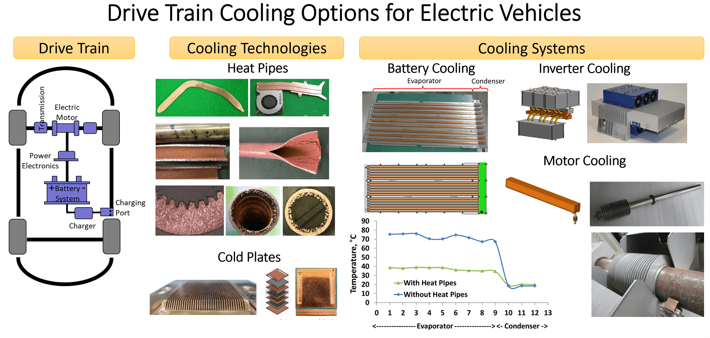
Electrification of vehicles intensifies their cooling demands due to the requirements of maintaining electronics/electrical systems below their maximum temperature threshold. In this paper, passive cooling approaches based on heat pipes have been considered for the thermal management of electric vehicle (EV) traction systems including battery, inverter, and motor. For the battery, a heat pipe base plate is used to provide high heat removal (180 W per module) and better thermal uniformity (<5°C) for the battery modules in a pack while downsizing the liquid cold plate system. In the case of Inverter, two phase cooling system based on heat pipes was designed to handle hot spots arising from high heat flux (~100 W/cm)–for liquid cooling and provide location independence and a dedicated cooling approach-for air cooling. For EV motors, heat pipe-based systems are explored for stator and rotor cooling. The paper also provides a glimpse of development on high-performance microchannel-based cold plate technologies based on parallel fins and multi-layer 3D stacked structures. Specifically, this work extends the concept of hybridization of two-phase technology based on heat pipes with single-phase technology, predominately based on liquid cooling, to extend performance, functionalities, and operational regime of cooling solutions for components of EV drive trains. In summary, heat pipes will help to improve and extend the overall reliability, performance, and safety of air and liquid cooling systems in electric vehicles.Graphic Abstract
Keywords
Nomenclature
| Rt | Thermal resistance, °C/W |
| T | Temperature, °C |
| Heat flow, W | |
| Subscripts | |
| h | Hot side |
| c | Cold side |
Electric vehicles consist of electric-based propulsion that comprises of battery pack, inverter assembly, and motor as the principal components to aid in traction of the vehicle. These vehicle powering systems are supported by secondary parts for power transfer (cables), power conversion (Inversion, conversion), and charging of battery (on-board or induction charger, port for charging). Fig. 1 presents a simplified form of a vehicle electric power train with a charging system from the inlet port to the battery, and a discharging system (or traction system) from the battery to the motor [1–5]. In Fig. 2, the heat output from different components of the traction system is presented, along with automotive electronics (e.g., display, headlamp, ECU) for comparison purposes. It can be seen that power systems cover a wide range of load-distance spectrum with the general trend towards high power and longer heat transfer distances. In other words, thermal solutions for electric vehicles will need to be developed to handle high flux and transfer high power over significant distances while satisfying robust structural quality. Such requirements are unique for two-phase and single-phase systems originally developed for consumer and high-performance stationary electronics. Thus, it is necessary to focus on the development of high-performance, modular, and dedicated thermal systems for electric vehicles.

Figure 1: Electric drive components in electric vehicle

Figure 2: Waste heat output from different electronic/electric system in car
Electric vehicles, in contrast to engine vehicles, have more specific and specialized cooling needs. Specific needs because of the high sensitivity of electronics and electrical systems to temperature. Engine vehicle generally uses materials, which have high tolerance to wider temperature ranges. Specialized needs because of exclusive requirements and design customization needed per system functionalities and specifications. For example, EVs typically require cooling solutions for high-voltage systems with isolation needs to prevent short-circuiting. New-generation optical systems in headlamps and displays have low-temperature requirements to maintain good optical performance from such devices. EVs are predominately built out of electronic/electric systems that are made of materials that are thermally sensitive to temperature for performance and structural integrity. Additionally, there is a general trend in automotive, including engine vehicles, towards higher electrification arising from autonomy and computerization of vehicular functions. Therefore, overall cooling requirements in automotive are on the rise.
As stated earlier, the overall electric propulsion system consists of an electric systems (like cables, connector, fuse, motor), an electronic systems (like inverter, converter, OBC), and an electrochemical systems (like Li-ion batteries). Each of these categories has very specific cooling requirements due to the different materials and functions of these systems. Additionally, each system even in similar categories has diverse thermal challenges owing to its electrical architecture (or simply design), location in the car (front, back, in-cabin, under-cabin), and cooling method (air-base, liquid-base, conduction to chassis). Cooling requirements of these devices could be dictated by material temperature limits (SiC chips have higher temperature limits than Si chips), the criticality of the system (autonomous drive system need higher redundancies than infotainment system), and sometimes mere system cost (high cooling performance to avoid replacement costs).
For simplicity, in this paper, we have chosen three major systems from electric drive trains to provide an overall overview of types of cooling requirements, thermal solutions development at component and overall device levels that are needed in the area of traction systems.
To provide maximum performance and keep long-term reliable operation, the majority of systems in electric drive lines need thermal control to manage their working temperatures. Here, the thermal needs of these different components are dissimilar owing to their material, built-up, architecture, and operational requirements. Typical electrical systems like electric motors and electronic systems based on semiconductors and integrated gate bipolar transistors (IGBTs) can endure elevated working temperatures in the range of 100 to 150°C. In contrast, electrochemical systems including batteries are temperature-sensitive and need to be kept at much lower working temperatures (40°C or below) [6]. Batteries with lithium-ion chemistry in different shape factors and builds including cylindrical, prismatic, or pouch cells provide an overall acceptable mix of energy density and cyclic charge-discharge efficiency.
Li-ion batteries, like the human body, have to be kept in the narrow temperature range of 25°C to 40°C for an extended lifetime and good working performance. The driving range of battery-operated vehicles is reduced in both hot summer (18% on +35°C, 40% RH conditions) and cold winter days (36% on −10°C, 90% RH) due to energy needs to manage battery temperature in permissible range as well as cabin conditioning. Battery thermal management is the most critical topic in electric vehicles and affects overall vehicle reliability, performance, and price levels.
Traction inverters, also commonly referred as power electronics, provide a controlling and switching link between battery and motor. Development in inverters has provided variable challenges for cooling systems to handle high heat fluxes (35–100 W/cm2), and large heat loads (1–2 kW) while keeping working temperatures within limits of semiconductor materials used in inverter built.
Motors have main heat sources such as bearings and electrical coils. Both components can sustain temperature levels 100–150°C range. The motor could be cooled at the stator or rotor area depending on motor type, design, and main areas of thermal generation. For rotor cooling, the main challenges come from the fact that the heat source is in rotational motion so a cooling system will be required to give thermal and structural performance while in high RPM motion.
Fig. 3 presents a thermal roadmap for electric vehicles that helps to identify applicable cooling technology w.r.t heat ranges. Considering the above discussion, it is important to understand that the existing state of cooling technology in vehicles has been mainly developed to manage engines and other mechanical systems, and therefore could not provide an efficient migration to vehicles with significant electric built (plug-in hybrids-PHEVs, battery electric vehicles-BEVs). Electronic/electric systems in EVs give out concentrated heat fluxes, which need to be managed by a highly developed cooling system (single-phase as well as two-phase). In Fig. 3, there is an opportunity to improve the operational regime for air cooling, two-phase solutions as well as liquid cooling within the capability index of the respective technology. Particularly, hybridization or optimum mixing of technologies would help to provide cooling design breakthroughs in the area of traction drive trains. Here, heat pipes mainly refer to capillary-driven passive heat transfer devices with co-existing vapor and liquid phases in counterflow. Devices like loop heat pipes (LHP), and pulsating heat pipes (PHP) do have specific application niches in automotive, however, these are not considered in this investigation to limit the scope.
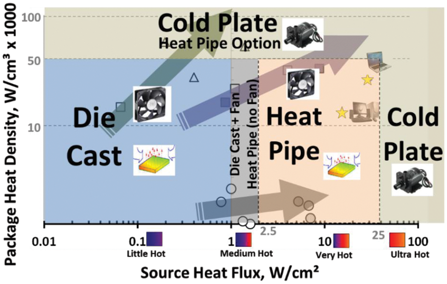
Figure 3: Thermal roadmap for automotive
In this paper, cooling challenges for components of EV drive trains have been outlined for the relevance of current work. Technological improvements in the area of two-phase and single-phase have been stated, followed by enhanced cooling systems built and characterization as outcomes of the present research undertaking.
As discussed in the previous section, different components in electric power train have different permissible temperatures (owing to material and reliability needs), structural (owing to component location, built), electrical (owing to voltage class–low, high), and operational (owing to functional modes–sudden surge, steady, transient) requirements.
The cooling device is designed to achieve the required thermal resistance, Rt, as determined by its source permissible temperature (Th) and output heat load (
Other requirements are more component-specific and targeted to achieve maximum performance and lifetime for the device while operating reliably and safely. The cooling device should be able to maintain temperature uniformity within ±5°C over an active heat source to reduce thermal stress on the semiconductor surface or Li-ion cell. For high-voltage devices, cooling devices need to maintain an isolation gap of 1–2 kV/mm (depending on voltage and proximity of other power sources). In traction inverters, cooling devices need to possess 2 to 3 times higher cooling capacity or thermal mass to overcome and absorb sudden power surges of waste heat during vehicle acceleration/deceleration. Similarly, charging line components and battery systems need to have adequate cooling means to keep the temperature within allowable ranges during normal/fast-charging cycles. In addition to these, thermal solutions are required to satisfy lifetime requirements regarding freeze sustainability, cyclic temperature operation, high-temperature endurance, and the like. Geometrical tolerances and structure of the device should remain intact during the designed lifetime.
In this section, cooling technologies of interest in the thermal management of traction systems of EVs have been identified with key developments that have been in effect to make these technologies more applicable in terms of performance, reliability, and cost. Fig. 4 presents length vs. capacity for different cooling technologies with solid conduction at lower bands, two-phase solution covering most of the low to medium band, and liquid phase towards long distances and high heat load bands.

Figure 4: Heat transfer performance of different cooling technologies
In EV thermal management, heat pipes have significant scope to apply as high conductive heat transfer devices in air as well as liquid cooled system. Heat pipes could complement cooling solution in the following different ways:
① Enhance temperature uniformity or reduce hot spots.
② Reduce liquid leakage hazard in the proximity of high voltage area (due to limited liquid in the heat pipe. No drip leak).
③ Improve thermal response of cooling solution for sudden power surges.
④ Increase the thermal capacity of the overall cooling system.
Typically, heat pipe constitutes of axial, fibre, or sinter power wick as shown in Fig. 5 [7–9]. In order to enhance the effective thermal conductivity of heat pipe and overall heat load, wick design could be enhanced in different ways. Fibre wick is beneficial to achieve smaller thicknesses for heat pipe while keeping high heat capacity whereas power wick helps to achieve high evaporative/condensation heat transfer coefficients along with high capillary pressure for heat transfer against gravity. Fig. 6 presents the heat transfer capacity of a diameter 9.4 mm heat pipe with 0.5 and 1 mm thick copper powder wick. As evident, the thermal capacity of the heat pipe could be almost doubled by choosing the appropriate size and thickness of the wick.

Figure 5: Types of heat pipe wick structure

Figure 6: Thermal performance of powder wick with different thicknesses
In Fig. 7, the heat transport capacity and thermal resistance of the 570 mm long heat pipe have been shown to improve by using a combination of fibre and powder wick. A maximum heat load of 50 W was achieved while thermal resistance was improved from 0.5 to 0.09°C/W. Such enhancements are possible due to the best mix of permeability (possible from linear flow passages in fibre wick), and capillary pressure/phase heat transfer coefficients (possible from fine pore size of powder wick). In this case, relative placement and geometrical design of two wick types are important to achieve the best mix of thermal capacity and thermal resistance (or thermal conductivity) of the heat pipe.

Figure 7: Power vs. combined wick thermal performance
Further approaches based on surface texturing of the wick by micro powder deposition on fibre/powder to improve wettability, mixing high conductive carbon fibre with copper fibre to enhance wick thermal conductivity, gradation of wick along heat pipe length to achieve the best mix of flow properties, and variable thickness of wick around heat pipe cross-section to achieve best thermal-hydraulic performance from wick has been attempted to improve the workability of heat pipe for electric vehicles cooling.
Structural enhancements of the heat pipe in terms of improvement in container strength using different alloys of copper, 3D bending/shaping by altering wick alignment, corrosion protection by painting/Ni-plating, and high voltage isolation by polyimide/ceramic coating have been attempted to apply this technology successfully for automotive. Fig. 8 presents a heat pipe coated with polyimide to achieve >5 V/mm voltage isolation for traction inverter application.

Figure 8: Heat pipe with electrical isolation
Liquid cooling is one of the main modes of heat removal from components of the traction system owing to the high heat load per component, and the necessity to cool multiple components by a single cooling infrastructure. Battery systems are generally very low flux (<1 W/cm2) and thus can be cooled by low-performance macro channel cooling plates. For power electronics, including traction inverters, DC-DC converters and onboard chargers, highly developed cold plates based on microchannel technology are needed to achieve the cooling performance expected by these devices. In Fig. 9, two different versions of cold plates based on; (1) Parallel microchannel technology and (2) Multi-stacked layer technology are presented [10–12].

Figure 9: Cold plates based on microchannel technology: Design and expected thermal performance
Parallel channel-based design provides a simpler and cheaper option whereas multi-layer design offers more performance (~40% higher) achieved through the 3D stacked structure (5 to 7 stacked layers). Stacked layer structures provide lower pressure drop (due to shorter flow path), lower thermal resistance (due to 3D heat and fluid interaction), and smaller form factors (due to the possibility to fabricate such structures through micro etching techniques) but at higher costs. In Fig. 9, the thermal performance and pressure drop characteristics of two types of cold plate structures is also presented.
Based on an aforesaid discussion on applicable cooling technologies, in the next section, cooling architectures for thermal management of different components based on two-phase and single-phase (predominately liquid-cooled) hybridized systems have been presented.
In this section, the cooling systems based on a combination of two phase and single phase for three main components of the traction system namely battery, inverter, and motor are presented, to provide the current state of applicability and improvements needed to make such system more viable for electric drive train cooling in EVs.
Most of the cabin base in EVs are occupied by battery modules arranged in packs and customarily cooled by low-end cold plates positioned under the modules. Such cooling system poses safety issues from liquid leakage in high voltage areas, present temperature gradient within/amongst modules, have heavy weight due to the extent of liquid coolant and cold plate volume, and have high system complexity (cold plate integration and connectivity).
In this case, two-phase systems based on heat pipes can provide significant advantages to improve temperature uniformity, reliability, and safety [13–17]. Fig. 10 presents the cooling approach for the battery pack with heat collection using heat pipe carrier plates and heat transfer to the radiator area using the significantly downsized cold plates.

Figure 10: Heat pipe carrier plate for cooling battery pack
Each heat pipe carrier plate was more than 600 mm long with a condenser area of ~50 mm and was required to transfer 240 W heat load from 1.5 shares of battery modules per heat pipe carrier plate. Heat pipe plates provide temperature uniformity within ±5°C and significant temperature reduction (~40°C) compared to metal Aluminum plate design. Pack level cooling approach as presented in Fig. 10 is readily easy to apply and integrate in the vehicle without any major mechanical changes. However, benefits from such methodology approaches limit as the extent of heat load increases from next generation high voltage batteries, and even low voltage batteries during fast charging sequences.
Fig. 11 shows the breakdown thermal resistance from the cell terminal to the battery radiator which clearly shows that the bulk of thermal flow obstruction lies close to generation areas inside the cell. This means targeting efficient heat flow elements (like heat pipes) closer to cell generation areas, although difficult to implement, would provide the best cooling benefits in the form of temperature drops. Two such approaches based on module and cell level cooling are shown in Fig. 11 (bottom). Cell level cooling approaches have been investigated in detail by integrating heat pipes externally or internally in Li-ion cells [18,19].

Figure 11: Battery system breakdown thermal resistance (top), Cell and module level cooling approaches with heat pipes (bottom)
It should be noted that a mix of two-phase and single-phase systems, as outlined above, would provide the most performance and cost-optimum approach for battery cooling [6]. Fully two-phase systems are high-performance but integration and cost intensive. Similarly, a fully single-phase system is bulky, complex, and low performance (particularly thermal non-uniformity close to battery cells). The innovative aspect of using heat pipes in battery cooling is the hybridization of two-phase and single-phase systems to improve performance and simplify design.
Power or traction inverters are located between the battery and motor and perform power controlling and switching functions. A typical EV inverter consists of multiple chips with control electronics, and has heat load ranging from 0.5–2 kW. Hot spots and thermal uniformity are typical cooling challenges for inverters [20–24]. Traction inverters in EVs are generally liquid cooled, except in very specific circumstances, when the inverter is located far from the liquid cooling loop, these could be air cooled. In either case, air or liquid cooling, the limited thermal conductivity of metal spreaders between inverter chips, and coolant flow possess limits including maximum heat transfer, system response time, and hot spot issues.
Fig. 12 presents a dedicated air-cooled system for traction inverter based on heat pipe heat sink [25–27]. The system was designed to handle more than 35 W/cm2 flux from 3× chips, with total heat load exceeding 1 kW in continuous operation, and 2 kW during power surges imposed during acceleration/deceleration cycles. Advantages of such systems include design simplicity, allowing independent placement of inverter remotely from the liquid cooling loop, better thermal uniformity than single-phase cooling, and operational reliability.

Figure 12: Air-cooled traction inverter for EV with heat pipe heat spreading and heat transport: Design and performance characteristics [27]
The temperature uniformity of inverter chips with heat pipe-based spreading is represented to be within 4°C, in Fig. 12, which is difficult to achieve, by purely metal spreaders. Nonetheless, liquid cooling of traction inverters provides a more compact and high performance system, however, a single phase does pose a limitation to handling hot spots on chips, which has dual heated faces in many cases.
Local spreading enhancement with heat pipes from the die to the coolant flow face could provide dual benefits of improving cooling response time as well as cooling performance as shown in Fig. 13. In this case, heat pipes tend to diffuse hot spots and increase the dissipation area from the heat sink to the coolant by increasing fin efficiency.

Figure 13: Liquid cooled traction inverter for EV with heat pipe spreading: Design and performance characteristics
Further, a passive two-phase system based on a heat pipe and vapor chamber is under development to handle fluxes higher than 100 W/cm2 from the next generation of SiC (Silicon Carbide) inverters. In this case, heat pipes with a non-homogenous structured wick structure, as discussed in Section 3.1, have been developed to handle high heat load and thermal fluxes. Vapor chambers have a higher potential to reduce the temperature of dense hot spots as compared to heat pipes, however, the form factor and cost of these devices will need to be reduced to make them viable for application in automotive. Additionally, single-phase liquid cold plate technologies based on impingement and 3D heat transfer concepts, as discussed in Section 3.2, have been developed to improve heat transfer coefficients on the liquid side of the cooling solution.
Cooling of electric vehicle motors is important for the overall performance and longevity of the electromagnetic system and associated control electronics [28,29]. There are different methods for cooling motors including stator cooling and rotor cooling (as shown in Fig. 14). Thermal management at stator provides limited cooling due to the presence of a high thermal resistance path from the heat source (coil) to the heat sink (circulating air or water). In this case, direct cooling of the rotor provides a superior cooling option, however, there are different implementation and operation challenges due to high-speed rotation of the rotor during operation.

Figure 14: Heat pipe options for electric motor cooling
Components in motors that need thermal management include bearings and coils. In this case, heat sources need to have thermal coupling with a cooling solution while maintaining electrical isolation to avoid internal short-circuiting and external current leaks via cooling elements. Reliable integration of heat pipe(s) to coil and motor parts to avoid bending of parts during rotation, balancing of parts in rotation (to avoid any residual unbalanced forces on rotating parts) and sealing of coolant fluid around rotating parts need to be given due consideration in the design and implementation of two-phase cooling system for motors. Still, rotational heat pipes have undergone limited investigation and applications due to their complex thermal fluid behavior and mechanical interactions. Further work on these devices will need to be done to apply them in cooling high-speed motors in EVs. Further information on technologies discussed in the paper can be obtained online [30].
The paper has provided a mix of two-phase and single-phase cooling approaches for components of electric drive trains of vehicles with cooling performance in a range of 0.5 to 2 kW, ~35–100 W/cm2 heat fluxes. In summary, a heat pipe-based passive system will provide the system with high runtime reliability, better thermal uniformity, and more safety, for battery, inverter, and motor cooling in electric vehicles.
Acknowledgement: Authors would like to acknowledge technical support from Fujikura Sakura Works and Fujikura Electronics Components (Thailand) Ltd. in undertaking these research projects.
Funding Statement: The work has been funded and supported by Fujikura Ltd.
Author Contributions: The authors confirm contribution to the paper as follows: study conception and design: Randeep Singh, Tien Nguyen; data collection: Tomoki Oridate; analysis and interpretation of results: Randeep Singh; draft manuscript preparation: Randeep Singh. All authors reviewed the results and approved the final version of the manuscript.
Availability of Data and Materials: Data used in the study can be discussed and requested from authors. Non-confidential information will be made available accordingly.
Conflicts of Interest: The authors declare that they have no conflicts of interest to report regarding the present study.
References
1. Larminie, J., Lowry, J. (2003). Electric vehicle technology explained. England: Wiley Publishers. [Google Scholar]
2. Singh, R. (2021). Electric vehicle cooling with heat pipes: Challenges and scope, invited keynote. 20th IHPC & 14th IHPS, Gelendzhik, Russia. [Google Scholar]
3. Singh, R. (2019). Vehicle thermal management using heat pipes. Proceeding of the IEEE CPMT Symposium Japan, Kyoto, Japan. [Google Scholar]
4. Tang, X., Zuo, J., Goryca, M. (2010). Development of heat pipe loop technology for military vehicle electronics cooling. Proceedings of the 2010 Ground Vehicle Systems Engineering and Technology Symposium (GVSETS), Dearborn, Michigan. [Google Scholar]
5. El-Sharkawy, A. E. (1998). Potential automotive applications of heat pipes. Proceeding of the International Congress and Exposition, Detroit, Michigan. SAE Paper No: 980060. [Google Scholar]
6. Jeckel, A. (2018). Battery thermal management: Key to performance, durability and safety. Proceeding of the 7th International Conference on Thermal Management for EV/HEV, Berlin, Germany. [Google Scholar]
7. Dunn, P. D., Reay, D. A. (1994). Heat pipes. London: Pergamon. [Google Scholar]
8. Moon, S. H., Hwang, G., Yun, H. G., Choy, T. G., Kang, Y. (2002). Improving thermal performance of miniature heat pipe for notebook PC cooling. Microelectronics Reliability, 42, 135–140. [Google Scholar]
9. Nguyen, T., Mochizuki, M., Mashiko, K., Saito, Y., Sanciuc, I. et al. (2000). Advanced cooling system using miniature heat pipes in mobile PC. IEEE Transactions on Components, Packaging and Manufacturing Technology, 23(1), 86–90. [Google Scholar]
10. Mashiko, K., Mochizuki, M., Goto, K., Takahashi, M., Matsuda, M. et al. (2013). Application of cold plate units with micro-channel for cooling electronics. 2013 InterPACK Conference, V002T08A001. Burlingame, California. [Google Scholar]
11. Matsuda, M., Mochizuki, M., Saito, Y., Mashiko, K., Nguyen, T. (2016). Two phase closed loop cooling system with a pump. 15th IEEE Intersociety Conference on Thermal and Thermomechanical Phenomena in Electronic Systems (ITherm), pp. 1002–1006. Las Vegas, NV, USA. https://doi.org/10.1109/ITHERM.2016.7517655 [Google Scholar] [CrossRef]
12. Curtis, R., Shedd, T., Clark, E. B. (2023). Performance comparison of five data center server thermal management technologies. 9th Semiconductor Thermal Measurement, Modeling & Management Symposium (SEMI-THERM), San Jose, CA, USA. https://doi.org/10.23919/SEMI-THERM59981.2023.10267908 [Google Scholar] [CrossRef]
13. Singh, R., Lapp, G., Velardo, J., Phan, T. L., Mochizuki, M. et al. (2021). Battery cooling options in electric vehicles with heat pipes. Frontiers in Heat and Mass Transfer (FHMT), 16(2), 1–8. https://doi.org/10.5098/hmt.16.2 [Google Scholar] [CrossRef]
14. Smith, J., Singh, R., Hinterberger, M., Mochizuki, M. (2018). Battery thermal management system for electric vehicle using heat pipes. International Journal of Thermal Sciences, 134, 517–529. [Google Scholar]
15. Huang, J., Naini, S. S., Miller, R., Rizzo, D., Sebeck, K. et al. (2020). Development of a heat pipe–based battery thermal management system for hybrid electric vehicles. Proceedings of the Institution of Mechanical Engineers Part D–Journal of Automobile Engineering, 234(6), 1532–1543. [Google Scholar]
16. Weragoda, D. M., Tian, G., Burkitbayev, A., Lo, K. H., Zhang, T. (2023). A comprehensive review on heat pipe based battery thermal management systems. Applied Thermal Engineering, 224, 120070. [Google Scholar]
17. Bernagozzi, M., Georgoulas, A., Miche, N., Marengo, M. (2023). Heat pipes in battery thermal management systems for electric vehicles: A critical review. Applied Thermal Engineering, 219, 119495. [Google Scholar]
18. Kleiner, J., Singh, R., Schmidt, M., Komsiyska, L., Elger, G. et al. (2021). Influence of heat pipe assisted terminal cooling on the thermal behavior of a large prismatic lithium-ion cell during fast charging in electric vehicles. Applied Thermal Engineering, 188, 116328. [Google Scholar]
19. Kleiner, J., Lambauer, F., Singh, R., Komsiyska, L., Hinterberger, M. et al. (2022). Experimental study of cell integrated heat pipe cooling with a lithium-ion cell emulator. Journal of Energy Storage, 56, 105808. https://doi.org/10.1016/j.est.2022.105808 [Google Scholar] [CrossRef]
20. Orr, B., Singh, R., Phan, T. L. 2018. Thermal management of an IGBT inverter. Proceeding of the 55th National Heat Transfer Symposium, Sapporo, Japan. [Google Scholar]
21. Kimura, T., Saitou, R., Kubo, K., Nakatsu, K., Ishikawa, H. et al. (2014). High-power density inverter technology for hybrid and electric vehicle applications. Hitachi Review, 63(2), 96–102. [Google Scholar]
22. Muso, M. (1997). Cooling system for electric vehicle inverter system. Patent Number: US005631821A. [Google Scholar]
23. Vetrovec, J. (2011). High-performance heat sink for hybrid electric vehicle inverters. Proceeding of the ASME 2010 International Design Engineering Technical Conferences and Computers and Information in Engineering Conference, pp. 235–240. Montreal, Quebec, Canada. Paper No: DETC2010-28776. [Google Scholar]
24. Mochizuk, M., Saito, Y., Mashiko, K., Raay, T., Singh, R. (2016). High power heat removal by heat pipes & two phase heat transfer for electric vehicle. Proceeding of the 53th Japan Heat Transfer Symposium. [Google Scholar]
25. Tiesler, M. (2018). Design of an air cooling systemfor automotive inverters with silicon carbide semiconductor technology (Master Thesis). Technische Universität Braunschweig (In German). [Google Scholar]
26. Zachariae, J., Schweikert, C., Benning, T. A., Singh, R. (2021). AirSiC–A silicon-carbide based air-cooled cooled traction inverter is the enabler for a simplified, distributed powertrain system in a passenger vehicle. Proceeding of the of PCIM Europe Konferenz, Nuernberg, Germany. [Google Scholar]
27. Zachariae, J., Tiesler, M., Singh, R., Benning, T. A., Schweikert, C. (2023). Silicon carbide based traction inverter cooling in electric vehicle using heat pipes. Thermal Science and Engineering Progress, 46, 102155. [Google Scholar]
28. Chen, Z. T., Yu, Z. J., Fu, J., Liu, B. (2021). Study of heat pipe in motor cooling: A review. E3S Web of Conferences, 261, 01009. https://doi.org/10.1051/e3sconf/202126101009 [Google Scholar] [CrossRef]
29. Olofsson, A. (2022). Heat-pipes in electric machines (Master Thesis). Department of Applied Physics and Electronics, UMEA University. [Google Scholar]
30. Fujikura Ltd. Fujikura’s Thermal Management-Heatpipe Thermal Technology. https://thermal.fujikura.jp/ (assessed on 18/04/2024). [Google Scholar]
Cite This Article
 Copyright © 2024 The Author(s). Published by Tech Science Press.
This work is licensed under a Creative Commons Attribution 4.0 International License , which permits unrestricted use, distribution, and reproduction in any medium, provided the original work is properly cited.
 Downloads
 Citation Tools