
 Submit a Paper
 Propose a Special lssue
 Open Access
ARTICLE

Numerical Simulation of Combustion in 660 MW Tangentially Fired Pulverized Coal Boiler on Ultra-Low Load Operation
1 State Grid Xinjiang Electric Power Research Institute, Urumqi, 830001, China
2 School of Energy and Power Engineering, University of Shanghai for Science and Technology, Shanghai, 200093, China
* Corresponding Author: Zhiyun Wang. Email:
(This article belongs to the Special Issue: Heat and Mass Transfer in Fire)
Frontiers in Heat and Mass Transfer 2024, 22(3), 919-937. https://doi.org/10.32604/fhmt.2024.049689
Received 15 January 2024; Accepted 26 March 2024; Issue published 11 July 2024
 View Full Text
 Download PDF
Abstract
In this paper, the combustion conditions in the boiler furnace of a 660 MW tangential fired pulverized coal boiler are numerically simulated at 15% and 20% rated loads, to study the flexibility of coal-fired power units on ultra-low load operation. The numerical results show that the boiler can operate safely at 15% and 20% ultra-low loads, and the combustion condition in the furnace is better at 20% load, and the tangent circles formed by each characteristic section in the furnace are better, and when the boiler load is decreased to 15%, the tangent circles in the furnace begin to deteriorate. The average flue gas temperature of different areas of the furnace shows that when the boiler furnace operates under ultra-low load conditions, the average smoke temperature of the cold ash hopper at 20% load is basically the same as the average smoke temperature at 15% load; in the burner area, the average smoke temperature of the cold ash hopper at 20% load is about 50 K higher than that at 15% load; in the burned out area, the average smoke temperature of the cold ash hopper at 20% load is slightly higher than that at 15% load. The average temperature of flue gas in the furnace showed a tendency to increase rapidly with the height of the furnace, then slow down and fluctuate the temperature in the burner area, and finally increase slightly in the burnout area due to the further combustion of combustible components to release heat, and then began to decrease.Keywords
Out of the various pulverized coal boilers in operation, the four-corner pulverized coal fired boiler stands out as the most extensively utilized and technologically advanced type, holding a significant share in the overall deployment of pulverized coal boilers [1]. Therefore, the deep peak regulation and flexible operation of coal-fired power units is a major trend in the development of the national energy industry [2–5]. When the coal-fired power unit undertakes the task of peak shaving, with the decrease of the load rate of the unit, the temperature in the furnace decreases, the combustion structure deteriorates, and the stability of the flame deteriorates, so it is necessary to analyze the combustion status in the furnace [6–9]. Considering that the combustion process of boilers is very complex, and the traditional experimental methods are expensive and difficult to solve theoretically [10].
Wang et al. [11] introduced a novel approach aimed at enhancing denitrification efficacy by leveraging a Channel Selection Convolutional Neural Network (CS-CNN). This network model was employed to forecast NOx emissions stemming from coal-fired boilers across both stable and transient operational conditions. In addition, it helps to predict NOx emissions at the entrance of the Selective Catalytic Reduction (SCR) system. At the same time, computational fluid dynamics (CFD) software has become a popular tool to simulate combustion dynamics in boilers [12]. Addressing the escalating demands of peak grid regulation mandates, traditional thermal power generation necessitates collaboration with grid operators to function at diminished, even ultra-low, loads [13]. To ameliorate the issue of erratic combustion within furnaces during low-load operation, numerous scholarly proposals have been advanced. For instance, Chang [14] undertook an evaluation of burner angle and arrangement effects on boiler performance under low-load conditions by prognosticating flow fields, temperature distributions, species concentration distributions, and NOx emissions within a 630 MW tangential-fired pulverized coal boiler. Sun et al. [15] employed a three-dimensional numerical simulation method to investigate the combustion dynamics of pulverized coal within a tangentially-fired ultra-supercritical boiler. Addressing the challenges of diminished combustion stability and elevated NOx emissions in coal-fired boilers during low-load operation, Laiyun et al. [16] conducted simulations to assess the impact of various operational parameters on burner stability and pollutant emissions within a 660 MW supercritical cyclone tangential-fired boiler under diverse operational regimes at reduced loads. The simulation outcomes underscored the efficacy of adjusting operational modalities, primary air rates, and pulverized coal particle sizes in ameliorating low-load combustion conditions in the boiler. Ti et al. [17] effectively enhanced the ignition performance and NO reduction capabilities of the 660 MW boiler at half-load by modifying the ignition position of pulverized coal, adjusting the burner nozzle distance, and controlling the coal feeding rate. Subsequently, a significant reduction in unburned carbon within fly ash was observed, while carbon content in slag exhibited a consistent increase. Furthermore, Zhang et al. [18] demonstrated that under low-load or even ultra-low-load conditions, optimizing ignition distance, employing lower ignition heat values, and maintaining elevated furnace temperatures effectively ensured combustion stability within the furnace chamber of the pulverized coal boiler.
In addition, Wang et al. [19] proposed a novel cyclone burner (NSB) arranged with eccentric secondary air to improve the stability of low-load combustion in the boiler chamber during deep peak shaving. Du et al. [20] arranged a set of oil-fired secondary air at the position of the 600 MW boiler furnace parallel to the pulverized coal gas flow, and participated in the combustion of pulverized coal when the boiler was running at low load. Their research shows that this structural modification can achieve low-load stable combustion of down-combustion boilers while showing the characteristics of high efficiency and low NOx emissions (This novel technology presents the characteristics of high efficiency and low NOx emission while realizing low-load stable combustion of down-fired boilers).
Additionally, Wang et al. [19] introduced a novel cyclone burner (NSB) configuration featuring eccentric secondary air deployment aimed at enhancing combustion stability in the boiler chamber during deep peak shaving operations. Meanwhile, Du et al. [20] implemented a supplementary set of oil-fired secondary air units positioned parallel to the pulverized coal gas flow within a 600 MW boiler furnace. These units actively participated in coal combustion during low-load operation, yielding promising results in achieving stable combustion at reduced loads in down-fired boilers while maintaining high efficiency and minimizing NOx emissions. This innovative technology demonstrates the capability to realize stable combustion at low loads in down-fired boilers while exhibiting high efficiency and low NOx emission characteristics. Qiao et al. [21] conducted industrial experiments to investigate the performance of a flue gas cyclone furnace under varying load conditions: high load (300 MWe), medium load (230 MWe), and low load (150 MWe). They analyzed furnace temperature and key operating parameters. Results indicated that as boiler load decreased, flue gas temperature and pulverized coal heating rate declined, ignition position was delayed, overall heat load and total heat release of the boiler decreased, near-wall temperature decreased significantly, and slag tendency of the furnace water wall decreased. Ma et al. [22] examined the combustion stability and NOx emission characteristics of a 300 MW boiler operating at ultra-low loads via experiments and numerical simulations. They employed the local mean stoichiometric ratio (LMSR) to predict corrected NOx concentration in flue gas at the furnace outlet under ultra-low load conditions. Jiang et al. [23] utilized numerical methods to simulate the flow field characteristics, combustion stability, and pollutant emissions of a boiler operating at half-load conditions. They adopted a segmented allocation approach with a 5% overfire air (OFA) and 15% secondary overfire air (SOFA) ratio as the specified operating conditions. However, the excessive air resulted in an elevation of nitric oxide emissions (NOx) and a significant reduction in combustion temperature within the furnace, consequently lowering the furnace outlet gas temperature (FEGT) and affecting steam temperature. Remarkably, the simulation outcomes of the optimization scheme demonstrated close alignment with field test results. Furthermore, several scholars [24–28] have demonstrated that by implementing a well-designed super-combustion air (OFA) distribution, boilers can exhibit robust performance under low-load conditions.
This paper conducts numerical simulations to analyze the combustion behavior of a 660 MW tangential coal powder boiler operating at 15% and 20% of its rated load within a specific power plant. The study focuses on investigating the flexibility of deep peak shaving operations in coal-fired power units. Results include the temperature distribution, velocity distribution, and changes in furnace temperature with furnace height of the boiler furnace flue gas under various ultra-low load conditions. These findings offer theoretical insights to guide the practical operation and optimization of similar boiler types.
2 Boiler Overview and Grid Structure
The research focus of this paper revolves around the 660 MW ultra-supercritical “Π” type boiler. This boiler exhibits distinctive structural attributes including primary intermediate reheating, operation under ultra-supercritical pressures, single furnace design, balanced ventilation, solid slag discharge mechanism, all-steel frame construction, full-suspension structure, and a tightly integrated closed arrangement. The boiler configuration adopts a “Π” shape, with the overall arrangement of the boiler and burner distribution illustrated in Fig. 1.
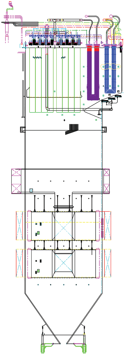
Figure 1: Overall boiler arrangement and burner distribution
The burner configuration consists of distinct zones progressing from upstream to downstream, namely the lower combustion zone, the upper combustion zone, and the secondary overfire air (SOFA) wind zone. Illustrated in Fig. 1, the A, B, and C layer burners correspond to the coal-fired primary air nozzles of the lower burners, while the D, E, and F layer burners represent the coal-fired primary air nozzles of the upper burners. Within the lower burner areas, the coal-fired secondary air nozzles are denoted as AA, AB, AB2, BC1, BC3, and CC, whereas the corresponding nozzles for the upper burners are labeled as DD, DE1, DE3, EF1, EF3, and FF. Additionally, BC2 signifies the fuel secondary air nozzles in the lower burner areas, while DE2 and EF2 represent the fuel secondary air nozzles in the upper burner area. Finally, FF designates the end secondary air nozzle.
The boiler employs the four-corner tangential firing method, with primary burners situated at the four corners of the water wall. Each layer of the boiler features four burners, with each set of four corresponding to a coal mill. Additionally, Ash Wind (SOFA) burners are positioned at the four corners of the water wall above the primary burner area. Currently, the power plant utilizes coal of the designed type, ensuring relatively stable coal quality during operation, closely aligning with industrial analysis and design coal specifications.
In the ultra-low load conditions investigated in this study (15% and 20% load), only two mills, A and B, are operational. Specifically, mill A exclusively burns pure Zhundong coal, while mill B employs a stable blending of Zhundong coal and kaolin at a ratio of 92:8. The industrial coal analysis is detailed in Table 1.

The fluid dynamics calculation software was employed to conduct furnace simulations, utilizing a three-dimensional steady-state approach. The gas phase turbulence was modeled using the mixture-reaction/function method. Non-premixing combustion was simulated using the PDF combustion model, while gas phase turbulence was represented by the standard k-ε turbulence model. The movement of pulverized coal particles of varying types was simulated using a particle random orbit model. For coke combustion, a diffusion-dynamic controlled combustion model was applied. The gas-solid two-phase flow was modeled using the Euler-Lagrange method, while radiative heat transfer was simulated using the P1 radiation model based on the heat flow method to capture the radiative heat transfer processes within the furnace [29].
There is fixed wall temperature boundary condition on the furnace wall. During the iteration, the pressure and speed indicators are mitigated by a SIMPLE algorithm [30]. In addition, all discretization methods have a second-order upwind format.
2.3 Meshing and Computational Scenarios
The geometric model of the solution domain was constructed based on the structural dimensions of the boiler furnace, encompassing the entire furnace as the computational area. The furnace chamber was subdivided and meshed within the burner area to accurately capture flow characteristics, resulting in a total of 3,814,426 grids after conducting a grid-independent test.
A hexahedral hybrid mesh was employed throughout the model. Grid refinement was implemented at the burner outlet height within the main combustion zone, as depicted in Fig. 2.
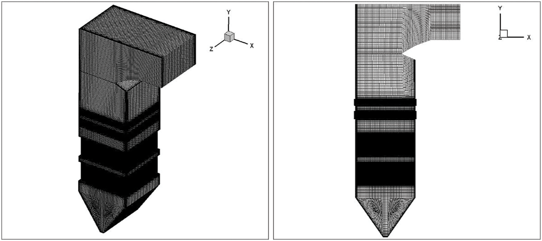
Figure 2: Grid diagram of the heating surface of the boiler furnace
To ascertain the mesh accuracy satisfying the requirements of numerical simulation, grid independence verification was conducted under Boiler Maximum Continuous Rating (BMCR) conditions. Seven sets of mesh configurations with varying grid numbers (1,417,475; 2,126,212; 2,934,173; 3,814,426; and 4,958,753) were evaluated. Flue gas temperature at the furnace outlet height (Y = 72.15 m) was monitored, as depicted in Fig. 3. Notably, at a grid number of 3,814,426, the flue gas temperature stabilizes, indicating grid independence.
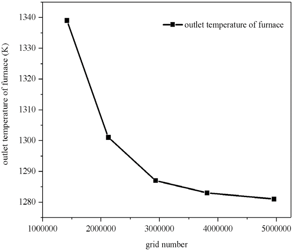
Figure 3: Mesh independent
For both reliability of results and computational efficiency, the mesh with 3,814,426 grids was chosen for further analysis. Verification of the numerical simulation method was conducted by comparing the simulated furnace outlet flue gas temperature (1283 K) with the design value (1228 K), yielding a deviation of 4.5%. This comparison confirms the accuracy of the numerical simulation method within an acceptable range.
The boiler has a rated load of 660 MW, with simulations conducted at 15% and 20% of the rated load. Tables 2 and 3 outlines the specific conditions regarding primary air and coal volume. At 15% load, the secondary air temperature is maintained at 116.2°C, with a total secondary air volume of 189.64 kg/s. For the 20% load condition, the secondary air temperature is raised to 122.5°C, accompanied by a total secondary air volume of 192.12 kg/s.


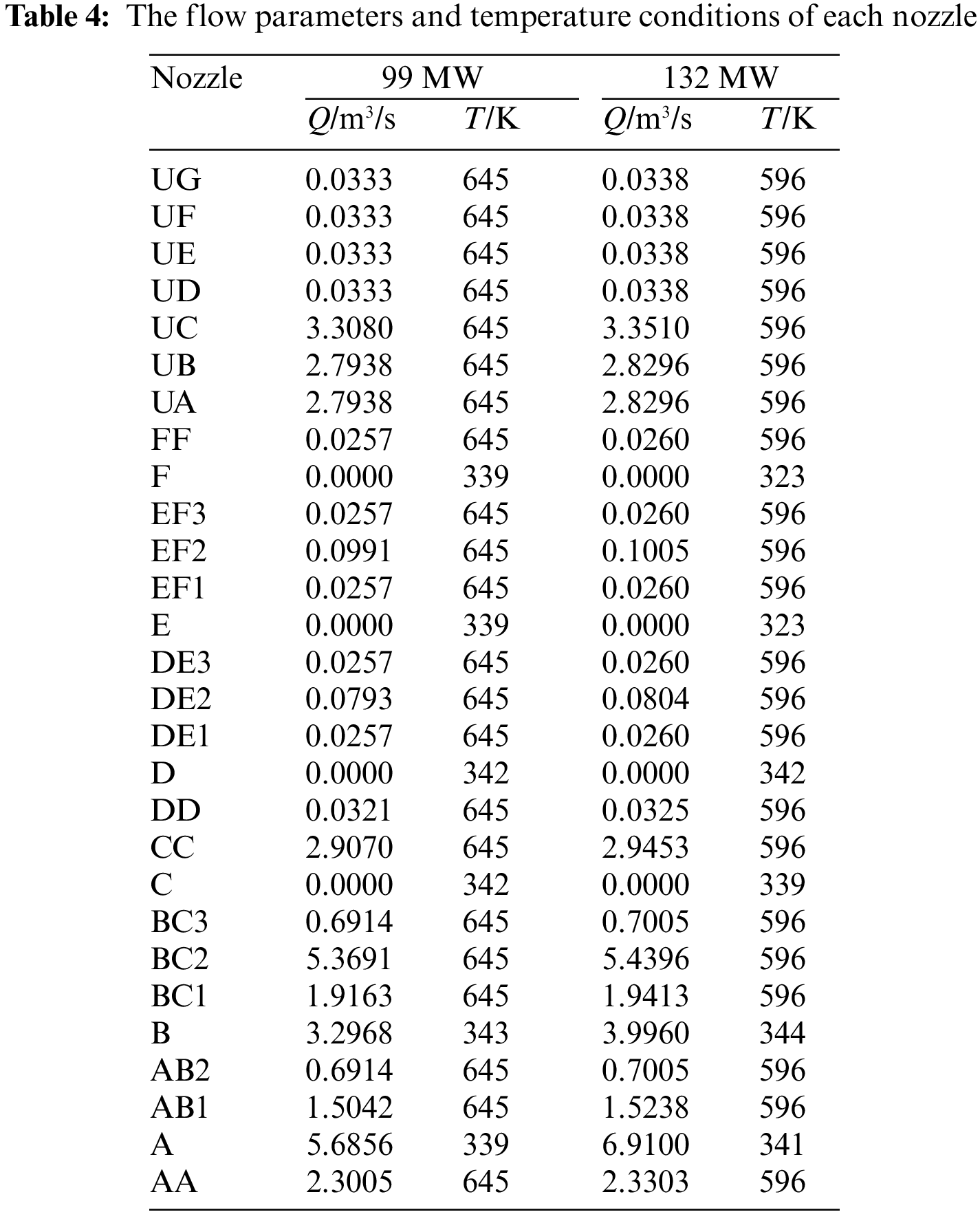
Table 4 shows the flow parameters and temperature conditions of each nozzle.
Wall Boundary Conditions
When pulverized coal is combusted within the furnace, the water-cooled wall surface is assumed to exhibit no velocity slip and no mass permeability. And the boundary condition of the constant temperature without moving the speed the heating surface of the furnace. Particularly in the burner area, temperatures vary significantly, accompanied by high heat flux density. In the simulation, the water wall is modeled as a thermostatic wall, with temperatures assigned based on actual tube wall temperatures. The specific wall temperatures for each area of the furnace chamber are detailed in Table 5.

2.4.1 The Analysis of Velocity and Temperature Field
The analysis of the results mainly includes the analysis of the flow field and temperature field under two ultra-low load conditions, and the average temperature of flue gas at cross section perpendicular along height. Table 6 shows the cross section parameters.

The velocity contour of each feature section under 15% load is shown in Fig. 4. Selecting the longitudinal and transverse sections of the boiler allows the temperature and velocity distribution of the furnace chamber along the height direction to be observed. Layer B (Height Y = 21.2 m), layer C (Height Y = 23.83 m) and the auxiliary wind EF1 layer (Height Y = 31.94 m) and the ember UF layer (Height Y = 45.19 m) are selected, which represent the main combustion area, the upper area and the ember layer of the furnace, respectively. Because the smoke flows from the bottom up, it is representative to choose these four layers for comparison. In addition, cold ash hopper (Height Y = 12 m), CC layer (Height Y = 24.62 m), layer E (Height Y = 31.18 m) and furnace arch (Height Y = 61.54 m) four layers have been added, it gives us a more comprehensive view of the combustion and flow in the furnace.
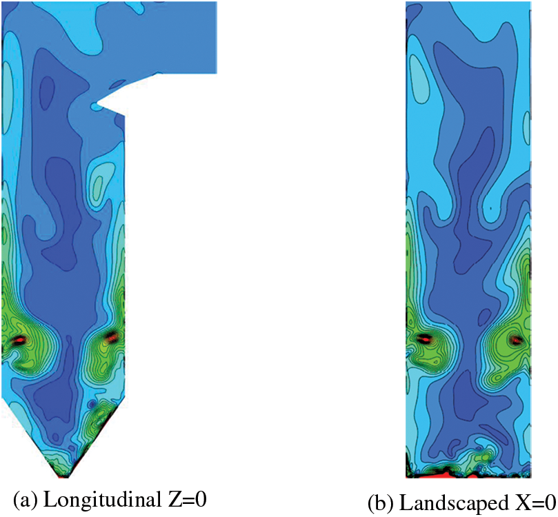
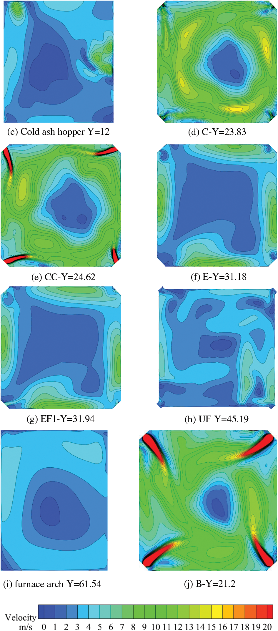
Figure 4: 15% (99 MW) velocity contour
When the boiler is running at 15% load, only the nozzles of two burners, A and B, inject pulverized coal into the furnace. The velocity field cloud diagram of each characteristic section is shown in Fig. 4. In the vertical direction, it can be observed that the velocity of the lower burner region is significantly higher than that of the upper burner region. Additionally, in the B layer, a more pronounced tangential flow is formed, albeit with a slight deviation of the tangent circle from the furnace center. Moving upwards, in the C layer, where no new pulverized coal injection occurs, the velocity is lower compared to the B layer, yet a well-defined tangential flow is maintained. As the height increases, in the EF1 layer, which serves as the auxiliary wind layer with reduced fuel content, velocity distribution becomes notably uneven, resulting in poorer tangential flow formation. Further height increase reveals diminished velocity in the burnout zone of the UF layer, with no formation of a tangential circle observed at this juncture.
Fig. 5 illustrates the temperature contour of each characteristic section under 15% load. It is evident that due to the low temperature of the primary air powder, the pulverized coal undergoes an endothermic heating process upon entering the furnace. Once the temperature of the pulverized coal reaches the ignition point, combustion commences, releasing heat. At 15% rated load, the combustion area of pulverized coal is primarily concentrated near the burner nozzle of the boiler. In the B and C layers, where pulverized coal content is high, combustion heat release is substantial, resulting in higher temperatures and well-defined tangential flow patterns. Conversely, in the EF1 and UF layers, where combustible content decreases, temperatures gradually decline, and tangential flow patterns deteriorate. Within the UF layer, the burnout zone is enriched with oxygen, facilitating further combustion of remaining combustible components in the flue gas. Consequently, some areas within the temperature cloud map exhibit higher temperatures compared to the EF1 layer.
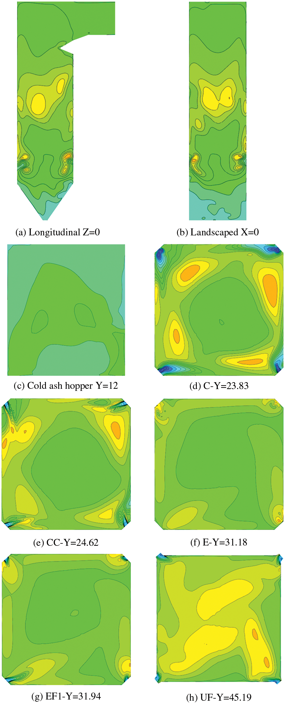
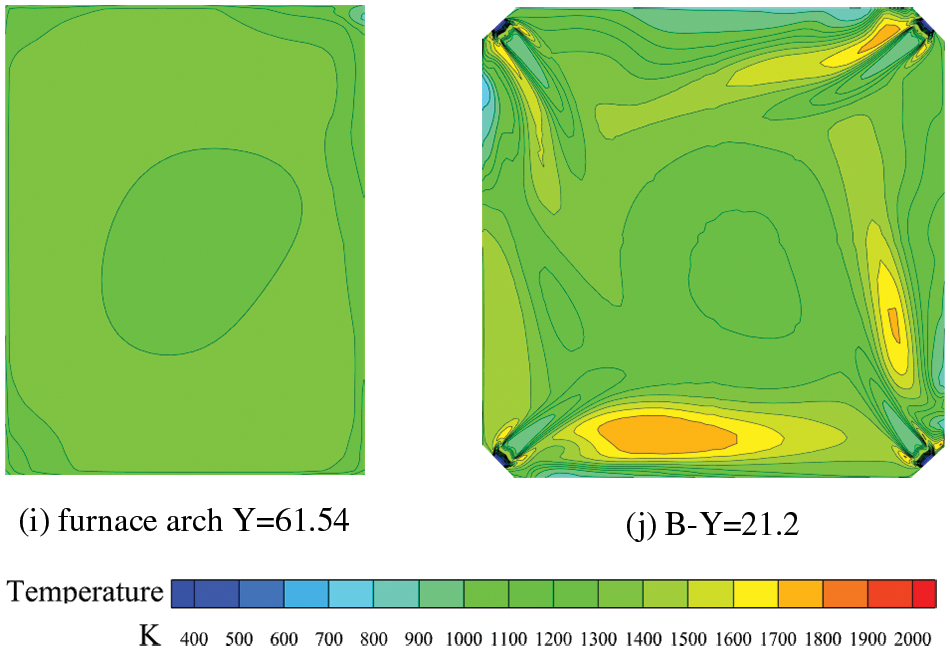
Figure 5: 15% loads (99 MW) temperature contour
Fig. 6 displays the velocity contour of each characteristic section under 20% load. With the boiler load increased to 20%, improvements in flow dynamics within the furnace are evident. Particularly in the burner area of the B layer, flow patterns exhibit a well-defined cut circle, with the position of the cut circle predominantly centered within the furnace. This contrasts with the significant deviation observed at 15% load. The flow characteristics of the C layer closely resemble those of the B layer, demonstrating an enhancement compared to the 15% operating condition. However, in the EF1 and UF layers, flow dynamics deteriorate, resembling conditions observed at 15% load.
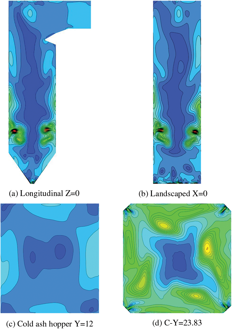
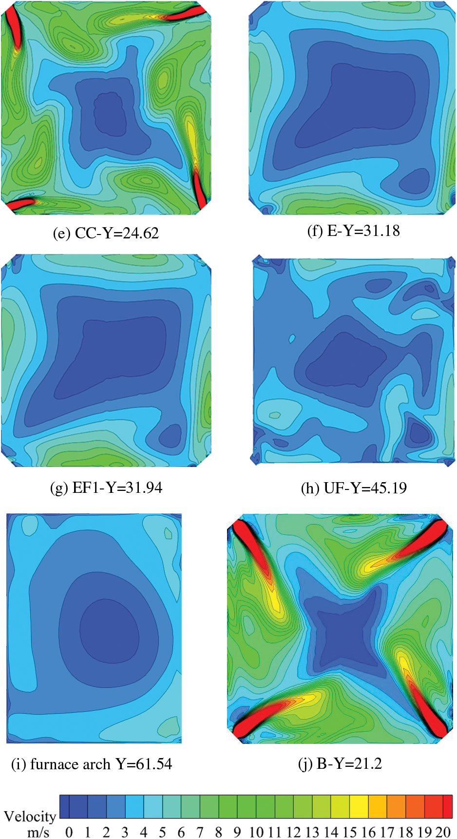
Figure 6: 20% (132 MW) velocity contour
The temperature contour of each feature section under 20% load is shown in Fig. 7. As can be seen from the figure, due to the low temperature of the primary air powder, the pulverized coal has an endothermic heating process after entering the furnace, and after the temperature of the pulverized coal reaches the ignition point, the pulverized coal begins to burn and release heat. As the boiler load increases, it is evident that the combustion temperature area in the furnace is gradually expanding. When the rated load is increased from 15% to 20%, the combustion area in the furnace is increased. At 20% rated load, the combustion area of pulverized coal gradually expands towards the center of the furnace and partially expands with the secondary wind direction to the upper part of the furnace. In the B and C layers, the pulverized coal content is high, and the heat released by combustion is high, so the temperature is higher, and at the same time, it is also a good cut circle. In the EF1 and UF layers, as the combustible content decreases, the temperature gradually decreases, and the cut circle gradually deteriorates. In the UF layer, the burnout area is full of oxygen, and the remaining combustible components in the flue gas are further fully combusted, so that some areas in the temperature cloud map are higher than the EF1 layer.
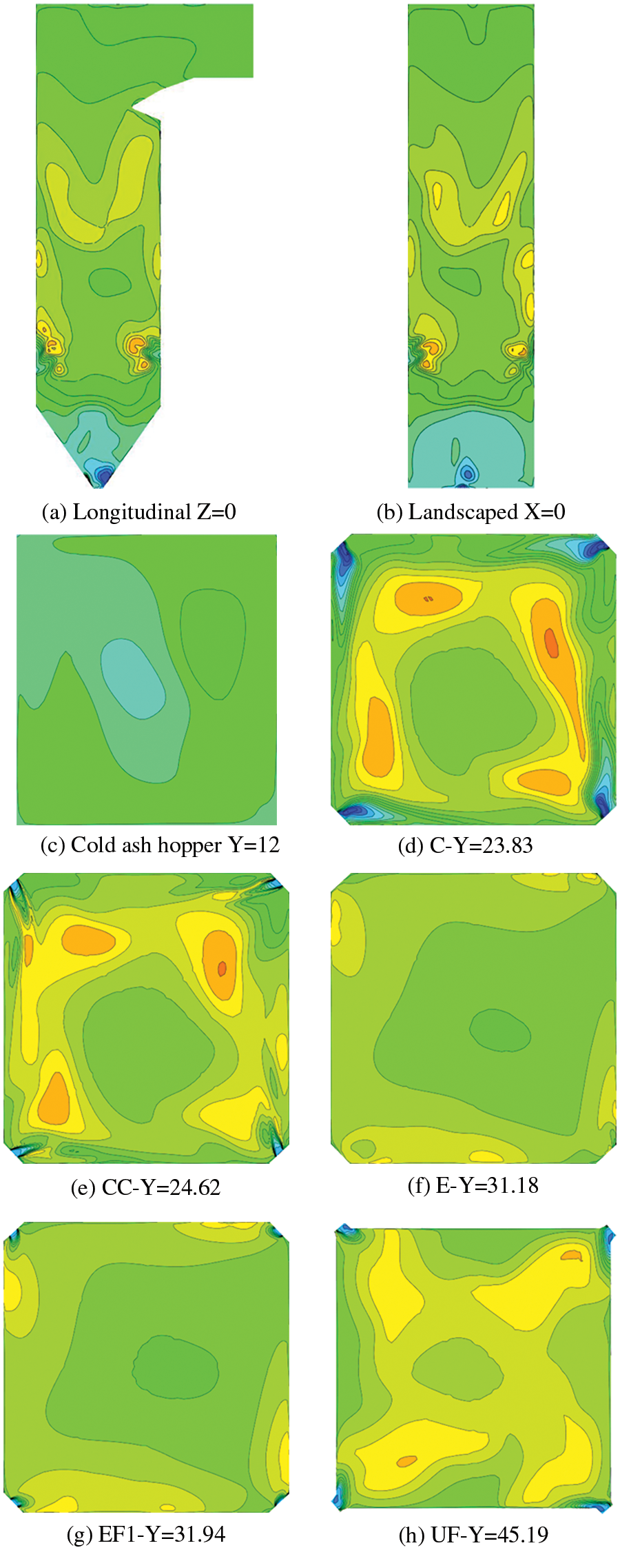
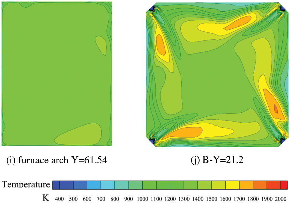
Figure 7: 20% (132 MW) temperature contour
Compared with the 15% working condition, the 20% temperature field has a good improvement, and the temperature gradient appears at the four corners of the B layer furnace with the pulverized coal jet, and the tangent circle formed is significantly improved compared with the 15% working condition. In the C layer, a better cut circle is also formed. In the EF1 and UF layers, the temperature contours are similar to those of the 15% case, but in the UF layer, due to the increase in heat release, they also form a better tangent circle compared to the 15% case.
2.4.2 Variation of Furnace Cross-Section Temperature along Height
Under 15% and 20% low load, the average temperature of flue gas varies with the height of the furnace, as shown in Fig. 8. It can be used to further analyze the detailed variation of the average temperature of flue gas in the furnace along the direction of height.
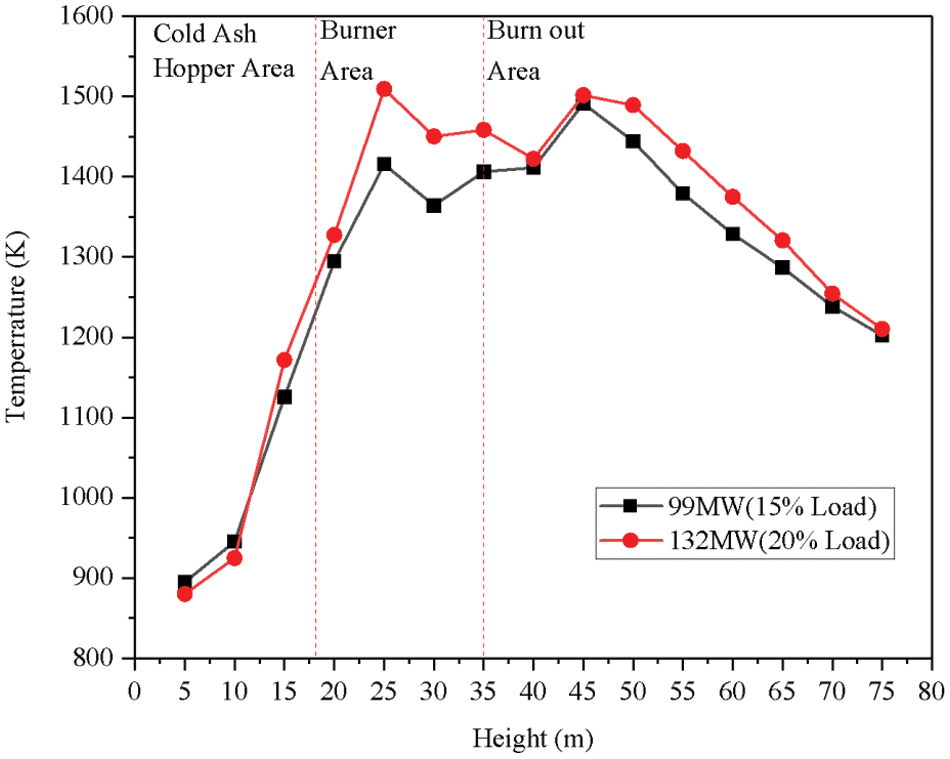
Figure 8: Average flue gas temperature of the upper section along the height of the furnace under two loads
In the direction of the furnace height, the average temperature of the flue gas first increases and then decreases, reaching the maximum value above the burner area, the temperature begins to slowly decrease as the combustion of pulverized coal gradually decreases and the secondary air continues to blow in.
In the cold ash hopper area, the temperatures at both loads exhibit minimal difference. However, notable disparities emerge in the burner area, where the average flue gas temperature under 20% load surpasses that of 15% load by approximately 50 K. In the burning area, we can observe the same situation, the average flue gas temperature at 20% load is still higher than that at 15% load, but the temperature difference between the two conditions is reduced. Interestingly, within the burnout area, both operating conditions display a peak in the average flue gas temperature, which does not follow a simple linear relationship with furnace height. This observation aligns with the earlier analysis of temperature contours. In the burnout area, the presence of burnout wind ensures ample oxygen content in the flue gas, facilitating further combustion of combustible components and subsequent release of heat. As a result, the average flue gas temperature experiences a minor peak within this region before gradually declining due to the absence of combustible components releasing heat.
2.4.3 NOx Concentration Field Distribution
When the boiler operates at 15% and 20% low loads, the NOx concentration distribution in the longitudinal section is shown in Fig. 9. It can be observed that the distribution of NOx under the two loads is similar, and at 15% load, NOx is mainly in the upper part of the furnace. This is attributed to the inability to reach the thermodynamic NOx reaction temperature of 1500 K due to the lower temperature at 15% load. Consequently, NOx generation under this condition is primarily attributed to fuel-type NOx. Additionally, in the burner area, the generation of NOx in the oxygen-deficient combustion state is inhibited, with nitrogen in the fuel decomposing intermediate products and undergoing further oxidation upon contact with oxygen in the upper furnace region. Apart from fuel-based NOx, substantial thermal NOx generation also occurs under 20% load due to higher temperatures. Notably, NOx concentrations are predominantly concentrated near the burner area and the upper portion of the furnace. This observation aligns with the fact that NOx concentration peaks coincide with high-temperature regions, as thermal NOx formation predominantly occurs through oxidation of nitrogen in the air in these areas under 20% load conditions.
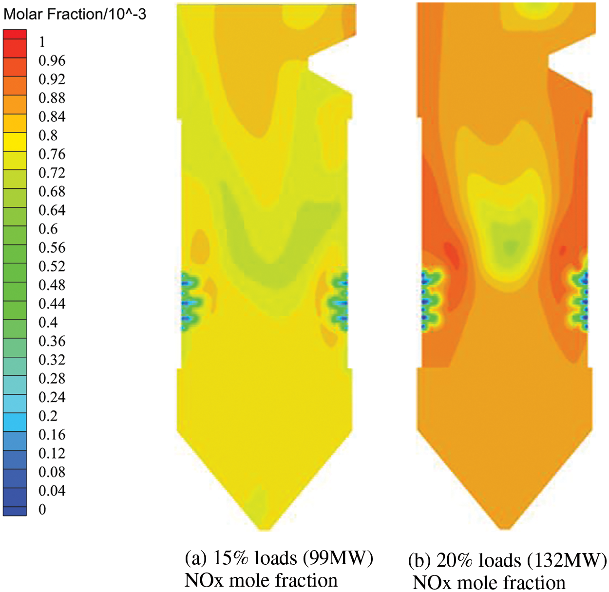
Figure 9: NOx distribution of longitudinal section of boiler under 15% and 20% loads
In response to the evolving demand for flexible operation and deep peak regulation in coal-fired power plants, this study investigates the combustion dynamics within the boiler furnace under low operational conditions. Utilizing a model of a 660 MW square cut round pulverized coal boiler, numerical simulation methods were employed to analyze furnace combustion behavior under two ultra-low load scenarios, namely 15% and 20%, offering valuable insights for practical ultra-low load operations. Key findings include:
(1) The boiler demonstrates operability under ultra-low loads of 15% and 20%, with superior combustion conditions observed at 20% load, characterized by well-defined tangential circles across various furnace sections. Conversely, at 15% load, the integrity of these tangential circles begins to deteriorate.
(2) In comparison to the 15% load condition, the average flue gas temperature within the furnace is generally consistent in the cold ash hopper area, yet exhibits an approximate 50 K elevation in the burner area and a slight increase in the burnout area under 20% load.
(3) The average flue gas temperature exhibits a rapid ascent with height initially, followed by a deceleration in the burner area, where temperature fluctuations become more pronounced.
(4) Notably, the distribution of NOx concentration under the two operational conditions displays distinct patterns. At 15% load, primary NOx emissions, predominantly fuel-derived, are concentrated in the upper central region of the furnace. Conversely, at 20% load, NOx distribution is primarily localized in the high-temperature vicinity adjacent to the burner near the furnace wall.
Acknowledgement: We would like to thank the State Grid Xinjiang Electric Power Research Institute and the School of Energy and Power Engineering of the University of Shanghai for Science and Technology for their support to the research of this paper. And thank the reviewers and editors for their comments on this paper, which has significantly improved the quality of this paper.
Funding Statement: The authors received no specific funding for this study.
Author Contributions: The authors confirm contribution to the paper as follows: study conception and design: Xuehui Jing, Junchen Guo; data collection: Xuehui Jing, Junchen Guo; analysis and interpretation of results: Xuehui Jing, Junchen Guo, Zhiyun Wang; draft manuscript preparation: Xuehui Jing, Junchen Guo, Zhiyun Wang. All authors reviewed the results and approved the final version of the manuscript.
Availability of Data and Materials: The data that support the findings of this study are available from the corresponding author, Zhiyun Wang, upon reasonable request.
Conflicts of Interest: The authors declare that they have no conflicts of interest to report regarding the present study.
References
1. Shao, W., Pan, W., Wang, W., Li, W. (2017). Numerical calculation study on combustion characteristics of four corner tangential coal-fired boilers based on different air distribution methods. Environmental Engineering, 35(6), 73–77. [Google Scholar]
2. Song, S. (2020). Technical analysis of deep peak shaving flexibility transformation for coal-fired power units. Power Equipment Management, 4, 79–81. [Google Scholar]
3. Ouyang, Z., Wang, H., Lv, Q., Zhu, S., Zeng, X. et al. (2023). Progress in deep peak shaving technology for pulverized coal boiler generators. Chinese Journal of Electrical Engineering, 43(22), 8772–8790. [Google Scholar]
4. Wang, R., Zhou, J., Xu, G., Chen, H., Wang, Y. (2023). Optimization of plant level thermal power load distribution under deep peak shaving background. Journal of Power Engineering, 43(2), 185–193. [Google Scholar]
5. Zhang, X., Yang, X., Xin, G., Liu, K., Cui, F. et al. (2022). Deep peak shaving operation test of coal-fired thermal power units. Clean Coal Technology, 28(4), 144–150. [Google Scholar]
6. You, M., Chen, L., Shang, Y., Gao, A., Su, S. et al. (2023). Low load combustion characteristics of supercritical wall tangential boilers. Clean Coal Technology, 29(10), 145–152. [Google Scholar]
7. Sun, L., Diao, Y., Zhao, S., Xu, H., Zhang, R. et al. (2021). Optimization of low load combustion system for 350 MW supercritical wall tangential boiler. Boiler Technology, 52(4), 38–42. [Google Scholar]
8. Ren, B., Liang, L., Yao, L. (2023). Experimental study on low load combustion adjustment of 300 MW circulating fluidized bed boiler. Shanxi Electric Power, 2, 49–52 (In Chinese). [Google Scholar]
9. Ma, D., He, X., Lv, W., Zhang, J., Zhang, S. (2022). Research on low load stable combustion characteristics of 660 MW supercritical W-flame boiler. Journal of Engineering Thermophysics, 43(1), 259–266. [Google Scholar]
10. Liu, L. (2009). Numerical simulation of combustion and air distribution in a four corner tangential coal powder furnace. Dalian, China: Dalian University of Technology. [Google Scholar]
11. Wang, Z., Zhuo, Y., Yang, M. (2014). Numerical simulation of natural convection of double diffusion in open square cavity. 2014 Annual Meeting of Chinese Society of Engineering Thermophysics, Xi’an, China. [Google Scholar]
12. Cheng, H., Wen, L., Song, Z. (2015). Low nitrogen combustion transformation and parameter optimization design of 350 MW coal powder boiler. Journal of Power Engineering, 35(9), 704–708. [Google Scholar]
13. Jin, W., Si, F., Cao, Y., Yu, C., Wang, J. (2023). Numerical research on ammonia-coal co-firing in a 1050 MW coal-fired utility boiler under ultra-low load: Effects of ammonia ratio and air staging condition. Applied Thermal Engineering, 233, 121110. [Google Scholar]
14. Chang, H. (2021). CFD modeling of hydrodynamics, combustion and NOx emission in a tangentially fired pulverized-coal boiler at low load operating conditions. Advanced Powder Technology: The Internation Journal of the Society of Powder Technology, 32(2), 290–303. [Google Scholar]
15. Sun, W., Zhong, W., Yu, A., Liu, L., Qian, Y. (2016). Numerical investigation on the flow, combustion, and NOX emission characteristics in a 660 MWe tangential firing ultra-supercritical boiler. Advances in Mechanical Engineering, 8(2), 1. [Google Scholar]
16. Yuan, L., Zhong, W., Chen, X. (2019). Three-dimensional numerical simulation of variable load combustion in supercritical pulverized coal boiler for deep peak shaving. Journal of Southeast University: Natural Science Edition, 49(3), 7. [Google Scholar]
17. Ti, S., Kuang, M., Wang, H. (2020). Experimental combustion characteristics and NOx emissions at 50% of the full load for a 600-MWe utility boiler: Effects of the coal feed rate for various mills. Energy, 196, 117128.1–117128.8. [Google Scholar]
18. Zhang, X., Chen, Z., Zhang, M. (2021). Combustion stability, burnout and NO emissions of the 300-MW down-fired boiler with bituminous coal: Load variation and low-load comparison with anthracite. Fuel, 295(11), 120641. [Google Scholar]
19. Wang, Q., Chen, Z., Li, L. (2020). Achievement in ultra-low-load combustion stability for an anthracite- and down-fired boiler after applying novel swirl burners: From laboratory experiments to industrial applications. Energy, 192, 116623.1–116623.19. [Google Scholar]
20. Du, H., Li, Z., Liu, Z., Zhang, M., Huang, C. et al. (2022). Industrial measurement of combustion and NOx formation characteristics on a low-grade coal-fired 600 MWe FW down-fired boiler retrofitted with novel low-load stable combustion technology. Fuel, 321, 123926. [Google Scholar]
21. Qiao, Y., Li, S., Jing, X., Chen, Z., Fan, S. et al. (2022). Combustion and NOx formation characteristics from a 330 MWe retrofitted anthracite-fired utility boiler with swirl burner under deeply-staged-combustion. Energy, 258, 1. [Google Scholar]
22. Ma, D., Zhang, S., He, X., Zhang, J., Ding, X. (2023). Combustion stability and NOX emission characteristics of a 300 MWe tangentially fired boiler under ultra-low loads with deep-air staging. Energy, 269, 15. [Google Scholar]
23. Yu, J., Lee, B., Oh, D., Jeon, C. (2021). Optimization of operating conditions to achieve combustion stability and reduce NOx emission at half-load for a 550-MW tangentially fired pulverized coal boiler. Fuel, 306, 121727. [Google Scholar]
24. Jiang, Y., Lee, B. H., Oh, D. H., Jeon, C. H. (2022). Influence of various air-staging on combustion and NOX emission characteristics in a tangentially fired boiler under the 50% load condition. Energy, 244. [Google Scholar]
25. Bolegenova, S., Askarova, А., Georgiev, A., Nugymanova, A., Maximov, V. et al. (2024). Staged supply of fuel and air to the combustion chamber to reduce emissions of harmful substances. Energy, 293, 130622. [Google Scholar]
26. Wang, Y., Zou, Z., Lu, K., Li, Q., Li, L. (2024). Probing of operation economy for coal-fired unit under low loads with two fixed boundary conditions. Energy, 288, 129710. [Google Scholar]
27. Wang, H., Jin, H., Yang, Z., Deng, S., Wu, X. et al. (2024). CFD modeling of flow, combustion and NOx emission in a wall-fired boiler at different low-load operating conditions. Applied Thermal Engineering, 236, 121824. [Google Scholar]
28. Chen, Z., Yuan, Z., Wang, Y., Li, Z. (2023). Experimental study of gas-particle flow in the coal-fired industrial boiler applied radial air staging at variable over-fired air distributions. Fuel, 354, 129315. [Google Scholar]
29. Cheng, H., Wen, L., Song, Z. (2015). Reconstruction and parameter optimization design of low nitrogen combustion of 350MW pulverized coal boiler. Journal of Power Engineering, 35(9), 704–708. [Google Scholar]
30. Kong, Z., Wang, Z., Yang, M. (2019). Numerical simulation of double diffusion natural convection in a square open mouth. Energy Engineering, 3, 14–20. [Google Scholar]
Cite This Article
 Copyright © 2024 The Author(s). Published by Tech Science Press.
This work is licensed under a Creative Commons Attribution 4.0 International License , which permits unrestricted use, distribution, and reproduction in any medium, provided the original work is properly cited.
 Downloads
 Citation Tools