
 Submit a Paper
 Propose a Special lssue
 Open Access
ARTICLE
Experimental and Numerical Investigation of the Performance of Turbulent Heat Transfer in Tubes with Different Cross-Sectioned Wire Coils
Department of Mechanical Engineering, College of Engineering, Mustansiriyah University, Baghdad, Iraq
* Corresponding Author: Ali Shokor Golam. Email:
(This article belongs to the Special Issue: Passive Heat Transfer Enhancement for Single Phase and Multi-Phase Flows)
Frontiers in Heat and Mass Transfer 2024, 22(2), 633-653. https://doi.org/10.32604/fhmt.2024.050218
Received 31 January 2024; Accepted 18 March 2024; Issue published 20 May 2024
 View Full Text
 Download PDF
Abstract
The thermal-hydraulic performance of plain tubes with and without wire coils in turbulent regimes is investigated experimentally and numerically. The effects of wire coil distribution (circular cross section) within the tube were explored experimentally, and water was employed as the working fluid. The numerical simulation was carried out using software programmer ANSYS Fluent 2019 R3 using the finite-volume approach. In the turbulent regime, six cross-sectioned wire coils were analyzed, including: circular, rectangular, hexagonal, square, star shape, and triangle. The utilization of a tube with a wire coil has been shown to increase heat transfer rate and pump consumption. The results indicate a high level of concurrence, as the deviations are all below 8%. Compared with plain tube, the wire coils, according to the arrangement (TWD), gave the best PEC. The heat transfer enhancement ability of different cross sections follows the following order: StCS > RCS > HCS > SqCS > CCS > TCS. Also, the sequence of pump consumption for each cross section is as follows: RCS > StCS > SqCS > HCS > CCS > TCS.Keywords
Nomenclature
| Re | Reynolds number |
| Nu | Nusselt number |
| Nup | Nusselt number for plain tube |
| Mass flow rate (kg/s) | |
| Tube diameter (m) | |
| di | Internal tube diameter (m) |
| u | Velocity of the fluid (m/s) |
| Heat transfer coefficient (W/m2.K) | |
| Friction factor | |
| Friction factor for plain tube | |
| Specific heat (kJ/kg.K) | |
| V | Electric voltage (V) |
| I | Electric current (A) |
| Water inlet temperatures (K) | |
| Water exit temperatures (K) | |
| Tsi (z) | Inner wall temperature at a distance z (K) |
| T (z) | Water temperature at a distance z (K) |
| Greek Symbols | |
| μ | Dynamic viscosity (Pa.s) |
| Thermal conductivity (W/m.K) | |
| Superscripts | |
| FWD | First wire coil distribution |
| SWD | Second wire coil distribution |
| TWD | Third wire coil distribution |
| PVC | Polyvinyl chloride |
| PEC | Performance evaluation criterion |
Heat transfer mechanisms are regarded as fundamental components of all systems in the industrial sector. Energy conservation and heat exchanger size reduction are two methods that can be employed to enhance the thermal efficacy of such systems. Given that the heat transfer in a single conduit (channel) serves as a proxy for the performance of the entire device, it is frequently possible to assess the effectiveness of a heat exchanger by looking at that channel. Many experimental and numerical studies were reviewed, the most important of which are: Kongkaitpaiboon et al. [1] conducted experiments on a ring-shaped tube wall insert. He focused on a small range of Re values (4000 to 20000) and investigated three different inner ring diameters and three different distances between them (longitudinal and radial dimensions). According to his findings, the most effective heat transfer occurred with the lowest inner diameters and the closest ring spacing. An experimental research for improving heat transfer in a tube using delta-winglet twisted tape inserts was conducted by Eiamsa-ard et al. [2]. Compared the results of configurations with S-DWT (straight) and O-DWT (oblique) delta-winglet twisted tape. They found that the O-DWT is superior to the S-DWT in terms of heat transfer efficiency. Srivastava et al. [3] looked at using conical frustums d/D = 0.3 as turbulators. Divergently arranged conical inserts (DR configuration) including both drilled and undrilled options. The inserts, the results show, successfully mix fluids of varying temperatures in the core and along the wall. At a Reynolds number of 6258, it is demonstrated that the perforated conical insert in the diverging arrangement (PDR) with d/D = 0.3, p/D = 2, x/L = 0.5, and N = 4 achieves a maximum thermo-hydraulic performance of 1.38. Hosseinnejad et al. [4] studied the effect of twisted tape on heat exchanger flow parameters. At increasing Reynolds numbers, the twisted tape torsion ratio falls while the Nusselt number increases. As a result, heat transport may be improved across a smooth tube. Wijayanta et al. [5] used short-length twisted strip inserts to examine the heat transfer increase of single-phase flow in a tubular heat exchanger. Twisted tape length ratio (0.25, 0.5, 0.75, 1). The twisted tapes are made of aluminum with a width of 12.6 mm, a pitch of 35 mm and a thickness of 0.7 mm. The Reynolds numbers that were applied in the study ranged from 4500 to 18500. The results showed that increasing the length of the tape contributes to increasing heat transfer and that the largest average Nusselt number obtained in the study was 0.51 times greater than that of a plain tube. Heat transfer in a heat exchanger with concentric dimple tube was studied by Vignesh et al. [6]. They noticed that the total heat transfer coefficient inside and outside of the tube was between 56% and 64% more than that of concentric plain tube. Additionally, by around 55%, the efficacy parameter exceeded concentric plain tube. Experimentally, Jafari et al. [7] examined the effect of undulating flow injection on the heat transfer efficacy of the tube. Three-lobed twisted coil tube constitutes the generator’s cross-section. In order to evaluate the heat transfer efficacy of the proposed thermal system, the Nusselt number and friction factor were regarded as the desired outcomes. Singh et al. [8] proposed including tapered wire coils in a double-tube heat exchanger to improve heat transfer. The effect of using tapered wire coils (convergent (C), divergent (D) and convergent-divergent (C-D)) on the thermal behavior of the hest exchanger was investigated. The results showed that using type (D) wire coil gave the best thermal performance compared to types (C) and (C-D). According to Zhang et al. [9] predictions, tubes equipped with four different widths of helical screw-tapes (w = 7.5, 12, 15, and 20 mm) will exhibit heat transfer flow friction and thermal performance characteristics. Due to the ideal trade-off between gains in heat transfer and friction penalties, the simulation results show that the helical screw-tape with w = 15 mm offers the best overall heat transfer performance. Flow characteristics of a newly constructed helical coil heat exchanger were investigated by Wang et al. [10]. After every half-turn, the helical coil included a plastic reversed loop, increasing the area over which the flow was distributed. The heat transfer was greatly improved due to the curvature of the inverted loops. They demonstrated that simply switching the direction of the loops, the heat transfer rate could be increased by 20% with no appreciable loss in pressure. Gholamalizadeh et al. [11] studied numerically the heat transfer and pressure drop in a helically coiled tubular heat exchanger with a coiled wire insert. The effect of the diameter and cross-sectional shape of the wire on the Nusselt number and coefficient of friction was studied. The results showed that coiled wires with circular cross-section gave the best improvement to the Nusselt number and friction factor by 340.9% and 536.1%, respectively. Bhuiya et al. [12] examined the effects of helical tape inserts with varying helix angles (9°, 15°, 21°, and 28°) on pressure drop and heat transfer. The findings show that lowering helix angles improve the Nusselt number, friction factor, and thermal enhancement efficiency. Using the double helical tape insert with a 9° helix angle at a high Reynolds number results in the best thermal performance. Heat transfer in a tube with laminar flow was investigated by Guo et al. [13], who compared centre-cleared twisted tape, short-width twisted tape, and regular twisted tape. It has been shown that the resistance and heat transfer coefficient may be reduced using a short-width twisted tape by reducing the disturbance in the flow boundary layer. That is why reducing the breadth of the twisted tape has a negative effect on the tube’s overall performance. Center-cleared twisted tape improved tube performance by 1.07 to 1.20 times at a hollow ratio of 0.3 compared to conventional twisted tape. A numerical study on a tube with twisted tapes and a poor fit was done by Eiamsa-ard et al. [14]. They used four turbulence models, and their findings showed that the SST k-turbulence model correlates with measurement data more strongly than the other models. Ibrahim et al. [15] took a look at a compilation of earlier experimental and computational investigations on various twisted tape inserts that might increase heat transfer rates. According to preliminary findings, twisted gaskets were successful in improving heat transfer inside the pipe for both laminar and turbulent flow. However, owing to flow obstruction in turbulent flow, tortuous tapes caused pressure loss more than laminar flow did. Chang et al. [16] conducted an experiment to compare the performance of heat exchangers using polygonal twisted bands with and without slits. The results showed that the thermal performance of the improved version far exceeds that of ordinary twisted tapes. Skullong et al. [17] analyzed numerically how perforated tapes with staggered airfoils affect the thermal performance of turbulent fluid flow through heat exchanger tubes. They discovered that the thermal performance factor could be increased to 1.71 by using a perforated bar with a pitch ratio of 1.0 and an occlusion ratio of 0.15. Thianpong et al. [18] evaluated parallel-winged perforated twisted tapes (PTT) to determine their effect in enhancing heat transfer through a heat exchanger tube. The results showed that the holes reduced friction due to the small contact area, while the wing shapes improved mixing along the wall. Saha et al. [19] studied the heat transfer properties and friction factor of rough circular channels and helical spiral strip. The results indicate that the performance of the helical strip with integrated helical rib roughness significantly outperforms that of the single optimization technique. Fan et al. [20] recently conducted experiments using the identical experimental setup and working fluid and found that twisted tape with holes increased heat transfer rates by 10.5%. Shelare et al. [21] reviewed previous studies on the use of different types of twisted tapes to enhance heat transfer. The paper revealed future research on twisted tapes which will further the remarkable improvement in heat exchanger device as well as give scope for various variable approaches for new advances in heat transfer improvement. Singh et al. [22] conducted an experimental study to investigate the hydrothermal behavior of a double tube heat exchanger to evaluate the effects of inserting wire coils and twisted tapes. The working fluid was an Al2O3+MWCNT hybrid Nano fluid. The results showed that the inserting of type D wire coils gave the best heat transfer performance compared to other types. Also, the heat transfer coefficient and pressure losses increase as the twisted tape width and twisting ratio decrease. Twisted tapes with a V-cut shape also show a higher performance index than wire coils. Xiong et al. [23] investigated the effects of conical and spindle motors on heat transfer and turbulent flow designs in a double-tube heat exchanger (DPHE). The results show that employing a heat exchanger with a circular inner tube provides for the maximum convective heat transfer coefficient. Furthermore, it has been shown that changing the shape of the conical to spindle generators improves the heat exchanger performance index (HE). Qasim et al. [24] investigated the thermal and hydraulic properties of a circular tube equipped with conical wire coils experimentally and numerically. The governing equations were solved using the tool ANSYS-Fluent (2019 R3). The experimental activity included designing and fabricating a test bench for experimental measurements. In comparison to a conventional tube, the findings indicated that using a class A5 cone wire coil resulted in the greatest increase in heat transmission. Ahmad et al. [25] used the CFD techniques to investigate heat transfer increases in a double-tube heat exchanger (DPHE) with corrugation on the inner tube, helical wire coil insertion, or both. The water mass flow rate was chosen to have a Reynolds number of 10000–15000. With an impediment or changed surface, heat transmission increased significantly. Corrugation on the tube increased the Nusselt number by 7% with a 23% increase in friction, while wire coil and corrugation and wire coil increased the number by 4.5% and 8%, respectively, with 374% and 386% friction increases, which require a lot of pumping power. Chompookham et al. [26] developed a novel wire coil (serrated wire coil (SWC)) to have different characteristics. (SWC) was inserted into test tubes with three different coil diameters (DC) of (34.4, 41.2, and 47.9) mm and four different coil lengths (PC) of (10, 20, 30 and 40) mm. It was observed that the maximum thermal performance improvement factor (η) for this work was about 1.41 for SWC with DC = 47.9 mm and PC = 10 mm at Re = 5114. Du et al. [27] presented experimental investigations on the thermal and turbulent flow characteristics in a traverse corrugated tube (TCT) equipped with regularly spaced wire coils of gradually varying widths (WCs-GVW). Three arrangements including divergent WC arrangement (DWC), convergent WC arrangement (CWC) and convergent-convergent WC arrangement (DCWC) were considered and five space ratios were considered at S/D = 0.60, 1.55, 2.97, 5.34 and 10.09. The main findings are that the CWC arrangement has the lowest PEC, Nu and f ratio in the DWC range with reduced area ratio. In contrast to the normal tube, Nu in TCT with WCs−GVW increases approximately 1.74–2.26 times while f is in the range of approximately 4.18–10.68 times.
In the above-mentioned literature, extensive studies have been carried out on the topics of improving the thermal and hydraulic performance of heat exchangers. Complex mechanisms related to heat transfer phenomena were used while inserting turbulence into the flow path, such as twisted taps, extended surfaces, fluid additives, etc., wire coils, one of the most promising heat enhancement elements. There is a need for more in-depth analysis of the techniques of using wire coils as turbulent bodies for flow inside tubes. However, the influence of the wire coil cross section shape has yet to be documented. The current effort focuses on three important challenges with wire coil performance: (1) Three various wire coil distributions (circular cross section) within the tube are experimentally studied to determine the optimal distribution to improve heat transfer performance. (2) The influence of cross-section shape is investigated numerically for six distinct wire coils. (3) Discuss the mechanisms of fluid flow and heat transfer characteristics to describe the heat transfer processes of tube and wire coils.
The present part describes the experimental test rig and provides a simple description of the devices used. Fig. 1 shows the test experimental rig, as many parts were carefully manufactured to prevent any leakage of liquids during the experiment. All parts are installed on a metal frame and insulated to prevent heat dissipation. The centrifugal water pump operating at a constant voltage of 220 V and 2.5 A, Qmax = 30 L/m, and h-max = 30 m is the other crucial components needed to construct the test rig. Five K-type thermocouples were also added to the test rig, two additional thermocouples are inserted at the inlet and outlet of the test section to monitor the water’s temperature, while three thermocouples are installed along the tube with a spacing of 250 mm between each thermocouple. The K-type thermocouple provides a temperature measurement range from −100 to 1300°C, with a standard accuracy: +/−2.2°C or +/−0.75%, Special Limits of Error: +/−1.1°C or 0.4%. To detect temperatures and record the measurements over time, all thermocouples were linked to the 4-channel data recorder HT-9815, with temperature range: −200 to 1372°C, accuracy: >100°C: ± 1°C). Due to their flexibility and simplicity in re-installation after repair, polyvinyl chloride (PVC) tubes with a diameter of 12 mm were used to link all of the components of the tester using a single flow meter (type-LZS). The working fluid (water) tank is a stainless steel tank made of 90 cm high and a diameter 60 cm with a capacity of 200 L, and it is used to supply the cold liquid to the pump and then to the heat exchanger.

Figure 1: Experimental test rig
The test section is a copper tube with an inner diameter of 22 mm and a length of 1 m. The outer surface of the tube is electrically heated by a tungsten coil of 3 m length and diameter of 1.5 mm with a heating power of 3000 W, which is wound over an electrical insulator distributed along the length of the tube to generate a uniform heat flow as shown in Fig. 2. In addition, the test rig was equipped with Variac transformer 3000 W to adjust the power. In this study, the performance of the circular tube and the effect of wire coils distributed were examined by changing the water flow rates with multiple heat flux on the surface of the tube, while the water inlet temperature and operating conditions were stable in all experiments.

Figure 2: Test section
The main goal of the present experimental study is to conduct an experimental analysis to compare the distributed of the wire coils that circular cross section within the flow path to achieve the best performance evaluation criterion (PEC). Fig. 3 shows three ways to distribute wire coils within the flow path. The first distribution of the wire coil includes inserting wire coil with a length 750 mm, coil diameter 20 mm, wire coil diameter 2 mm and pitch coil 5 mm. the first wire coil distribution (FWD) symbolizes. The second wire coil distribution (SWD) represents the use of five coils wire with a length of 150 mm distributed along the length of the tube, while the third wire coil distribution (TWD) includes ten coils wire coils with a length of 75 mm. The specifications of other wire coils, coil diameter, coil wire diameter and pitch, are the same.

Figure 3: Wire coil distribution
By experimentally simulating a circular horizontal tube with a constant heat flow on its outer surface, it was able to analyses the efficiency of the present heat exchanger.
2.2.1 Tube Internal Heat Transfer Coefficient and Fraction Factor
Using the following formula [28], electrical power may be applied to the tube’s exterior:
Calculating how much heat is delivered from the heating wire to the distilled water is done using the following formula:
Before doing any calculations, it is essential to understand the water’s heat transfer coefficient. Calculating the local heat transfer coefficient is as follows:
The following equation has been used to compute the local Nusselt Number:
Kármán-Prandtl’s resistance equation for turbulent flow in smooth tubes provides a definition of the friction factor and may be used to simulate the change of the friction factor with Re when the tube surface is smooth [29].
The criterion of the performance evaluation criterion (PEC) is the basis of comparison for each addition to improve heat transfer in heat exchangers. The increase in the amount of heat transferred through the pipes is not considered an improvement unless it is compared with the friction factor that causes a decrease in pressure due to the addition of any specific object intended to improve heat transfer [30].
The first experiment tested a tube without inserting wire coils. After making sure that there is no water leakage, the pump is started and the water flow rate is determined by the valves. All tests are performed under fully developed turbulent flow with a Reynolds number range (3000–5000). After that, the amount of voltage entering the heater is determined by variac transformer and according to the heat flux required to be applied to the surface of the tube (1000–2500) W/m2. The thermocouple readings are observed at the inlet and outlet of the test section and along the tube until a steady state is reached. After completing the experiments for the plain tube, one of the wire coil arrangement is inserted into the tube and the mentioned test steps are repeated.
The material of the tube is copper. The smooth circular tube has the following dimensions: length 1 m, wall thickness 1.5 mm, and inner diameter 22 mm. In this paper, the geometric values of the tube are presumed to be constant. Fig. 4 illustrates the schematic diagram of the physical model. Water is the operational fluid. Water is assumed to be continuous, Newtonian, and isotropic. The negligible impact of thermal radiation and viscous heating is attributed to the low temperature. The effect of gravity is disregarded. Assumed to be constant are the thermal-physical properties of water: ρ = 998.2 kg/m3, λ = 0.6 W/(m.K), Cp = 4182 (J/Kg.K) and μ = 0.001003 (Pa.s).

Figure 4: Schematic of physical model
Design Considerations: Selection of the cross-section shape of a threaded wire coil depends on various factors, including specific heat transfer requirements, fluid properties, pressure drop constraints, and manufacturing considerations. Computational fluid dynamics (CFD) simulations or experimental studies can be performed to optimize the shape and dimensions of a threaded wire coil for a specific application. It is important to note that the effect of cross shape on heat transfer is only one aspect of the overall heat transfer performance of threaded wire coil heat exchangers. Other factors such as wire coil diameter, pitch, and tube material properties play important roles in determining the overall heat transfer properties. The numerical study focuses on the performance of a tube in which wire coils of different cross-section are inserted and compares the characteristics of the flow structure, heat transfer and friction factor. The distribution of wire coils inside the tube depends on the results of the experimental side of the current study. Five different shapes for the cross-section of the coil wire were proposed in addition to the circular cross-section of the conventional coil wire that was used in the practical aspect because it is available locally. The proposed cross section shapes included: Hexagonal cross section (HCS), Star cross section (StCS), Rectangle cross section (RCS), Square cross section (SqCS), and Triangle cross section (TCS). The cross-sectional area of all proposed shapes is 3.14 mm2. The sketch of different cross section of wire coil is shown in Fig. 5.

Figure 5: Different wire coil cross-sections
The following are the stable mathematic equations for continuity, momentum, and energy:
Continuity equation:
Momentum equation:
Energy equation:
where T and p stand for fluid temperature and pressure, respectively; u is the fluid velocity;
The conventional k−ω turbulence model is used in the numerical simulation. The two equations in question are the turbulent kinetic energy (k) and dissipation rate (ω) equations.
Standard k−ω model:
The variables ρ, t,
Fluent 2019 R3, a commercial 3D double-precision CFD program, solves the whole simulation task. As shown in Fig. 6, polyhedral mesh is used to provide high-grade mesh. The momentum and energy equations use the second-order upwind technique. For the pressure, the second-order difference method is used in order to get a precise and stable solution. The SIMPLE method is connected to pressure and velocity. The velocity inlet is utilized to apply a uniform temperature of 300 K, which is the ambient temperature of water. Utilizing inlet velocities calculated from Reynolds numbers between 3000 and 5000, one can determine the variation in heat transfer performance at various Re. Applying pressure to the outlet constitutes the outlet. The boundary condition of no-slip is enforced. Assume that the surfaces of the wire coil are adiabatic. With the exception of the energy equation, which must be below 1 × 10⁻⁶, the convergence criterion stipulates that the normalized residuals for mathematical equations must be less than 1 × 10⁻⁴.
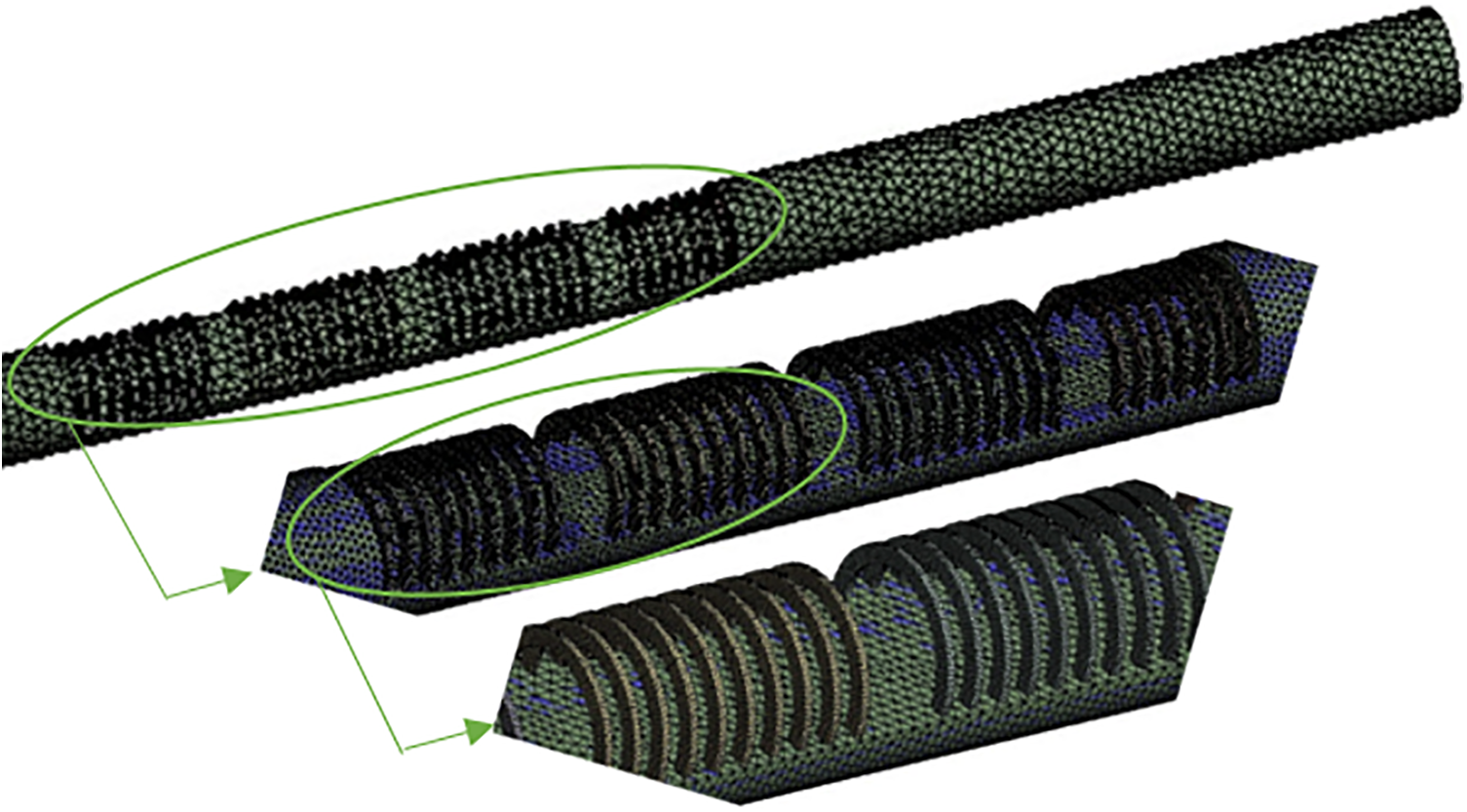
Figure 6: Mesh created
4.1 Experimental and Numerical Models Rapprochement
Fig. 7 compares the numerical results of the Nusselt number with the experimental results for plain tube with and without circular wire coil (TWD) at a heat flux of 2000 W/m2 in order to validate the numerical procedure described above. It is evident that the CFD results are in excellent accord, as the Nusselt number deviate by less than 8% and 7%.

Figure 7: (Nusselt-Reynolds) number data rapprochement
The results of the current study will provide useful information’s that helps in thermal designing, selecting the best cross section shape for wire coil and the wire coil distribution mechanism within the flow path. Fig. 8 shows the effect of changing the Reynolds number on the value of the Nusselt number before and after inserting the wire coil. It can generally be observed that the value of the Nusselt number increases as the Reynolds number. It was found that the studied wire coil have a significant impact on the Nusselt number when compared to a plain tube at the same Reynolds number and the heat flux. This is due to the fact that the wire coil and distribution inside the tube generate a torsional flow of water, which enhances the mixing of water and contact with the walls of the inner tube. However, the nature of the flow created within the tube and its influence on heat transfer from the surface of the tube to the water causes disparity in the effect of the wire coil and distribution on Nusselt number values. Under a constant applied heat flux along the outer surface of the tube 2500 W/m2 and a Reynolds numbers range of (3000–5000), it can be observed that the value of the Nusselt number when compared with a plain tube increases by 67% when inserting the FWD and the percentage reaches to 73% and 82% when inserting (SWD and TWD), respectively.

Figure 8: Nusselt number and Reynolds number variations for different wire coil distribution
Fig. 9 shows the variation of Nusselt number ratio (nu/nup) with Reynolds number for different wire coil distributions. It is obvious that the method of distributing the wire coils inside the tube has a clear effect on the value of (nu/nup) at different values of the Reynolds number. It can be seen that the (TWD) gave the highest value of (nu/nup) for all values of the Reynolds number. This is attributed to the fact that the distribution of wire coils on the fluid flow behavior inside the test tube causes a more turbulent flow and thus contributes to increasing the heat transfer efficiency. It can be conclude that the wire coil distributions greatly affect the behavior of the fluid flow and the efficiency of heat transfer, and from the results of the aforementioned figure, it can be notice that using the TWD wire coil distribution in applications that require heat transfer is more effective.

Figure 9: Variation of the Nusselt number ratio (Nu/Nup) with Reynolds number for different wire coils distribution
Fig. 10 depicts the relationship between the friction coefficient and the Reynolds number before and after inserting the wire coil. In general, because a rise in the Reynolds number increases the velocity and overcomes the viscous pull of water, the shear between the water and the pipe walls diminishes, and the friction factor decreases alongside it. Additionally, it was observed that the friction coefficient is low in the normal pipe because there is no obstacle to the flow, while the friction coefficient increases when inserting any of the wire coil used in the current study due to the flow losses that occur during the flow through the pipe. Compared to the plain pipe, find that the coefficient of friction increases by 218% when inserting the FWD, while 317% and 361% when inserting the wire coil models (SWD, TWD), respectively.

Figure 10: Friction factor and Reynolds number variations for different wire coil distribution
Fig. 11 shows the variation of friction factor ratio (f/fp) with Reynolds number for different wire coil distributions. From this figure, it is obvious that distributions of wire coils inside the tube affect the friction factor ratio with different values of the Reynolds number. The FWD shows a sharper decrease in the friction factor ratio compared to the SWD and TWD distributions. This decrease is attributed to the effect of the wire coil distribution on the fluid flow behavior inside the pipe. The TWD and SWD results in more turbulence in the fluid flow, which leads to increased flow resistance and thus an increased value of the friction factor ratio.

Figure 11: Variation of the fraction factor ratio (f/fp) with Reynolds number for different wire coils distribution
Fig. 12 shows the PEC with vs. Reynolds number after inserting the wire coil. From the figure, the average PEC enhancement ratio compare with plain tube without wire coil reached about 9.1% for a TWD, 5.5% for a SWD, and 4.6% for a FWD. The reason can be explained by the fact that using the wire coil is more effective to frequently disturb the boundary layer, which leads to stronger disturbance upon the fluid.

Figure 12: PEC with vs. Reynolds number after inserting the wire coils for different distributions
From the experimental results, it can be concluded that distributing the wire coils according to the arrangement (TWD) gave the best PEC. Therefore, the arrangement (TWD) was adopted to start the numerical study.
Distributed wire coils within tubes serve to increase turbulence and improve hydrothermal performance in many applications. I will provide a scientific explanation of the effect of wire coil cross-sectional shapes (circular, rectangular, hexagonal, square, star shape, and triangle) on hydrothermal performance. In general, the cross-sectional shape of the coiled wire can be designed to direct and distribute fluid flow in specific ways within the pipe. This can result in better channeling of thermal currents and better distribution of heat through the tube. Therefore, the heat transfer efficiency can be improved and distributed more effectively. The Nu, Nu/Nup, f, f/fp and PEC of seven different cases are shown in Figs. 13 to 17. For inlet Re 5000 and 1500 W/m2, shown the contours of temperature, turbulence kinetic energy, flow velocity, and velocity vector.

Figure 13: Changes of Nusselt number as a function of Reynolds number for different cross sections of wire coils

Figure 14: Variation of Nusselt number ratios (Nu/Nup) with the Reynolds number for different cross sections of wire coils

Figure 15: Changes of friction factors as a function of Reynolds number for different cross sections of wire coils

Figure 16: Variations of fraction factor ratios (f/fp) with the Reynolds number for different cross sections of wire coils

Figure 17: PEC with vs. Reynolds number after inserting the wire coils for different cross sections
For every wire coil suggested in this research, Fig. 13 demonstrates that the Nu of a plain tube with a wire coil is greater than that of a plain tube without a wire coil. From 79% to 57%, the Nu of a plain tube with a wire coil is greater than that of a plain tube without a wire coil. In general, from the results of Fig. 13, it can be notice that the cross-sectional shape of the coiled wire contributes to enhancing heat transfer by improving heat exchange between the fluid and the tube walls. When the cross-sectional shape of a coiled wire is non-circular, it results in an increase in the surface area of the wire causing increases turbulent flow and the formation of eddy currents, which further enhances heat transfer. Turbulence breaks the thermal boundary layer and increases the mixing speed between the fluid and the wire, enhancing heat exchange.
Fig. 14 shows the variation of the ratio of Nusselt number (Nu/Nup) with Reynolds number at different cross sections of wire coils. In general, the value of the Nu/Nup to the Reynolds number varies greatly between different shapes of wire coil cross-sections. The star-shaped cross section has the highest Nu/Nup at all Reynolds numbers when compared with the rest of the shapes. This is due to the fact that the star shape helped to generate disturbances in the flow of the liquid, allowing the liquid to come into greater contact with the inner walls of the tube, which enhanced heat transfer.
From Fig. 15, the f of plain tube with wire coil is 316% to 473% larger than that of case plain tube. It is obviously that the wire coil insert brings extra pressure drop to plain tube because of the high friction factor of plain tube with wire coil. The cross-sectional shape of the wire coil affects the pressure drop. Non-circular shapes may result in increased stress drop compared to circular sections due to increased frictional losses. It is important to consider the balance between enhanced heat transfer and associated pressure reduction when designing.
Fig. 16 shows the relationship between the fraction factor ratios (f/fp) with Reynolds number for different cross sections of coil wires. In general, it can be seen that the value of f/fp varies depending on the Reynolds number and the shape of the cross-section of the wire coil. The effect of the wire cross-section shape on the fp/f increases with the increase in the Reynolds number. It is obvious that the value of f/fp increases significantly when the cross-section of the wire coil is of a rectangular shape, while the value of f/fp is the least possible when the cross-section of the wire coil is of a triangular shape.
Fig. 17 shows the PEC with vs. Reynolds number after inserting the wire coil for different cross sections. The figure shows that the value of PCE varies depending on the cross-sectional shape of the wire coil. It can be seen that the cross-section of the triangular wire coil gives the lowest value of PCE, while the star-shaped shape is considered the most efficient in heat transfer, obtaining the highest value of PCE. It can be conclude that the cross-sectional shape of the wire coil greatly affects the PCM value at different values of Re. This is due to the fact that the shape of the cross section affects the flow, which affects the generation of disturbances in the fluid flow. The circular cross section of the wire coil is the most streamlined shape, allowing for a smoother flow. On the contrary, the star shape of the cross section is considered the least streamlined shape, which leads to large disturbances in the fluid flow that allow for increased heat transfer between the pipe surface and the fluid, so it obtained the highest PCE value.
It can be seen from Figs. 18 to 21 that all the cross-sections of the wire coils proposed in our current study greatly affect the thermal and hydraulic performance. In general, it can be said that wire coils with non-circular cross sections enhance heat transfer from the pipe surface to the flowing fluid thanks to increased surface area and flow distribution. Noncircular cross sections can cause secondary flow patterns, such as vortices or hydro vortices, which can enhance heat transfer by improving fluid mixing. These secondary flows help break the boundary layer, reduce thermal resistance and improve conductive heat transfer. However, other possible influences such as pressure, flow velocity, surface properties and properties of the materials used must be considered in the design of wire coils.

Figure 18: Temperature contour for tube with wire coil at different cross section shape
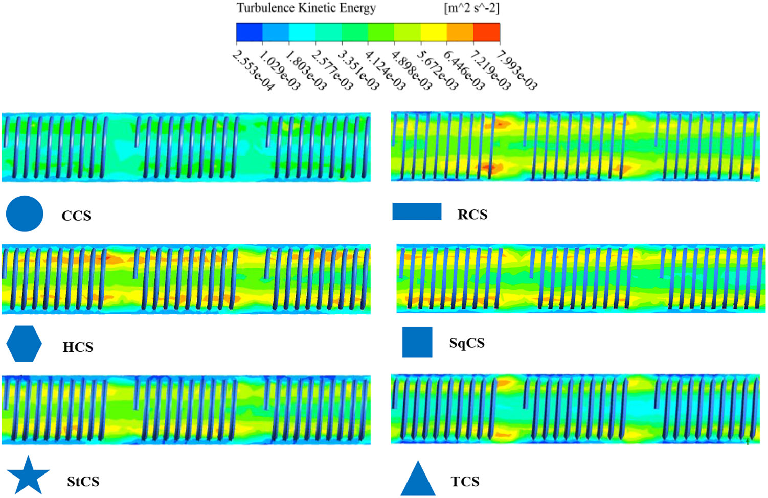
Figure 19: Turbulence kinetic energy contour for tube with wire coil at different cross section shape

Figure 20: Velocity contour for tube with wire coil at different cross section shape

Figure 21: Velocity vector for tube with wire coil at different cross section shape
From the figures, it can be seen that the wire coil with circular cross-section causes uniform distribution of flow velocity, which reduces flow resistance and pressure loss. Thanks to the homogeneous and smooth flow across the surfaces of the wire coil, the heat exchange efficiency increases. A wire coil with a rectangular cross-section can affect how heat is distributed, causing heat to concentrate in certain places and disperse in others. On the other hand, this cross-section shape enhances heat transfer by increasing the surface area of the wire.
Due to the multifacetedness of the wire coil with a hexagonal cross-section, the flow resistance increases and the fluid velocity distribution inside the pipe changes. Which causes the thermal and hydraulic performance inside the pipe to be clearly affected. Heat exchange is improved when the wire coil has a square cross-section. The edges and spatial overlaps of the wire coils improve heat exchange due to smooth flow and uniform velocity distribution which reduces pressure loss.
Thermal and hydraulic performance is affected when wire coils with a triangular cross section are inserted into the tube. It can be notice that the heat exchange between the liquid, the wire coil, and the tube walls is affected due to the change in the flow path of the liquid as a result of the sharp angles possessed by the wire coil with a triangular cross section. It is obvious that a clear improvement in heat transfer when using wire coils with a star-shaped cross-section. The star shape increases the active surface area available for heat exchange, allowing for higher heat exchange efficiency. On the other hand, due to the complex geometry of the shape and having multiple surfaces and edges, the flow resistance and interference increase, resulting in increased pressure loss and uneven velocity distribution.
It is important to consider the balance between enhanced heat transfer and associated pressure reduction when designing. The cross-sectional shape of the coiled wire can be designed to direct and distribute the fluid flow in specific ways within the pipe. This can result in better channeling of thermal currents and better distribution of heat through the tube. Therefore, the heat transfer efficiency can be improved and distributed more effectively.
• The average PEC enhancement ratio compared with a plain tube without wire coil reached about 9.1% for a TWD, 5.5% for an SWD, and 4.6% for an FWD. The wire coils, according to the arrangement (TWD), gave the best PEC.
• The addition of a wire coil enhances the values of Nu and increases f compared to a plain tube. 62%, 72%, 66%, 64%, 79%, and 57%, respectively, is the average increase ratio for Nu in wire coils featuring circular, rectangular, hexa, square, star, and triangle cross sections. The wire coils featuring circular, rectangular, hexa, square, star, and triangle cross sections exhibit average increase ratios for f of 352%, 473%, 372%, 405%, 431%, and 316%, respectively.
• The enhancement of heat transfer capability of various cross-sections is as follows: StCS > RCS > HCS > SqCS > CCS > TCS.
• The pump consumption of various cross-sections is as follows: RCS > StCS > SqCS > HCS > CCS > TCS.
Acknowledgement: Author would like to thank Mustansiriyah University (https://uomustansiriyah.edu.iq/) Baghdad, Iraq for its support in present study.
Funding Statement: The author received no specific funding for this study.
Author Contributions: The author A. S. G confirms contribution to the paper as follows: study conception, design, data collection, analysis, interpretation of results and draft manuscript.
Availability of Data and Materials: The data are available when requested.
Conflicts of Interest: The author declares that they have no conflicts of interest to report regarding the present study.
References
1. Kongkaitpaiboon, V., Nanan, K., Eiamsa-ard, S. (2010). Experimental investigation of convective heat transfer and pressure loss in a round tube fitted with circular ring tabulators. International Communications in Heat and Mass Transfer, 37, 568–574. https://doi.org/10.1016/j.icheatmasstransfer.2009.12.016 [Google Scholar] [CrossRef]
2. Eiamsa-ard, S., Wongcharee, K., Eiamsa-ard, P., Thianpong, C. (2010). Heat transfer enhancement in a tube using delta-winglet twisted tape inserts. Applied Thermal Engineering, 30(4), 310–318. https://doi.org/10.1016/j.applthermaleng.2009.09.006 [Google Scholar] [CrossRef]
3. Srivastava, G. P., Patil, A. K., Kumar, M. (2021). Parametric effect of diverging perforated cones on the thermo-hydraulic performance of a heat exchanger pipe. Heat and Mass Transfer, 57, 1425–1437. https://doi.org/10.1007/s00231-021-03035-8 [Google Scholar] [CrossRef]
4. Hosseinnejad, R. H., Farhadi, M. M. (2019). Turbulent heat transfer in tubular heat exchangers with twisted tape. Journal of Thermal Analysis and Calorimetry, 135(3), 1863–1869. https://doi.org/10.1007/s10973-018-7400 [Google Scholar] [CrossRef]
5. Wijayanta, A. T., Mirmanto, Muhammad, A. (2019). Heat transfer augmentation of internal flow using twisted tape insert in turbulent flow. Heat Transfer Engineering, 41(14), 1288–1300. https://doi.org/10.1016/j.est.2021.103009 [Google Scholar] [CrossRef]
6. Vignesh, S., Moorthy, V. S., Nallakumarasamy, G. (2017). Experimental and CFD analysis of concentric dimple tube heat exchanger. International Journal of Emerging Technologies in Engineering Research (IJETER), 5(7), 18–26. [Google Scholar]
7. Jafari, M., Daribi, S., Farhadi, M., Sedighi, K. (2017). Effects of a three-lobe swirl generator on the thermal and flow fields in a heat exchanging tube: An experimental and numerical approach. International Journal of Energy Conversion and Management, 148, 1358–1371. https://doi.org/10.1016/j.enconman.2017.06.074 [Google Scholar] [CrossRef]
8. Singh, S. K. R., Sarkar, J. (2020). Improving hydrothermal performance of hybrid nanofluid in double tube heat exchanger using tapered wire coil turbulator. Advanced Powder Technology, 31(5), 2092–2100. https://doi.org/10.1016/j.apt.2020.03.002 [Google Scholar] [CrossRef]
9. Zhang, X., Liu, Z., Liu, W. (2013). Numerical studies on heat transfer and friction factor characteristics of a tube fitted with helical screw-tape without core-rod inserts. International Journal of Heat and Mass Transfer, 60, 490–498. https://doi.org/10.1016/j.ijheatmasstransfer.2013.01.041 [Google Scholar] [CrossRef]
10. Wang, Y., Alvarado, J. L., Terrell, W. (2018). Thermal and flow characteristics of helical coils with reversed loops. International Journal of Heat and Mass Transfer, 126, 670–680. https://doi.org/10.1016/j.ijheatmasstransfer.2018.02.110 [Google Scholar] [CrossRef]
11. Gholamalizadeh, E., Hosseini, E., Jamnani, M. B., Amiri, A., Saee, A. D. et al. (2019). Study of intensification of the heat transfer in helically coiled tube heat exchangers via coiled wire inserts. International Journal of Thermal Sciences, 141, 72–83. https://doi.org/10.1016/j.ijthermalsci.2019.03.029 [Google Scholar] [CrossRef]
12. Bhuiya, M. M. K., Chowdhury, M. S. U., Ahamed, J. U., Khan, M. J. H., Sarkar, M. A. R. et al. (2012). Heat transfer performance for turbulent flow through a tube using double helical tape inserts. International Communications in Heat and Mass Transfer, 39, 818–825. [Google Scholar]
13. Guo, J., Fan, A. W., Zhang, X. Y., Liu, W. (2011). A numerical study on heat transfer and friction factor characteristics of laminar flow in a circular tube fitted with center-cleared twisted tape. International Journal of Thermal Sciences, 50, 263–1270. https://doi.org/10.1016/j.ijthermalsci.2011.02.010 [Google Scholar] [CrossRef]
14. Eiamsa-ard, S., Wongcharee, K., Sripattanapipat, S. (2009). 3-D Numerical simulation of swirling flow and convective heat transfer in a circular tube induced by means of loose-fit twisted tapes. International Communications in Heat and Mass Transfer, 36(9), 947–955. https://doi.org/10.1016/j.egypro.2014.03.040 [Google Scholar] [CrossRef]
15. Ibrahim, S. H., Naji, Z. H. (2023). Augmentation heat transfer in a circular pipe using twisted-tape inserts: A review. Journal of Engineering and Sustainable Development, 27(4), 511–526. https://doi.org/10.31272/jeasd.27.4.8 [Google Scholar] [CrossRef]
16. Chang, S. W., Huang, B. J. (2014). Thermal performances of tubular flows enhanced by ribbed spiky twist tapes with and without edge notches. International Journal of Heat and Mass Transfer, 73, 645–663. https://doi.org/10.1016/j.ijheatmasstransfer.2014.02.049 [Google Scholar] [CrossRef]
17. Skullong, S., Promvonge, P., Thianpong, C., Pimsarn, M. (2016). Heat transfer and turbulent flow friction in a round tube with staggered-winglet perforated-tapes. International Journal of Heat and Mass Transfer, 95, 230–242. https://doi.org/10.1016/j.ijheatmasstransfer.2015.12.007 [Google Scholar] [CrossRef]
18. Thianpong, C., Eiamsa-ard, P., Promvonge, P., Eiamsa-ard, S. (2012). Effect of perforated twisted-tapes with parallel wings on heat transfer enhancement in a heat exchanger tube. Energy Procedia, 14, 1117–1123. https://doi.org/10.1016/j.egypro.2011.12.1064 [Google Scholar] [CrossRef]
19. Saha, S., Saha, S. K. (2013). Enhancement of heat transfer of laminar flow of viscous oil through a circular tube having integral helical rib roughness and fitted with helical screw-tapes. Experimental Thermal and Fluid Science, 47, 81–89. [Google Scholar]
20. Fan, F., Pan, Y., Qi, C., Liu, M., Yan, Y. (2020). Effects of turbulator with round hole on the thermo-hydraulic performance of nanofluids in a triangle tube. International Journal of Heat and Mass Transfer, 146, 118897. https://doi.org/10.1016/j.ijheatmasstransfer.2019.118897 [Google Scholar] [CrossRef]
21. Shelare, S. D., Aglawe, K. R., Belkhode, P. N., (2022). A review on twisted tape insertsfor enhancing the heat transfer. Materials Today: Proceedings, 54(3), 560–565. https://doi.org/10.1016/j.matpr.2021.09.012 [Google Scholar] [CrossRef]
22. Singh S. K., Sarkar, J. (2021). Hydrothermal performance comparison of modifiedtwisted tapes and wire coils in tubular heat exchanger using hybrid nanofluid. International Journal ofThermal Sciences, 166, 106990. https://doi.org/10.1016/j.ijthermalsci.2021.106990 [Google Scholar] [CrossRef]
23. Xiong, Q. A., Izadi, M., Shokri-Rad, M., Shehzad, S. A., Mohammed, H. A. (2021). 3D Numerical study of conical and fusiform turbulators for heat transfer improvement in a double-tube heat exchanger. International Journal of Heat and Mass Transfer, 170, 120995. https://doi.org/10.1016/j.ijheatmasstransfer.2021.120995 [Google Scholar] [CrossRef]
24. Qasim, M. S., Ali, S. G., Freegah, B. (2021). Conical wire coil inserts effect on the thermo-hydraulic characteristics in circular copper tube. IOP Conf. Series: Materials Science and Engineering, vol. 1182, pp. 012065. Eforie Nord, Romania. https://doi.org/10.1088/1757-899X/1182/1/012065 [Google Scholar] [CrossRef]
25. Ahmad, M., Anuradha, P., Gupta, G. (2019). CFD analysis of heat transfer enhancement using wire coil turbulator as insert in corrugated tube heat exchanger. The IUP Journal of Mechanical Engineering, XII(4), 49–65. https://ssrn.com/abstract=3796648 [Google Scholar]
26. Chompookham, T., Chingtuaythong, W., Chokphoemphun, S. (2022). Influence of a novel serrated wire coil insert on thermal characteristics and air flow behavior in a tubular heat exchanger. International Journal of Thermal Sciences, 171, 107184. https://doi.org/10.1016/j.ijthermalsci.2021.107184 [Google Scholar] [CrossRef]
27. Du, J., Hong, Y., Wang, S., Ye, W. B., Huang, S. M. (2018). Experimental thermal and flow characteristics in a traverse corrugated tube fitted with regularly spaced modified wire coils. International Journal of Thermal Sciences, 133, 330–340. https://doi.org/10.1016/j.ijthermalsci.2018.05.032 [Google Scholar] [CrossRef]
28. Hamad, L. B. (2017). Parametric study of heat transfer and pressure drop characteristics in a tube using different types of inserts (Thesis). Institute of Science and Technology Mechanical and Aeronautical Engineering Department. https://acikbilim.yok.gov.tr/handle/20.500.12812/131863 (accessed on 25/11/2023). [Google Scholar]
29. Rouse, H. (1946). Elementary mechanics of fluids, 1st edition. John Wiley & Sons, Inc. https://gidropraktikum.narod.ru/Rouse-Elementary-Mechanics-of-Fluids.pdf. [Google Scholar]
30. Yu, C., Zhang, H., Wang, Y., Zeng, M., Gao, B. (2020). Numerical study on turbulent heat transfer performance of twisted oval tube with different cross sectioned wire coil. Case Studies in Thermal Engineering, 22, 100759. https://doi.org/10.1016/j.csite.2020.100759 [Google Scholar] [CrossRef]
Cite This Article
 Copyright © 2024 The Author(s). Published by Tech Science Press.
This work is licensed under a Creative Commons Attribution 4.0 International License , which permits unrestricted use, distribution, and reproduction in any medium, provided the original work is properly cited.
 Downloads
 Citation Tools