
 Submit a Paper
 Propose a Special lssue
 Open Access
ARTICLE
Investigate the Impact of Dimple Size and Distribution on the Hydrothermal Performance of Dimpled Heat Exchanger Tubes
Mechanical Engineering Department, College of Engineering, Mustansiriyah University, Baghdad, Iraq
* Corresponding Author: Abeer H. Falih. Email:
(This article belongs to the Special Issue: Passive Heat Transfer Enhancement for Single Phase and Multi-Phase Flows)
Frontiers in Heat and Mass Transfer 2024, 22(2), 597-613. https://doi.org/10.32604/fhmt.2024.049812
Received 18 January 2024; Accepted 20 February 2024; Issue published 20 May 2024
 View Full Text
 Download PDF
Abstract
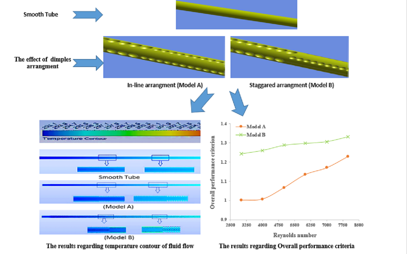
In this study, the primary objective was to enhance the hydrothermal performance of a dimpled tube by addressing areas with low heat transfer compared to other regions. To accomplish this, a comprehensive numerical investigation was conducted using ANSYS Fluent 2022 R1 software, focusing on different diameters of dimples along the pipe’s length and the distribution of dimples in both in-line and staggered arrangements. The simulations utilized the finite element method to address turbulent flow within the tube by solving partial differential equations, encompassing Re numbers spanning from 3000 to 8000. The study specifically examined single-phase flow conditions, with water utilized as the cooling fluid. The results of the investigation indicated that increasing the Reynolds number resulted in higher average Nusselt numbers, pressure drops, the overall performance criterion, and a reduction in average thermal resistance across all models analyzed. Notably, both proposed models demonstrated improved heat transfer when compared to the conventional model. Out of all the models evaluated, the tube featuring staggered dimples (Model B) demonstrated the most notable improvement in the Nu number. It exhibited an enhancement of approximately twice the value compared to the conventional model. The mean thermal resistance for the tube with dimples in the staggered arrangement (Model B) is 0.0057 k/W, compared to 0.0118 k/W for the traditional model. The maximum overall performance criterion for Model -A- and Model -B- is 1.22 and 1.33, respectively.Graphic Abstract
Keywords
Nomenclature
| Symbol | Definition Unit |
| A_(s,t) | The tube surface area mm2 |
| Cpw | Specific heat at constant pressure KJ/Kg.K |
| D | Diameter of tube mm |
| haw | Average heat transfer coefficient of water W/m2.k |
| Kw | Thermal conductivity of water W/m.K |
| m | Mass flow rate Kg/s |
| (Nu) ̅ | Nusselt number |
| (Nu) ̅_tst | The average Nu number of the traditional smooth tube |
| L | The tube length m |
| f | Fraction factor |
| f_tst | Friction factor of the traditional smooth tube |
| OPC | The overall performance criterion |
| P | Pressure Pa |
| q | The heat flux W/m2 |
| Q | Rate of Heat flow W |
| Tin,w | The inlet temperature of water K |
| Tout,w | The outlet temperature of water K |
| Tm,t | The mean temperature of the tube wall K |
| T_(m,w) | The mean bulk temperature of water K |
| V_w | The mean velocity of water m/s |
| ρ_w | Density of water kg/m3 |
| Δp | Pressure drop N/m2 |
Heat exchangers are devices widely used in many industrial and engineering applications around the world. So, it has become necessary to improve the hydrothermal performance and efficiency of such devices to reduce their size, reduce their cost, and make them more suitable for many different applications. Generally, there are two main techniques to improve heat transfer: passive and active techniques. The current study will focus on the passive technique because it does not require external devices and is thus less costly as compared to the active technique. Increasing the surface roughness of pipe is one of the better passive techniques that can be achieved by using different configurations like ribs, dimples, and corrugation. All these configurations are meant to increase flow mixing, enhance turbulent flow, and redevelop the boundary layer, thus improving the rate of heat transfer [1,2]. When rough surface techniques are used instead of smooth walls, it significantly increases the rate of heat transfer and pressure losses [3–6]. Numerous earlier investigations have shown that, when compared to the conventional smooth tube, heat exchangers of the corrugated tube type stand out for their comparatively good thermal response. This type does, however, have an unfavorable pressure drop and needs a powerful pump. Recently, many researchers have studied the effect of various geometric parameters of dimples, such as dimple shapes [7–9], distance between dimples [10–12], diameter of the dimple [13–15], and angle [16,17], on the hydrothermal response. Farsad et al. [18] conducted a comparison between the heat transfer at the interface of a Dimpled-Protruded tube and a smooth tube. The results revealed that small vorticities led to an improvement in interfacial heat transfer, and rough tubes exhibited an important enhancement of 36.21% in heat transfer along with an increase in friction losses. The effects of dimple depth, number, and arrangement on flow and heat transfer characteristics under turbulent flow were studied by Nazari et al. [19]. They claimed that the mean Nusselt number was higher for the dimpled surface than it was for the smooth plate. The disadvantage of this technique is that there will be more pressure loss because of the increased friction drag and recirculation zones inside the dimples. Vignesh et al. [20] conducted a numerical and experimental study to investigate the effect of using dimpled tubes on the hydrothermal performance of a double-pipe heat exchanger. They reported that using the dimpled tube improved heat transfer noticeably as compared to using the smooth tube. Xie et al. [21,22] conducted a numerical study to examine the effect of dimples and protrusion depth on the thermal performance of dimpled tubes numerically. The results have shown that using dimpled tubes leads to improved heat transfer compared to smooth tubes. The effect of the plain and spherical dimples on the hydrothermal response of the dimpled tube was studied by Xie et al. [23]. The results have shown that both shapes of dimples illustrated significant improvement in the hydrothermal response of such tubes. Xie et al. [24] performed a numerical study to examine the effect of cross-ellipsoidal dimples on heat transfer. They reported that using the longitudinal and transverse dimples considerably enhanced heat transfer. The influence of the dimple depth and pitch on the thermal response of a dimpled tube has been studied by Zhang et al. [25]. They reported that an increase in dimple depth leads to an increase in Nu/Nuo and f/fo, while an increased pitch leads to a decrease in Nu/Nuo and f/fo. Among the cases considered, the ETSD with a dimple depth (D) of 1.5 mm, pitch (P) of 30 mm, axis ratio (R) of 2.33, and Reynolds number (Re) of 5000 exhibits the highest PEC (Performance Evaluation Criteria) value of approximately 2.02.
Despite the huge number of research studies that tried to enhance the thermal response of dimpled tubes, most of these studies did not take into account the regions where the heat transfer is less than in other areas. So, the objective of the current study is to address the issue of low heat transfer in these areas of dimpled tubes by focusing on those areas and implementing certain modifications. The researchers aimed to increase the surface area for heat transfer and enhance the randomness of the working fluid. This was achieved by increasing the diameter of dimples present on the surface of the dimpled tube. The dimpled tube consists of three primary regions, each with a distinct dimple diameter. The dimple diameters in the first, second, and third regions were 1, 2, and 3 mm, respectively. There were differences in the spacing between the dimple centers for each region; the first, second, and third regions used 3, 5, and 7 mm, respectively. Furthermore, for all three regions, a 90-degree angle was maintained between the dimples surrounding the pipe. Additionally, the study looked into two dimple arrangements: staggered and in-line. These configurations describe how the dimples are positioned in relation to one another. The dimples are offset from one another in a staggered arrangement, whereas they are aligned in a straight line in an in-line arrangement. The current study intends to improve the thermal performance of dimpled tubes by enhancing heat transfer in areas that previously exhibited low performance by examining these various dimple configurations and arrangements. This current study focused on double pipe heat exchanger type. The water is used inside the tube while outside the tube (annular tube), instead of the working fluid (water), the constant heat flux is used in order to simplify the case study.
The present study is focused on carrying out a numerical analysis of hydrothermal improvement in a 3-D circular tube with different sizes and arrangements of dimples. The main objective of this study is to investigate the flow behavior within the dimpled tube and improve its hydrothermal performance. Fig. 1 provides an overview of the various geometries considered in the analysis. The material chosen for the pipe is copper, and its key dimensions are as follows: an inner diameter of 17.272 mm, an outer diameter of 18.161 mm, and a length of 1000 mm. The first model, called the smooth model, is without any dimples, as shown in Fig. 1a. The second model is Model -A- which consists of three areas with different specifications: in the first area, the dimple radius is 1 mm, and the distance between the centers of the dimples is 3 mm, the second area, the dimple radius is 2 mm, and the distance between the centers of the dimples is 5 mm, in the third area, the dimple radius is 3 mm, and the distance between the centers of the dimples is 7 mm with an in-line arrangement as shown in Fig. 1b. While the third model is Model -B- is similar to Model -A- but with a staggered arrangement as shown in Fig. 1c. For both proposals models (A and B), the angle between any two dimples around the circumvent of the tube is 90°.
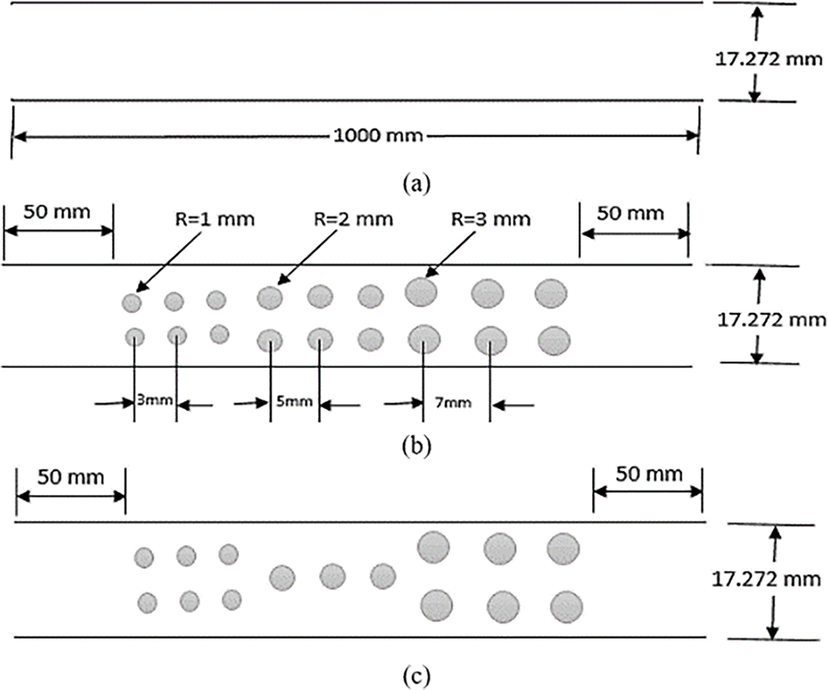
Figure 1: The physical model with different dimple configurations
2.2 The Mesh Domain of the Traditional and Proposal Models
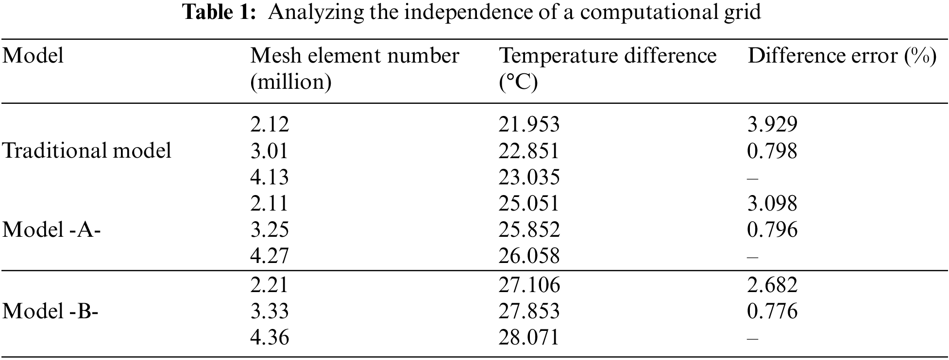
In the current work, the grid employed for the numerical calculations consists of tetrahedral elements in both the wall and flow domains. This grid is generated with an increased density near the wall to effectively capture the abrupt temperature and velocity gradients, as shown in Fig. 2. This figure shows that the flow mesh domain for a smooth tube is relatively simple, consisting of regular and well-defined layers, while the flow mesh domain of a dimpled tube is more intricate. The mesh domain in a dimpled tube varies depending on factors such as the size, shape, and distribution of the dimples. Moreover, mesh independence tests were conducted to increase the reliability of the computational results. Temperature is a very important parameter to predict the thermal response of the heat exchanger, so the temperature differential across the tube was selected as the primary measure to evaluate the results of mesh independence. Based on the results presented in Table 1, the temperature differentials for the grids with around three million elements showed a difference of less than 0.8%. This indicates that the numerical calculations were relatively insensitive to further grid refinement beyond three million elements. Therefore, the grid with around three million elements, which provided accurate results while maintaining computational efficiency, was selected for carrying out additional analysis using numerical simulation calculations.
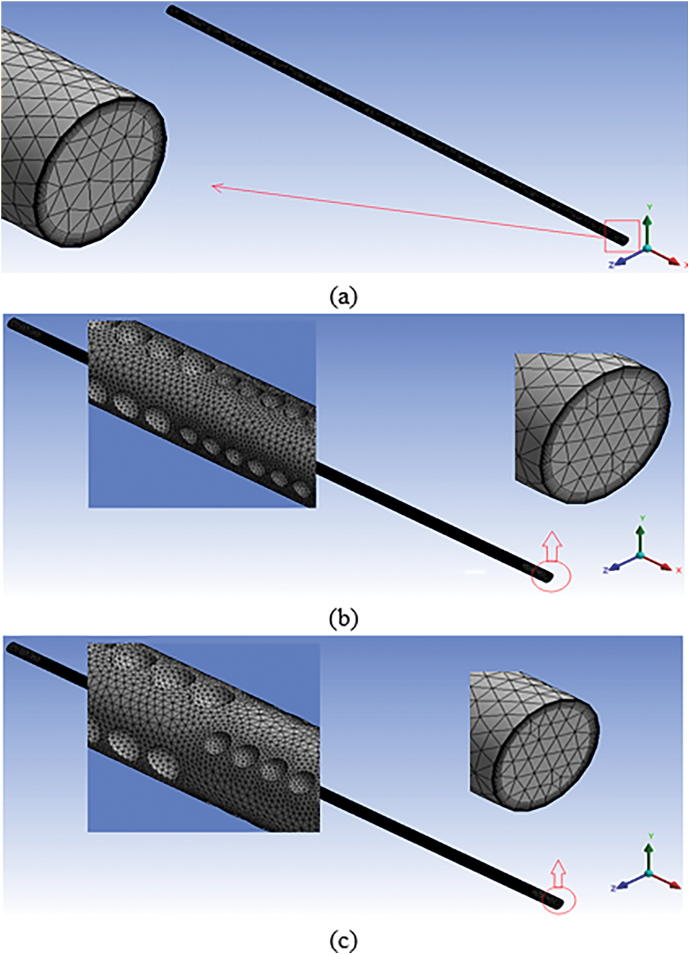
Figure 2: Flow mesh domain for (a) traditional model, (b) dimpled tube with in-line arrangement and (c) dimpled tube with staggered arrangement
2.3 Boundary Conditions and Governing Equations
In the current analysis, turbulent flow within a pipe of a heat exchanger was investigated. The Reynolds number (Re) range under study was 3000–8000, indicating a flow regime characterized by turbulence. Water was chosen as the working fluid for the simulations. To simplify the analysis, the physical properties of water are assumed to remain constant throughout the study. This assumption was reasonable because the operational temperature range within the heat exchanger was small, specifically at a temperature of 300 K. The water temperature at the inlet is 300 K, and the water flow rate is uniform, with the flow rates corresponding to Reynolds numbers of (3000, 4000, 5000, 6000, 7000, and 8000). The zero-pressure outlet boundary condition was employed in the simulations. This condition implies that the pressure at the outlet of the pipe was assumed to be atmospheric pressure. Additionally, a constant heat flux of 10,000 W/m² was applied to the outer surface of the dimpled tube, as depicted in Fig. 3. This means that a fixed amount of heat was transferred per unit area on the outer surface of the tube. It is worth noting that all the boundary conditions used in this study were identical to those employed in a previous experimental study [26].
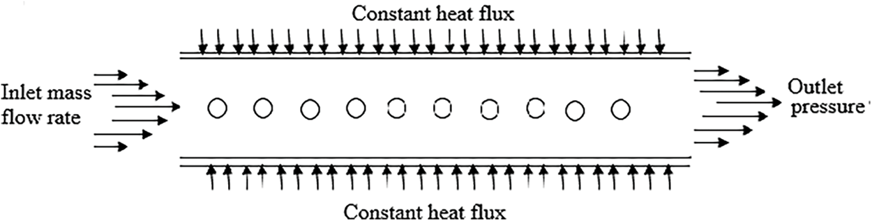
Figure 3: Boundary conditions
The working fluid employed was water, which possessed the following properties: an initial density of 998.2 kg/m³, a specific heat of 4.182 kJ/kg·°C, a dynamic viscosity of 1.003 × 10−³ kg/m·s, a thermal conductivity of 0.6 W/m·°C, and a thermal expansion rate of 0.000149 K−¹ [27]. The pipes were constructed using copper material, which had a density of 8978 kg/m³, a specific heat of 381 kJ/kg·°C, and a thermal conductivity of 387.6 W/m·°C. All models considered in the study were subjected to an operating pressure of 101.3 kPa and a gravitational acceleration of 9.81 m/s².
The equations of continuity, momentum, and heat transport were solved using steady Reynolds Averaged Navier-Stokes (RANS) [28], and under several simplifications and assumptions, the following can be stated:
1. The flow is assumed to be steady, turbulent, and incompressible.
2. The properties of the water and the pipe material are considered to be independent of temperature and are assumed to remain constant.
3. The contribution of radiation heat transfer is believed to be negligible and can be disregarded.
4. The effect of gravity is considered to be negligible and is not taken into account.
5. The surface of the pipe wall is assumed to be smooth, and a constant heat flux is applied to it.
6. The effects of vibration are not considered in this analysis.
Based on the preceding assumptions, we can express the governing equations for fluid flow and thermal convection through the following partial differential equations:
• Continuity equation:
• Momentum equation:
• Energy equation:
The Realizable k-turbulence model with improved wall treatment was employed in this study to simulate the turbulence. Based on the current model, the equations of the modelled transport for both K and ε are given below [29]:
where
The default values of the model constant were defined (
The amount of heat transferred to water from the wall of the tube can be calculated as follows:
where
To estimate the average heat transfer coefficient, Newton’s law of cooling can be used [29,30].
where
The mean bulk temperature of water is calculated as follows [31]:
To calculate the average Nu number, Eq. (9) can be used.
where D represents the inner diameter of the tube, while
One of the most significant parameters that is used to estimate the hydraulic performance of the dimpled tube is the friction factor, which can be calculated from Eq. (10) [32–34].
where ΔP, ρw, Vm, and L represent the pressure drop across the tube, water density, the mean velocity of water, and tube length, respectively.
Usually, the overall performance criteria are used to assess the overall hydro-thermal response of the new proposal models according to the Nu number and friction factor as follows [35], where the extent of improvement can be evaluated as far as the OPC is greater than one.
where
Overall Performance Criteria (OPC) is a metric used to measure hydrothermal performance improvements compared to the conventional model. It represents the correlation between heat transfer and pressure drop, with a value greater than one indicating a positive change in the heat transfer process as compared to pressure drop.
To demonstrate the validity of the numerical results, this section compares the present results of the (CFD) with the experimental findings from earlier investigations. Both the geometry and the boundary conditions are used exactly in line with the experimental investigation conducted in Reference [11] in order to demonstrate the accuracy of the numerical results. This foundation was used to compare the Nusselt number and friction factor of the fluid flow inside the pipe at various Reynolds numbers, as shown in Fig. 4. The maximum deviation between the numerical results and experimental data for the Nusselt number is found to be 8.5%. In contrast, the maximum deviation between the empirical correlation equation [36], and the experimental data is 10.3%, as shown in Fig. 4a. Regarding the friction factor, the maximum deviation between the numerical results and experimental data is 10.8%, whereas the maximum deviation between the empirical correlation equation [37] and the experimental data is 11.2%, as illustrated in Fig. 4b. Experimental measurements often contain errors, and systems can undergo thermal losses, leading to differences between current results and those of reference [11]. Measurement errors can result from a variety of sources, such as instrument malfunctions, unfavorable environmental circumstances, or human error during data collection. All these mistakes affect the precision and accuracy of the measurements and introduce uncertainty. Whereas the accuracy of references [36,37] correlation may be the cause of the discrepancy between the current results and those calculated from it. Thus, it can be said that the established numerical approach is sufficiently accurate and may be used to analyze the effect of parameters taken into account in the present work, as described in the next section.
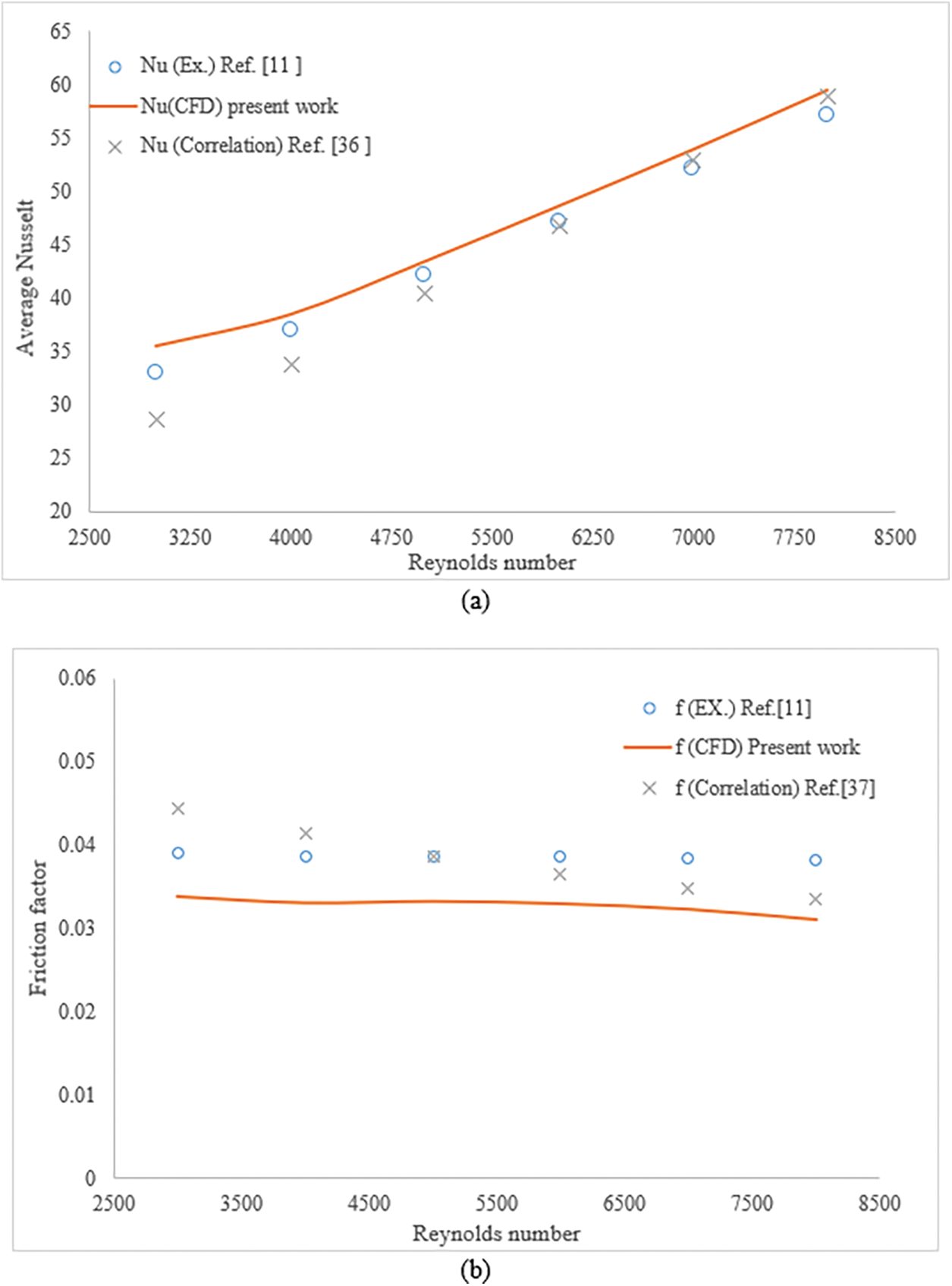
Figure 4: Validation of the numerical results of the conventional model under various Reynolds number for (a) Nusselt number and (b) friction factor
Fig. 5 illustrates the temperature distribution of the fluid flow in three different models: (a) the traditional model, (b) a dimpled tube with an in-line arrangement, and (c) a dimpled tube with a staggered arrangement. The fluid entering the system has an initial temperature of 293 K, a Reynolds number of 3000, and is subjected to a heat flux of 10 kW/m² in the x-y plane. The figure demonstrates that the temperature of the cooling fluid within the tube increases in the direction of the flow for all the models under investigation. The smooth tube, representing the traditional model (Fig. 5a), exhibits the lowest temperature for the cooling fluid. In contrast, the dimpled tube shows the highest cooling fluid temperature due to the presence of turbulence caused by the dimples within the tube, as depicted in Fig. 5b. Furthermore, Figs. 5b and 6c reveal that Model -B-, which employs a staggered arrangement of dimples, displays a higher cooling fluid temperature compared to Model -A-. This can be attributed to the enhanced thermal boundary layer development resulting from the dimple arrangement, particularly the staggered configuration. The development of the thermal boundary layer augments the surface area for heat transfer, consequently enhancing the efficiency of heat dissipation. The adoption of dimples in the proposed models, in addition to promoting thermal boundary layer development, also facilitates better mixing of the cooling fluid inside the tube. Consequently, this further contributes to improved heat transfer. Moreover, the highest temperatures reached by the cooling fluid in the traditional model, Model -A-, and Model -B- are 296, 299, and 301 K, respectively.
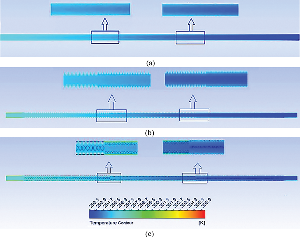
Figure 5: Temperature contour of fluid flow for (a) traditional model, (b) dimpled tube with in-line arrangement and (c) dimpled tube with staggered arrangement under study at Re = 3000
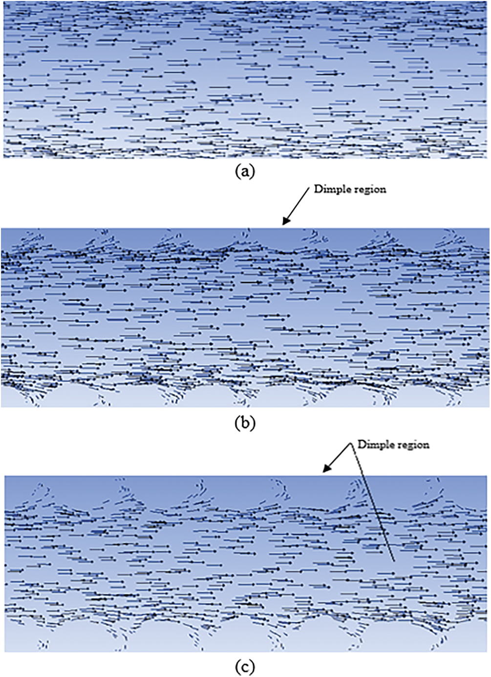
Figure 6: Velocity distribution of fluid flow for (a) traditional model, (b) dimpled tube with in-line arrangement and (c) dimpled tube with a staggered arrangement under study at Re = 3000
Fig. 6 depicts the distribution of fluid flow inside the tube for a Reynolds number of 3000 under a constant heat flux of 10 KW/m2. The main aim of this figure is to clarify the effect of dimples on fluid flow and demonstrate the consistent turbulent flow around the dimple. In a smooth tube, the inner surface is considered to be completely smooth and free of any irregularities or roughness, and hence the flow is relatively simple, consisting of regular and well-defined layers or streamlines, as shown in Fig. 6a. In contrast, a dimpled tube has intentional irregularities or indentations on its inner surface, which are known as dimples. These dimples can alter the flow characteristics of the flow and have been found effective in reducing thermal resistance and enhancing heat transfer, as shown in Figs. 6b and 6c.
The effect of the dimple arrangement under study on the average Nusselt number (Nu) for different Reynolds numbers under a constant heat flux of 10,000 W/m2 and an inlet temperature of 293 K is demonstrated in Fig. 7. As it is evident from this figure with an increase in the Reynolds number, the average Nu number increases for all cases under consideration. This can be attributed to the increased turbulence as a result of the increased velocity of the flow. This figure also suggests that both dimple arrangements enhance heat transfer significantly. The average Nu number for Model -A- and Model B is 38.7% and 46% higher, respectively, compared to the traditional model. Furthermore, the staggered arrangement of dimples (Model -B-) demonstrates superior heat transfer performance compared to the in-line arrangement (Model -A-). This indicates that more heat is transferred from the surface of the pipe to the cold fluid in Model -B-. It can be concluded that the staggered arrangement of dimples enhances turbulence more effectively compared to the in-line arrangement and hence leads to enhanced heat transfer.
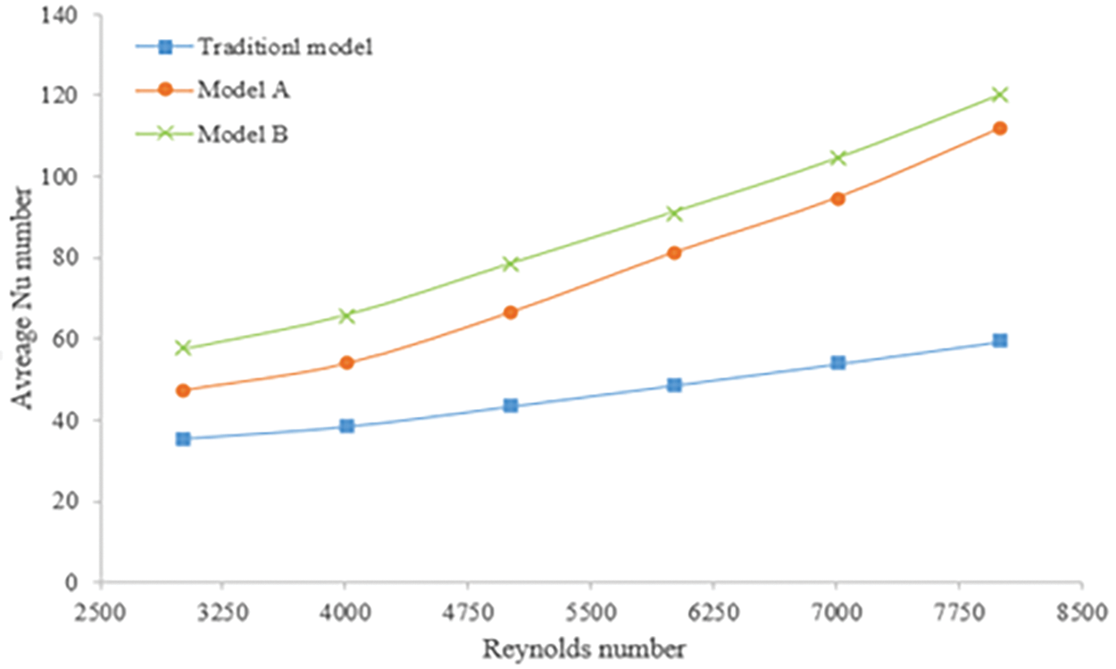
Figure 7: The influence of different dimple arrangements under study on the average Nu number at various Reynolds numbers
The effect of different configurations of the tubes under study (traditional tube and dimpled tube for both arrangements) on average thermal resistance for various Reynolds numbers under a constant heat flux of 10,000 W/m2 and an inlet temperature of 293 K is exhibited in Fig. 8. Noticeably, the average thermal resistance decreases as the flow rate increases. In comparison to the conventional model, the proposed models demonstrate a reduced level of average thermal resistance. Improved performance of such systems is associated with a decrease in the average thermal resistance. Utilizing dimples results in the breakdown of thermal layers, leading to a decrease in thermal resistance. When the Reynolds number reaches 8000, Model -B- achieves the lowest average thermal resistance of 0.00388, followed by Model -A- with 0.00417. In contrast, the traditional model without dimples exhibits the highest average thermal resistance of 0.00895. Model -B- demonstrates a significant 51% reduction in average thermal resistance compared to the traditional model, while Model -A- shows a reduction of 43%.

Figure 8: The influence of different dimple arrangements under study on the average thermal resistance under various Reynolds number
Fig. 9 shows the effect of different configurations of tube under study (traditional tube and dimpled tube for both arrangements) on the pressure drop for various Reynolds number of flow under a constant heat flux of 10 KW/m2 and the inlet temperature of water of 293 K. This figure reveals that the increase in pressure drop is associated with an increase in flow rate. The suggested tube configurations exhibited higher pressure drops compared to the traditional model. This phenomenon can be attributed to the interaction between the fluid and the dimples present along the tube. Moreover, the two proposed models demonstrated similar pressure drops due to an equal number of dimples. Furthermore, it was observed that Models -A- and -B- showed significant increases in pressure drop, with increments of 69.28% and 67.95%, respectively, compared to the traditional model.

Figure 9: The variation of the pressure drop for different dimple arrangements under study under various Reynolds number
The impact of different tube configurations under study on the friction factor at various Reynolds numbers under a constant heat flux of 10 KW/m2 and an inlet water temperature of 293 K is depicted in Fig. 10. This figure clearly indicates that, as the Reynolds number increases, the friction factor decreases. The proposed tube configurations exhibited higher friction factors compared to the traditional model. This can be attributed to the interaction between the fluid and the dimples present along the tube. Additionally, both proposed models demonstrated similar friction factors due to an equal number of dimples. Notably, Models -A- and -B- exhibited significant increases in friction factor, with average increments of 69.4% and 67.8%, respectively, compared to the traditional model.
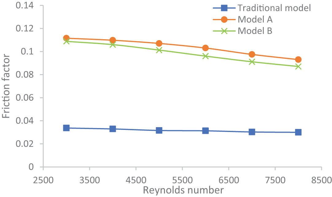
Figure 10: The variation of the friction factor of diverse dimple arrangements under study under different Reynolds numbers
Fig. 11 illustrates the performance characteristics of a dimpled tube with varying Reynolds numbers, subjected to a constant heat flux of 10 kW/m2, and an inlet temperature of 300 K. The arrangement of the dimples had a significant influence on the hydraulic and thermal performance of the tubes. Therefore, a thorough examination of the performance index was undertaken to determine the optimal choice among the innovative dimpled tubes. The performance index of the novel models showed an increasing trend. This observation can be attributed to the disturbance of the boundary layer by the dimples, which promotes turbulence near the pipe’s surface. Consequently, these configurations result in a substantial improvement in heat transfer but also lead to higher pressure drops compared to conventional tubes [38,39]. Furthermore, the overall performance criterion values for both configurations of the dimpled tube exceeded the threshold of 1, demonstrating the viability of all suggested models. Among the two models, Model -B- exhibited higher overall performance criteria than Model A. At higher Reynolds numbers, the overall performance criterion for Model A and Model B reached 1.22 and 1.33, respectively.
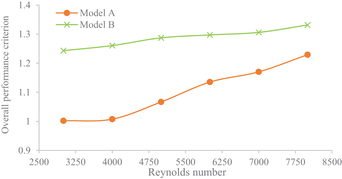
Figure 11: The performance criteria of different dimple arrangements under study under various Reynolds number
The present study investigates the impact of dimple arrangements on the fluid flow, heat transfer, thermal resistance, pressure drop, and overall performance characteristics of tubes. The numerical simulation model was validated by comparing it with previously published experimental results as well as the outcomes from some correlation equations. The comparison revealed a strong agreement, with a maximum deviation of 10%. This study yields numerous noteworthy conclusions.
1. The staggered arrangement of dimples (Model -B-) outperforms the in-line arrangement (Model -A-), transferring more heat from the pipe surface to the fluid. The average Nu number for Model -A- and Model -B- is 46% and 38.7% higher, respectively, compared to the traditional model. The reason behind that is the staggered arrangement of dimples that makes the flow more turbulent, hence increasing the heat transfer.
2. Model -B- demonstrates a superior average thermal resistance reduction of 51% compared to the traditional model, while Model -A- achieves a reduction of 43%. That is due to increased turbulent fluid flow as a result of the staggered arrangement of dimples and increased surface area.
3. Both Model -A- and Model -B- demonstrate significant increases in pressure drop compared to the traditional model, with increments of 69.28% and 67.95%, respectively.
4. The overall performance criterion values for both Model -A- and Model -B- exceed the threshold of (1), indicating the feasibility of all proposed models. Model -B- exhibits a higher overall performance criterion of 1.33 compared to Model -A-’s 1.22 at higher Reynolds numbers. That means that the improvement in heat transfer outweighs the downside of the increased pressure drop in the proposed models under the current study compared to smooth tubes.
In conclusion, the results of the current study provide valuable insights for the design and optimization of tube configurations for various applications that require efficient heat transfer and performance.
Acknowledgement: The authors would like to thank Mustansiriyah University in Baghdad, Iraq (www.uomustansiriyah.edu.iq) for its support of this study.
Funding Statement: The authors received no specific funding for this study.
Author Contributions: The authors confirm their contribution to the paper as follows: study conception and design: A.H.; data collection: B.S.; analysis and interpretation of results: A.H., B.F.; draft manuscript preparation: B.S. All authors reviewed the results and approved the final version of the manuscript.
Availability of Data and Materials: The data are available when requested.
Conflicts of Interest: The authors declare that they have no conflicts of interest to report regarding the present study.
References
1. Mangrulkar, Chidanand, K., Ashwinkumar, S. D., Sunil, C., Ashutosh, G. et al. (2019). Recent advancement in heat transfer and fluid flow characteristics in cross flow heat exchangers. Renewable and Sustainable Energy Reviews, 113, 109220. https://doi.org/10.1016/j.rser.2019.06.027 [Google Scholar] [CrossRef]
2. Mohammadi, S., Ajarostaghi, S. S. M., Pourfallah, M. (2020). The latent heat recovery from boiler exhaust flue gas using shell and corrugated tube heat exchanger: A numerical study. Heat Transfer, 49(6), 3797–3815. https://doi.org/10.1002/htj.v49.6 [Google Scholar] [CrossRef]
3. Mangrulkar, C. K., Dhoble, A. S., Abraham, J. D., Chamoli, S. (2020). Experimental and numerical investigations for effect of longitudinal splitter plate configuration for thermal-hydraulic performance of staggered tube bank. International Journal of Heat and Mass Transfer, 161, 120280. https://doi.org/10.1016/j.ijheatmasstransfer.2020.120280 [Google Scholar] [CrossRef]
4. Abraham, J. D., Dhoble, A. S., Mangrulkar, C. K. (2020). Numerical analysis for thermo-hydraulic performance of staggered cross flow tube bank with longitudinal tapered fins. International Communications in Heat and Mass Transfer, 118, 104905. https://doi.org/10.1016/j.icheatmasstransfer.2020.104905 [Google Scholar] [CrossRef]
5. Mohammed, A., Al-Gburi, H., Al-Abbas, A. (2023). Experimental study of the thermal performance of corrugated helically coiled tube-in-tube heat exchanger. Frontiers in Heat and Mass Transfer, 20, 1–7. https://doi.org/10.5098/hmt.20.17 [Google Scholar] [CrossRef]
6. Zhang, K., Li, Z., Yao, J. (2022). Numerical study on heat transfer characteristics of corrugated tube phase change thermal energy storage unit. Frontiers in Heat and Mass Transfer, 19, 1–8. https://doi.org/10.5098/hmt.19.5 [Google Scholar] [CrossRef]
7. Gürdal, M., Pazarlıoğlu, H. K., Tekir, M., Arslan, K., Gedik, E. (2022). Numerical investigation on turbulent flow and heat transfer characteristics of ferro-nanofluid flowing in dimpled tube under magnetic field effect. Applied Thermal Engineering, 200, 117655. https://doi.org/10.1016/j.applthermaleng.2021.117655 [Google Scholar] [CrossRef]
8. Zhang, L., Xiong, W., Zheng, J., Liang, Z., Xie, S. (2021). Numerical analysis of heat transfer enhancement and flow characteristics inside cross-combined ellipsoidal dimple tubes. Case Studies in Thermal Engineering, 25, 100937. https://doi.org/10.1016/j.csite.2021.100937 [Google Scholar] [CrossRef]
9. Dagdevir, T., Ozceyhan, V. (2021). An experimental study on heat transfer enhancement and flow characteristics of a tube with plain, perforated and dimpled twisted tape inserts. International Journal of Thermal Sciences, 159, 106564. https://doi.org/10.1016/j.ijthermalsci.2020.106564 [Google Scholar] [CrossRef]
10. Li, M., Khan, T. S., Hajri, E. A., Ayub, Z. H. (2016). Geometric optimization for thermal-hydraulic performance of dimpled enhanced tubes for single phase flow. Applied Thermal Engineering, 103, 639–650. https://doi.org/10.1016/j.applthermaleng.2016.04.141 [Google Scholar] [CrossRef]
11. Chen, J., Müller-Steinhagen, H., Duffy, G. G. B. (2001). Heat transfer enhancement in dimpled tubes. Applied Thermal Engineering, 21(5), 535–547. https://doi.org/10.1016/S1359-4311(00)00067-3 [Google Scholar] [CrossRef]
12. Shafaee, M., Mashouf, H., Sarmadian, A., Mohseni, S. G. (2016). Evaporation heat transfer and pressure drop characteristics of R-600a in horizontal smooth and helically dimpled tubes. Applied Thermal Engineering, 107, 28–36. https://doi.org/10.1016/j.applthermaleng.2016.06.148 [Google Scholar] [CrossRef]
13. Wang, Y., He, Y. L., Li, R., Lei, Y. G. (2009). Heat transfer and friction characteristics for turbulent flow of dimpled tubes. Chemical Engineering & Technology: Industrial Chemistry-Plant Equipment-Process Engineering-Biotechnology, 32(6), 956–963. https://doi.org/10.1002/ceat.v32:6 [Google Scholar] [CrossRef]
14. Wang, Y., He, Y. L., Lei, Y. G., Zhang, J. (2010). Heat transfer and hydrodynamics analysis of a novel dimpled tube. Experimental Thermal and Fluid Science, 34(8), 1273–1281. https://doi.org/10.1016/j.expthermflusci.2010.05.008 [Google Scholar] [CrossRef]
15. Cheraghi, M. H., Ameri, M., Shahabadi, M. (2020). Numerical study on the heat transfer enhancement and pressure drop inside deep dimpled tubes. International Journal of Heat and Mass Transfer, 147, 118845. https://doi.org/10.1016/j.ijheatmasstransfer.2019.118845 [Google Scholar] [CrossRef]
16. Lei, X. S., Shuang, J. J., Yang, P., Liu, Y. W. (2019). Parametric study and optimization of dimpled tubes based on response surface methodology and desirability approach. International Journal of Heat and Mass Transfer, 142, 118453. https://doi.org/10.1016/j.ijheatmasstransfer.2019.118453 [Google Scholar] [CrossRef]
17. Khan, M. Z. U., Akbar, B., Sajjad, R., Rajput, U. A., Mastoi, S. et al. (2021). Investigation of heat transfer in dimple-protrusion micro-channel heat sinks using copper oxide nano-additives. Case Studies in Thermal Engineering, 28, 101374. https://doi.org/10.1016/j.csite.2021.101374 [Google Scholar] [CrossRef]
18. Farsad, S., Mashayekhi, M., Zolfagharnasab, M. H., Lakhi, M., Farhani, F. et al. (2022). The effects of tube Dimples-Protrusions on the thermo-fluidic properties of turbulent forced-convection. Case Studies in Thermal Engineering, 35, 102033. https://doi.org/10.1016/j.csite.2022.102033 [Google Scholar] [CrossRef]
19. Nazari, S., Zamani, M., Moshizi, S. A. (2018). Comparative study on the influence of depth, number and arrangement of dimples on the flow and heat transfer characteristics at turbulent flow regimes. Heat and Mass Transfer, 54, 2743–2760. https://doi.org/10.1007/s00231-018-2307-5 [Google Scholar] [CrossRef]
20. Vignesh, S., Moorthy, V. S., Nallakumarasamy, G. (2017). Experimental and CFD analysis of concentric dimple tube heat exchanger. International Journal of Emerging Technology Engineering and Research (IJETER), 5(7), 18–26. [Google Scholar]
21. Xie, S., Liang, Z., Zhang, L., Wang, Y., Ding, H. (2019). Numerical investigation on flow and heat transfer in dimpled tube with teardrop dimples. International Journal of Heat and Mass Transfer, 131, 713–723. https://doi.org/10.1016/j.ijheatmasstransfer.2018.11.112 [Google Scholar] [CrossRef]
22. Vignesh, S., Moorthy, V. S., Nallakumarasamy, G. (2017). Experimental and CFD analysis of concentric dimple tube heat exchanger. International Journal of Emerging Technology Engineering Research (IJETER), 5(7), 18–26. [Google Scholar]
23. Xie, S., Liang, Z., Zhang, L., Wang, Y. (2018). A numerical study on heat transfer enhancement and flow structure in enhanced tube with cross ellipsoidal dimples. International Journal of Heat and Mass Transfer, 125, 434–444. https://doi.org/10.1016/j.ijheatmasstransfer.2018.04.106 [Google Scholar] [CrossRef]
24. Xie, S., Liang, Z., Zhang, L., Wang, Y., Ding, H. et al. (2018). Numerical investigation on heat transfer performance and flow characteristics in enhanced tube with dimples and protrusions. International Journal of Heat and Mass Transfer, 122, 602–613. https://doi.org/10.1016/j.ijheatmasstransfer.2018.01.106 [Google Scholar] [CrossRef]
25. Zhang, L., Xie, S., Liang, Z., Zhang, J., Wang, Y. et al. (2019). Numerical investigation of flow and heat transfer in enhanced tube with slot dimples. Heat and Mass Transfer, 55, 3697–3709. https://doi.org/10.1007/s00231-019-02685-z [Google Scholar] [CrossRef]
26. Li, M., Khan, T. S., Al-Hajri, E., Ayub, Z. H. (2016). Single phase heat transfer and pressure drop analysis of a dimpled enhanced tube. Applied Thermal Engineering, 101, 38–46. https://doi.org/10.1016/j.applthermaleng.2016.03.042 [Google Scholar] [CrossRef]
27. Mmhtl (1997). Fluid properties calculator. http://www.mhtl.uwaterloo.ca/old/onlinetools/airprop/airprop.html (accessed on 10/12/2023) [Google Scholar]
28. Wang, W., Zhang, Y., Li, Y., Han, H., Li, B. (2018). Numerical study on fully-developed turbulent flow and heat transfer in inward corrugated tubes with double-objective optimization. International Journal of Heat and Mass Transfer, 120, 782–792. https://doi.org/10.1016/j.ijheatmasstransfer.2017.12.079 [Google Scholar] [CrossRef]
29. Fluent, A. (2016). 17.0 ANSYS fluent meshing user’s guide. Canonsburg (PAANSYS Inc. [Google Scholar]
30. Kongkaitpaiboon, V., Promthaisong, P., Chuwattanakul, V., Wongcharee, K., Eiamsa-ard, S. (2019). Effects of spiral start number and depth ratio of corrugated tube on flow and heat transfer characteristics in turbulent flow region. Journal of Mechanical Science and Technology, 33, 4005–4012. https://doi.org/10.1007/s12206-019-0745-8 [Google Scholar] [CrossRef]
31. Wan, Y., Wu, R., Qi, C., Duan, G., Yang, R. (2018). Experimental study on thermo-hydraulic performances of nanofluids flowing through a corrugated tube filled with copper foam in heat exchange systems. Chinese Journal of Chemical Engineering, 26(12), 2431–2440. https://doi.org/10.1016/j.cjche.2018.07.007 [Google Scholar] [CrossRef]
32. Zhang, Y., Zhou, F., Kang, J. (2020). Flow and heat transfer in drag-reducing polymer solution flow through the corrugated tube and circular tube. Applied Thermal Engineering, 174, 115185. https://doi.org/10.1016/j.applthermaleng.2020.115185 [Google Scholar] [CrossRef]
33. Córcoles, J. I., Belmonte, J. F., Molina, A. E., Almendros-Ibáñez, J. A. (2019). Influence of corrugation shape on heat transfer performance in corrugated tubes using numerical simulations. International Journal of Thermal Sciences, 137, 262–275. https://doi.org/10.1016/j.ijthermalsci.2018.11.021 [Google Scholar] [CrossRef]
34. Qian, J. Y., Yang, C., Chen, M. R., Jin, Z. J. (2020). Thermohydraulic performance evaluation of multi-start spirally corrugated tubes. International Journal of Heat and Mass Transfer, 156, 119876. https://doi.org/10.1016/j.ijheatmasstransfer.2020.119876 [Google Scholar] [CrossRef]
35. Mei, S., Qi, C., Luo, T., Zhai, X., Yan, Y. (2019). Effects of magnetic field on thermo-hydraulic performance of Fe3O4-water nanofluids in a corrugated tube. International Journal of Heat and Mass Transfer, 128, 24–45. https://doi.org/10.1016/j.ijheatmasstransfer.2018.08.071 [Google Scholar] [CrossRef]
36. Gnielinski, V. (1976). New equations for heat and mass transfer in turbulent pipe and channel flow. International Chemical Engineering, 16(2), 359–367. [Google Scholar]
37. Petukhov, B. S. (1970). Heat transfer and friction in turbulent pipe flow with variable physical properties. Advances in Heat Transfer, 6, 504–564. [Google Scholar]
38. Rainieri, S., Bozzoli, F., Pagliarini, G. (2012). Experimental investigation on the convective heat transfer in straight and coiled corrugated tubes for highly viscous fluids: Preliminary results. International Journal of Heat and Mass Transfer, 55, 498–504. https://doi.org/10.1016/j.ijheatmasstransfer.2011.08.030 [Google Scholar] [CrossRef]
39. Aroonrat, K., Wongwises, S. (2011). Evaporation heat transfer and friction characteristics of R-134a flowing downward in a vertical corrugated tube. Experimental Thermal and Fluid Science, 35(1), 20–28. https://doi.org/10.1016/j.expthermflusci.2010.08.002 [Google Scholar] [CrossRef]
Cite This Article
 Copyright © 2024 The Author(s). Published by Tech Science Press.
This work is licensed under a Creative Commons Attribution 4.0 International License , which permits unrestricted use, distribution, and reproduction in any medium, provided the original work is properly cited.
 Downloads
 Citation Tools